

На этой странице
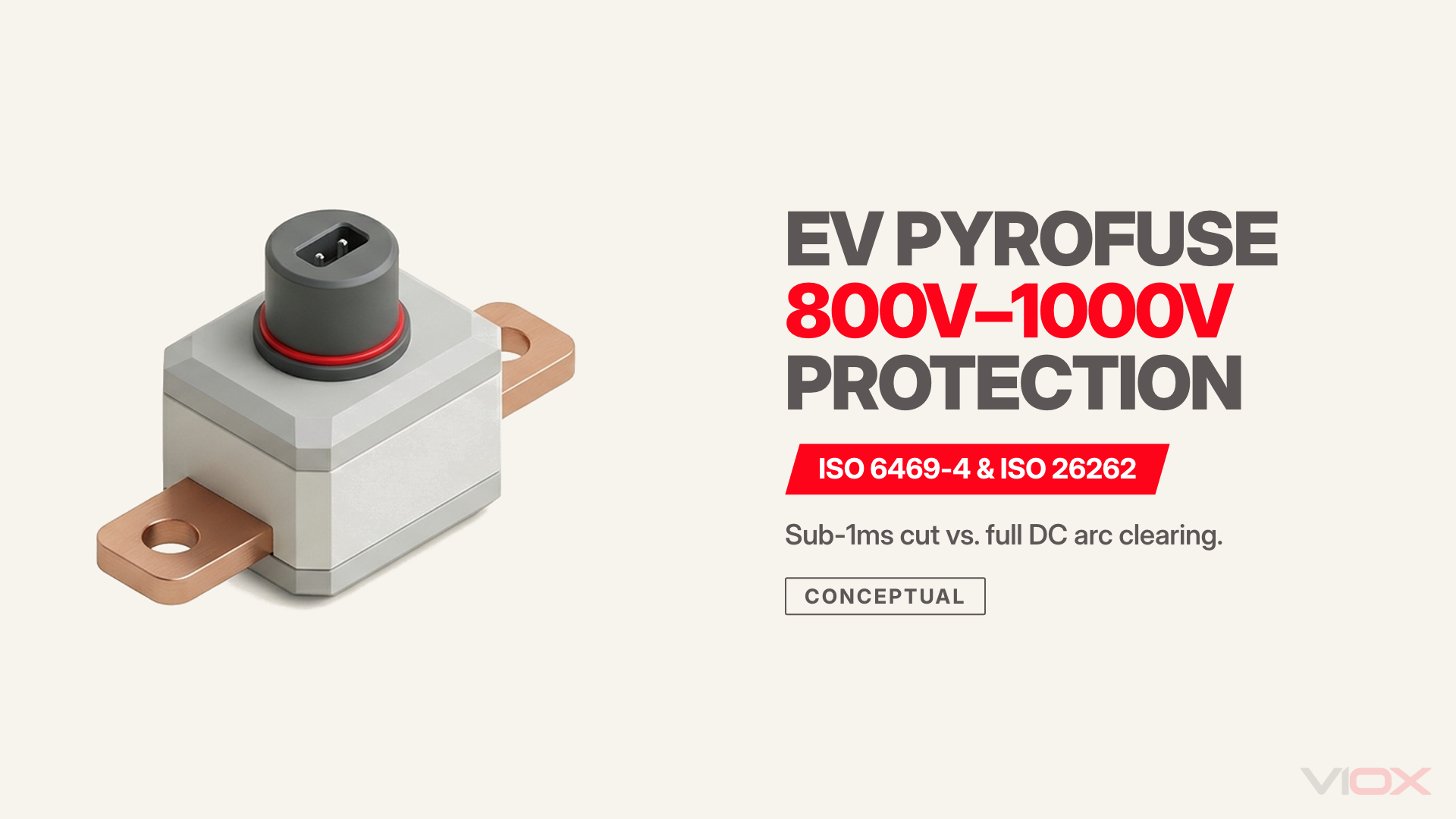
A pyrofuse (also called a pyrotechnic safety switch or pyrotechnic circuit breaker) is an actively triggered, single-use high-voltage disconnect device engineered for electric vehicle (EV) traction batteries. When commanded by a Battery Management System (BMS) or airbag crash controller, an internal micro-gas generator drives an insulating piston through a solid copper busbar—mechanically severing an 800 V to 1,000 V DC circuit in under 1 ms, with full end-to-end DC arc extinction typically completing within 1 to 5 ms.
Engineering Scope: This guide covers on-board automotive high-voltage (Voltage Class B, > 60 V DC up to 1,500 V DC) battery disconnect architecture under ISO 6469-3, ISO 6469-4, ISO 26262, UN ECE Regulation No. 100, and US FMVSS 305 (49 CFR § 571.305). Exact interrupting ratings, squib firing currents, and dielectric hold-off distances are governed by the component manufacturer’s qualification datasheet.
Inside a Pyrofuse: How Squib Ignition Severs an 800V–1000V Busbar
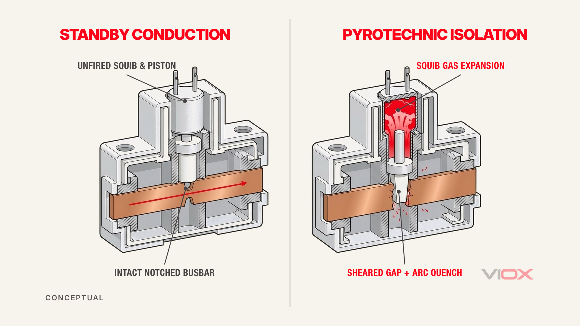
An automotive pyrofuse interrupts high-voltage battery power by converting a low-voltage electronic command into a controlled pyrotechnic mechanical shear rather than waiting for conductor heat to melt metal. Because the cutting action is physically driven by expanding gas inside a sealed chamber, a pyrofuse breaks circuits independently of whether fault current is flowing at the instant of impact.
Inside the sealed housing, four sub-assemblies execute the isolation sequence:
- Solid Copper Busbar with Precision Notch: During normal driving and ultra-fast charging, continuous pack currents (commonly 400 A to 800 A on modern high-voltage platforms) flow through a low-resistance copper busbar machined with calibrated shear zones. Because there are no moving spring contacts in the main current path, steady-state contact resistance and I²R losses remain minimal.
- Micro-Gas Generator (Squib Initiator): Derived from automotive airbag inflator technology, the ignitor receives a controlled firing pulse from a dedicated squib-driver IC when the BMS or Crash Control Unit (CCU) validates a severe collision or runaway short circuit.
- High-Velocity Insulating Piston: Rapid gas expansion accelerates a polymer or ceramic-composite cutting piston downward through the notched busbar, shearing the copper cleanly and wedging solid dielectric material directly into the newly created gap.
- Arc-Quenching Chamber: At 800 V to 1,000 V DC, mechanically separating a current-carrying conductor does not immediately stop electron flow because DC lacks the natural periodic zero-crossings present in AC networks. The insulating wedge lengthens and cools the plasma column while internal arc-extinguishing geometry forces arc voltage above the battery pack voltage until current collapses to zero.
Sub-Millisecond Mechanical Cut vs. Total Fault-Clearing Time
Engineers evaluating EV battery disconnect specifications must separate mechanical busbar severance time (< 1 ms) from total end-to-end fault-clearing time (typically 1 to 5 ms). Treating sub-millisecond actuation as instantaneous zero-current interruption underestimates peak let-through energy (I²t) during high-voltage DC dead shorts.
When a traction pack suffers a low-impedance short circuit at 800 V to 1,000 V DC, prospective fault currents can escalate toward 10 kA to 25 kA within milliseconds. The complete disconnection event unfolds across four sequential stages:
| Disconnection Stage | Physical Action | Typical Time Window | Key Governing Variable |
|---|---|---|---|
| 1. Fault Detection & Validation | BMS current shunt, Hall sensor, or crash accelerometer confirms fault threshold | 0.2 to 2.0 ms | Filtering window vs. false-trip immunity |
| 2. Squib Firing Pulse | Dedicated driver IC injects firing current into initiator bridgewire | 0.1 to 0.5 ms | Ignition energy and squib-loop resistance |
| 3. Mechanical Busbar Severance | Gas expansion drives insulating piston through notched copper busbar | < 1.0 ms | Chamber pressure and busbar shear geometry |
| 4. High-Voltage DC Arc Extinction | Plasma arc elongates and cools until arc voltage exceeds pack voltage | 0.5 to 2.5 ms | Pack voltage (400 V vs. 800 V–1,000 V), circuit inductance (L/R), and fault current |
Specification Rule: Use the < 1 ms mechanical separation metric to verify crash-isolation speed under low or zero load current; always use the full signal-to-zero-current clearing time (1 to 5 ms) and manufacturer I²t let-through curves when coordinating downstream inverter busbars and pack interconnect welds under 10 kA to 25 kA short circuits.
Why 800V–1000V EV Packs Outgrow Melting Fuses and HV Contactors
Moving EV traction architectures from 400 V to 800 V and 1,000 V doubles open-circuit DC voltage and dramatically raises arc-sustaining energy, exposing fundamental physical limits in both passive melting fuses and electromechanical contactors. Neither legacy technology can simultaneously deliver crash-triggered zero-current isolation, weld-free high-fault interruption, and fatigue-free ultra-fast charging.
Three distinct failure boundaries explain why high-voltage EV battery packs require a pyrotechnic disconnect alongside conventional protection:
- HV Contactor Contact Welding Under Fault: High-voltage DC contactors rely on electromagnetic coils and gas-filled chambers with magnetic blowout to open routine loads, typically requiring 5 to 15 ms to separate. As detailed in our engineering breakdown of why DC contactors require specialized arc extinction, DC arcs do not self-extinguish at zero crossings. During a 10 kA+ dead short, electromagnetic Lorentz blow-off forces can momentarily lift closed contactor blades before the coil releases, generating localized plasma that permanently welds the contacts shut—turning the main disconnect into a solid short circuit.
- Passive Melting Fuse Blindness to Structural Crashes: A conventional passive fuse operates solely on thermal energy accumulation (I²t). In a severe vehicle collision where structural deformation threatens high-voltage cabling without immediately creating a dead short, current may remain low or zero—meaning a melting fuse will never open to de-energize damaged cables for occupants and first responders.
- 800V Thermal-Cycling Fatigue in Melting Fuses: Ultra-fast DC charging and aggressive regenerative braking subject traction-pack conductors to thousands of high-current thermal cycles. Sizing a passive melting fuse large enough to survive repeated 400 A to 800 A charging pulses without thermal fatigue slows its melting response during moderate short circuits, creating a protection gap that an actively commanded pyrofuse eliminates. For the underlying thermal physics of passive fuses on DC circuits, see AC fuse vs. DC fuse arc-quenching mechanics.
| Protection Parameter | Pyrofuse (Pyrotechnic Switch) | Passive Melting Fuse | HV DC Contactor |
|---|---|---|---|
| Trigger Mechanism | Active electronic command (BMS / CCU) and optional passive overcurrent self-trigger | Passive thermal I²t melting of fusible element | Active low-voltage coil command |
| Mechanical Break / Clearing Time | < 1 ms mechanical cut; 1 to 5 ms total clearing | Tens of milliseconds to minutes depending on overcurrent ratio | 5 to 15 ms normal opening; unsafe above max breaking limit |
| Breaks Zero-Current Crash Faults | Yes (independent of load current) | No (requires overcurrent heat) | Yes, unless control power is lost or contacts weld |
| High-Fault Weld Risk (10 kA–25 kA) | None (solid busbar sheared apart) | None (element vaporizes in silica sand) | Severe contact-welding risk above rated breaking capacity |
| Resettability & Serviceability | Non-resettable (single-use; workshop replacement) | Non-resettable (single-use replacement) | Resettable (thousands of normal switching cycles) |
Правило отбора: Never replace an HV contactor with a pyrofuse for routine drive-cycle switching, and never rely on an HV contactor alone to interrupt dead shorts above its rated breaking current; assign each device to the fault regime where its physics cannot fail.
Three-Layer Battery Disconnect Unit (BDU) Coordination Architecture
Modern 800 V to 1,000 V EV Battery Disconnect Units (BDUs) resolve the trade-off between resettability, passive reliability, and sub-millisecond emergency cutoff by arranging a pyrofuse, a passive backup fuse, and main HV contactors in series. Each layer owns a non-overlapping electrical and mechanical fault zone so single-point control failures never leave the traction pack unprotected.
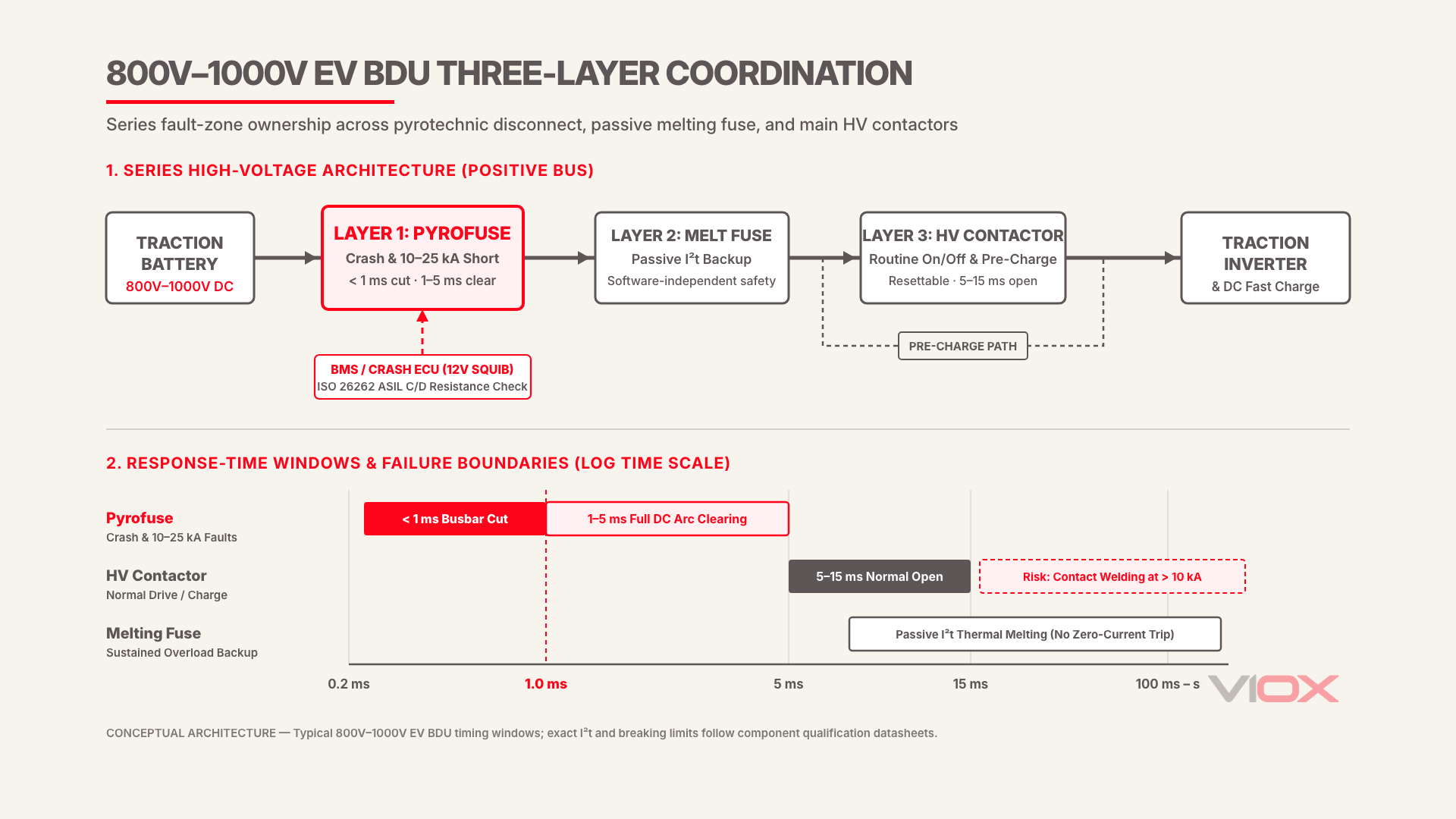
In a coordinated series BDU topology, protection responsibility divides cleanly across four operating events:
| Operating or Fault Event | Primary Acting Device | Backup Layer | Why This Layer Owns the Event |
|---|---|---|---|
| Normal Drive / Charge On-Off & Pre-Charge | Main HV Contactors + Pre-Charge Circuit | BMS diagnostic lockout | Resettable switching over vehicle lifetime without sacrificing single-use devices |
| Sustained Overcurrent (1.5× to 5× Rated Current) | BMS Contactor Opening (if within rating) or Passive Melting Fuse | Pyrofuse via BMS overcurrent trip | Avoids unnecessary irreversible pyrofuse firing for recoverable soft faults while preserving passive I²t backup |
| Severe Vehicle Collision (Airbag Deployment) | Pyrofuse (Commanded by CCU / BMS) | Main HV Contactors opening | Guarantees irreversible physical busbar separation in < 1 ms mechanical time even at zero load current |
| Direct Pack Short Circuit (10 kA to 25 kA at 800 V–1,000 V DC) | Pyrofuse (Active BMS or Dual Self-Trigger) | Passive Melting Fuse (Quartz-Sand Quenching) | Interrupts fault current before HV contactor contacts can blow off and weld shut |
Coordination Rule: Set the BMS pyrofuse overcurrent trigger threshold above the peak traction/fast-charging envelope but safely below the contactor contact-welding threshold, while keeping the series passive melting fuse curve positioned as a software-independent safety net if low-voltage electronics lose power.
Active vs. Dual-Triggering and ISO 26262 Squib-Loop Supervision
Because a standard active pyrofuse depends on external sensing and a 12 V firing circuit to detonate, automotive functional safety engineering under ISO 26262-1 treats the pyrofuse initiation loop as a high-integrity safety path—commonly developed to ASIL C or ASIL D. Two architectural mechanisms prevent either silent failure to fire or catastrophic nuisance detonation while driving.
Active-Only vs. Dual-Trigger (Autonomous) Pyrofuses
An active-only pyrofuse fires exclusively when an external controller (BMS or airbag ECU) sends a validated current pulse to the squib. While compact and cost-effective, it relies on intact low-voltage sensing and driver hardware at the exact millisecond a fault strikes.
A dual-trigger (active + passive/autonomous) pyrofuse integrates an internal current-sensing and self-triggering mechanism directly inside the high-voltage disconnect housing. If a dead short spikes pack current beyond a hard physical threshold while external BMS communication is delayed or disrupted, the device self-triggers independently of vehicle software—while still accepting standard external crash signals from the airbag ECU.
Continuous Squib-Loop Diagnostic Supervision
Under ISO 26262 functional safety lifecycles, a latent open circuit, short-to-ground, or short-to-battery in the squib wiring would disable emergency battery isolation without warning. Dedicated automotive squib-driver ICs continuously inject a tightly limited diagnostic test current—far below the minimum no-fire energy threshold of the ignitor—to measure exact squib-loop resistance (typically on the order of a few ohms). Any drift outside the allowable resistance window triggers an immediate BMS fault flag before the vehicle enters high-voltage driving mode.
Regulatory Boundaries: UN ECE R100 vs. ISO 6469-4 and FMVSS 305
Technical literature frequently misattributes post-crash EV battery disconnection rules exclusively to UN ECE Regulation No. 100. In reality, international Voltage Class B (> 60 V DC to 1,500 V DC) electric-vehicle compliance splits sharply between in-use electrical safety и post-crash shock protection across four distinct regulatory and standards frameworks.
| Standard / Regulation | Primary Jurisdiction | Exact High-Voltage Scope | Post-Crash Isolation Mandate? | Role of Pyrofuse |
|---|---|---|---|---|
| UN ECE Regulation No. 100 | UNECE / Europe & Global Type-Approval | In-use electric powertrain safety and REESS; defines Voltage Class B (> 60 V DC to 1,500 V DC) | НЕТ (Part I explicitly excludes post-crash requirements) | Supports overall REESS overcurrent and safety architecture; crash rules sit in UN R94 / R95 and UN GTR No. 20 |
| ISO 6469-3 | International (ISO) | In-use electrical safety: Voltage Class B barriers, IPXXB protection, insulation resistance, equipotential bonding | No (covers normal operation and servicing) | Defines baseline Class B (> 60 V DC) shock-protection criteria |
| ISO 6469-4 | International (ISO) | Post-crash electrical safety specifications for electrically propelled road vehicles | ДА (requires automatic HV isolation or bus voltage reduction to ≤ 60 V DC / safe residual energy) | Primary actuator achieving rapid irreversible HV bus isolation upon collision |
| FMVSS 305 (49 CFR § 571.305) | United States (NHTSA) | Electrolyte spillage, battery retention, and high-voltage shock protection (> 60 V DC / > 30 V AC), transitioning to § 571.305a | ДА (post-crash low-voltage ≤ 60 V DC, isolation resistance, or physical-barrier compliance options) | Isolates traction pack from chassis harnesses immediately after impact |
Compliance Rule: When documenting crash-triggered pyrofuse requirements for European or international homologation, cite ISO 6469-4 alongside UN R94/R95 or UN GTR No. 20 (and 49 CFR § 571.305 / § 571.305a for the United States)—never cite UN ECE R100 alone as a post-crash disconnection mandate.
On-Board EV Pyrofuses vs. Stationary Charging and BESS Protection
On-board automotive pyrofuses solve a uniquely mobile hazard—violent structural crash impacts combined with compact 800 V to 1,000 V lithium-ion packs—whereas stationary DC fast chargers and utility Battery Energy Storage Systems (BESS) rely on resettable industrial switchgear, high-rupturing-capacity DC fuses, and coordinated surge protection. Confusing automotive BDU architecture with stationary installation codes leads to costly over-specification or non-compliant panel assemblies.
In stationary high-voltage DC infrastructure (such as 1,000 V to 1,500 V DC fast-charging cabinets, solar PV arrays, and containerized BESS racks), equipment is anchored inside rated enclosures governed by IEC 60364, IEC 60269-7, or UL/NFPA installation standards rather than crash-impact regulations. Engineers designing off-board charging cabinets and stationary DC distribution can reference VIOX’s dedicated stationary protection engineering guides:
- For off-board high-power charging cabinets, see overcurrent and overvoltage protection for DC fast chargers.
- For passive high-voltage DC interrupting ratings in stationary strings, see DC fuse breaking capacity for PV and DC systems.
- For stationary battery rack transient overvoltage coordination, see surge protection for BESS (DC, AC, and signal SPD selection).
Вопросы и ответы
Can a pyrofuse be reset after a minor collision or false BMS trigger?
No. A pyrofuse is strictly a single-use, irreversible safety device because the pyrotechnic piston physically shears the internal copper busbar and locks insulating material into the gap. Once deployed—even from a low-speed airbag event or software fault—the pyrofuse assembly must be physically replaced by a qualified high-voltage technician and the BMS fault latch cleared before the traction battery can be re-energized.
How does a pyrofuse fire if the 12V auxiliary battery cable is severed in a crash?
Automotive airbag ECUs and BMS safety controllers incorporate local hold-up energy-reserve capacitors specifically sized to retain enough firing energy for several hundred milliseconds after 12 V supply loss. For direct short-circuit faults where external control paths are compromised, dual-trigger pyrofuses add an autonomous internal overcurrent trigger, while a series passive melting fuse provides a final electronics-independent backup.
Are pyrofuses also used in stationary Battery Energy Storage Systems (BESS)?
Most commercial and utility BESS racks rely on IEC 60269-7 battery melting fuses, DC molded-case circuit breakers (MCCBs), and DC contactors because stationary containers do not experience road collisions and require field serviceability. However, specialized high-energy-density BESS architectures occasionally adopt pyrotechnic disconnect switches at rack or string level when ultra-fast fault-current limitation is required to prevent high-energy arc flash inside compact enclosures.
Источники
- ISO 26262-1:2018 — Road vehicles: Functional safety (Vocabulary and ASIL Framework)
- ISO 6469-3:2021 — Electrically propelled road vehicles: Safety specifications — Part 3: Electrical safety
- ISO 6469-4:2015 — Electrically propelled road vehicles: Safety specifications — Part 4: Post crash electrical safety
- UN ECE Regulation No. 100 — Uniform provisions concerning the approval of vehicles with regard to specific requirements for the electric power train
- 49 CFR § 571.305 (FMVSS No. 305) — Electric-powered vehicles: electrolyte spillage and electrical shock protection (eCFR)