
Какие требования предъявляет IEC 61439 к конструкции низковольтной комплектной аппаратуры?
IEC 61439 устанавливает всеобъемлющие правила проектирования низковольтных комплектных устройств до 1000 В переменного тока или 1500 В постоянного тока, предписывая проверку пределов повышения температуры, стойкости к короткому замыканию, диэлектрических свойств и защиты от поражения электрическим током посредством испытаний, расчетов или сравнения конструкции с эталонными сборками. Стандарт устраняет различие между испытанными комплектными устройствами (TTA) и частично испытанными комплектными устройствами (PTTA), требуя, чтобы все сборки соответствовали одним и тем же критериям безопасности и производительности, независимо от метода проверки.
Основные выводы
- IEC 61439-1:2020 служит стандартом общих правил, применимым ко всем низковольтным комплектным устройствам и устройствам управления до 1000 В переменного тока или 1500 В постоянного тока.
- Три метода проверки принимаются: испытания, расчеты и сравнение с эталонной конструкцией, что обеспечивает гибкость при сохранении строгости безопасности.
- Пределы повышения температуры не должны превышать 105K для голых медных шин и 70K для клемм при номинальном токе, умноженном на коэффициент номинального разнообразия (RDF).
- Стойкость к короткому замыканию проверка является обязательной для всех сборок либо посредством испытаний, расчетов, либо сравнения с испытанной эталонной конструкцией.
- Четкое разделение ответственности существует между первоначальным производителем (проектирование системы) и производителем сборки (окончательное соответствие) в рамках стандарта.
- Коэффициент номинального разнообразия (RDF) позволяет использовать реалистичные допущения по токовой нагрузке — обычно 0,8-1,0 в зависимости от количества отходящих цепей и типа применения.
- Формы внутреннего разделения. (Форма 1 - Форма 4b) определяют уровни локализации дугового пробоя и доступности, критически важные для безопасности персонала.
Понимание серии стандартов IEC 61439
Серия стандартов IEC 61439, которая заменила IEC 60439 в 2009 году, представляет собой фундаментальный сдвиг в том, как проектируются, проверяются и сертифицируются низковольтные комплектные устройства. В отличие от предыдущего стандарта, который создал двухуровневую систему испытанных комплектных устройств (TTA) и частично испытанных комплектных устройств (PTTA), IEC 61439 устанавливает единые требования для всех сборок, независимо от метода проверки.
Стандарт организован в несколько частей:
- IEC 61439-1: Общие правила — Определяет основные требования, применимые ко всем типам сборок, включая требования к конструкции, производительности и проверке.
- IEC 61439-2: Комплектные устройства распределения энергии — Охватывает системы распределения энергии, центры управления двигателями и распределительные щиты.
- IEC 61439-3: Распределительные щиты — Относится к сборкам, предназначенным для эксплуатации обычными лицами (DBO).
- IEC 61439-6: Системы шинопроводов — Определяет требования к шинопроводам, отводным блокам и связанным с ними компонентам.
Эта модульная структура позволяет производителям применять общие правила в сочетании с требованиями, специфичными для конкретного продукта, которые имеют отношение к их применению. Для B2B-производителей, таких как VIOX Electric, понимание того, какие части применимы к конкретным линейкам продуктов, имеет важное значение для соответствия требованиям и доступа к рынку.
Критические требования к конструкции в соответствии с IEC 61439
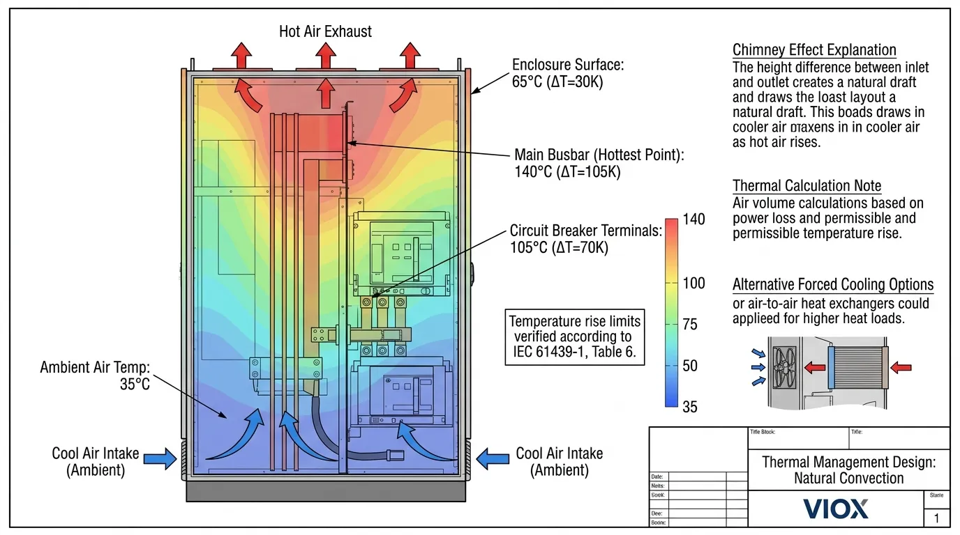
Пределы повышения температуры и управление температурным режимом
Проверка повышения температуры является одним из наиболее важных аспектов соответствия требованиям IEC 61439. Чрезмерное тепло ухудшает изоляцию, ускоряет старение и создает опасность возгорания. Стандарт устанавливает конкретные пределы повышения температуры, которые не должны быть превышены при номинальных токовых условиях.
IEC 61439-1 Таблица 6: Максимальные пределы повышения температуры
| Компонент | Предел повышения температуры (K) | Примечания |
|---|---|---|
| Голые медные шины | 105 | Более высокие пределы для посеребренных или никелированных поверхностей |
| Шины с лужеными соединениями | 90 | Ограничено целостностью паяного соединения |
| Клеммы для внешних изолированных кабелей | 70 | На основе номинала изоляции кабеля (ПВХ/ПЭ) |
| Клеммы для внешних кабелей XLPE | 90 | Более высокая температурная стойкость изоляции XLPE |
| Ручные органы управления (металлические) | 25 | Безопасные для прикосновения поверхности |
| Ручные органы управления (изолирующие) | 35 | Более низкий предел для изоляционных материалов |
| Внешние поверхности корпуса | 30 | Соображения безопасности для соседних материалов |
При проверке повышения температуры учитывается Коэффициент номинального разнообразия (RDF), который признает, что не все цепи работают при полной нагрузке одновременно. Значения RDF варьируются от 1,0 для входящих цепей питания до 0,4 для распределительных щитов со многими отходящими цепями. Этот фактор умножает номинальный ток для расчетов повышения температуры, что позволяет создавать более реалистичные и экономичные конструкции без ущерба для безопасности.
Для управления температурным режимом инженеры должны учитывать:
- Естественную конвекцию через вентиляционные отверстия, расположенные для использования эффекта дымовой трубы
- Принудительное воздушное охлаждение для сборок высокой плотности, превышающих 6300 А
- Рассеивание тепла от автоматические выключатели и других компонентов на основе данных о потерях мощности IEC 60947
- Снижение номинальных характеристик при температуре окружающей среды, когда установки превышают стандартную эталонную температуру 35°C
Проверка стойкости к короткому замыканию
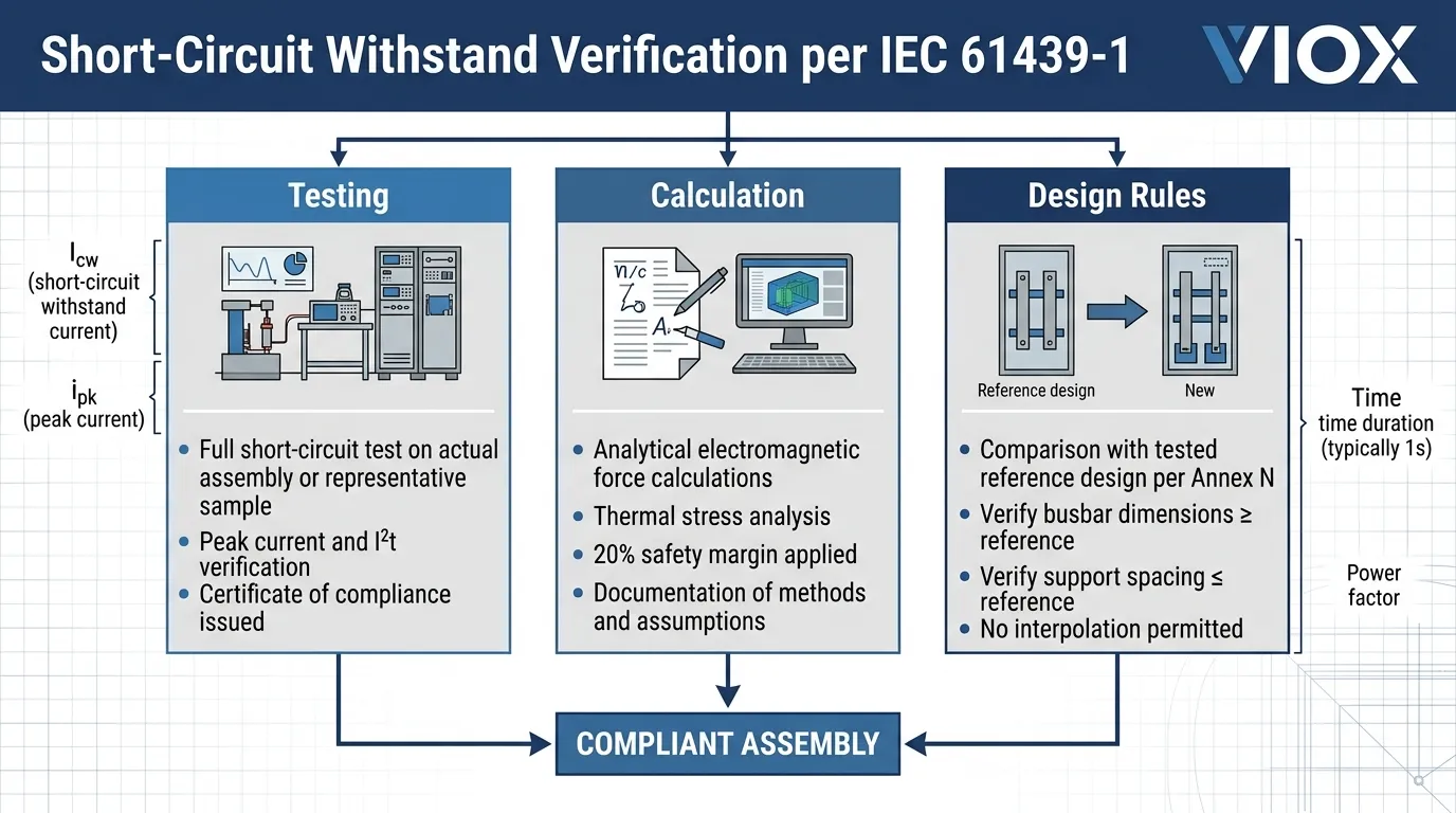
IEC 61439 требует, чтобы все сборки выдерживали механические и тепловые нагрузки токов короткого замыкания. Номинальный ток короткого замыкания сборки (Icw) представляет собой максимальный ток, который сборка может безопасно проводить в течение определенного времени (обычно 1 секунда) без повреждений.
Варианты проверки:
- Тестирование — Полное испытание на короткое замыкание на фактической сборке или репрезентативном образце
- Расчет — Аналитическая проверка с использованием признанных инженерных методов с запасом прочности
- Сравнение с эталонным проектом — Сравнение с протестированным эталонным проектом с равными или большими параметрами
Проверка на короткое замыкание должна учитывать:
- Стойкость к пиковому току (связана с Icw через коэффициент “n”, обычно 1,5-2,1 в зависимости от коэффициента мощности)
- Тепловое воздействие (I²t) через характеристики отключения защитного устройства
- Электромагнитные силы между проводниками, особенно для шинопроводы без надлежащего крепления
- Координация с защитными устройствами для обеспечения защиты сборки в условиях неисправности
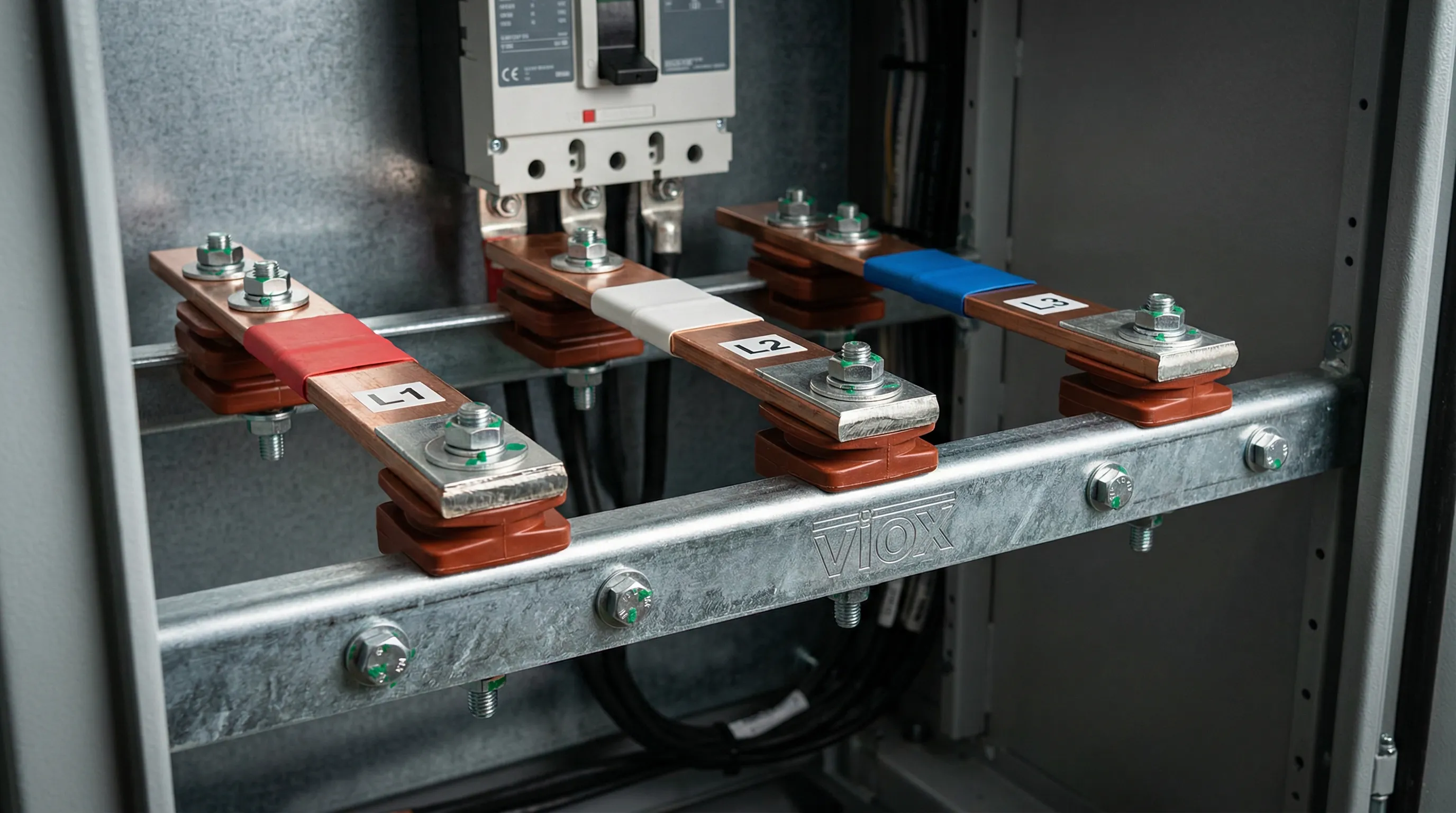
Для систем медных шин требования к расстоянию и опоре имеют решающее значение. IEC 61439 допускает проверку прочности шин на короткое замыкание по расчету или сравнению с протестированными эталонными проектами, при условии, что все критерии, включая размеры проводника, расстояние и расположение опор, соответствуют или превышают эталонные.
Диэлектрические свойства и зазоры
Координация изоляции обеспечивает устойчивость сборок к рабочим напряжениям, временным перенапряжениям и переходным перенапряжениям. IEC 61439 определяет:
Минимальные зазоры и пути утечки:
| Номинальное напряжение изоляции (В) | Минимальный зазор по воздуху (мм) | Минимальный путь утечки (мм) — Степень загрязнения 3 |
|---|---|---|
| ≤ 300 | 5.5 | 8.0 |
| 300-600 | 8.0 | 12.0 |
| 600-1000 | 14.0 | 20.0 |
Стандарт требует, чтобы сборки выдерживали:
- Испытания на выдерживаемое напряжение промышленной частоты (обычно 2 кВ переменного тока в течение 1 секунды для систем 400 В)
- Испытания на выдерживаемое импульсное напряжение (8 кВ для систем 400 В в категории перенапряжения III)
- Проверка поддержания зазоров во время сборки и в течение всего срока службы
Разработчики должны учитывать снижение номинальных характеристик по высоте — зазоры должны увеличиваться примерно на 11% на каждые 100 м выше 2000 м. Это особенно важно для распределительных устройств, предназначенных для установки на большой высоте.
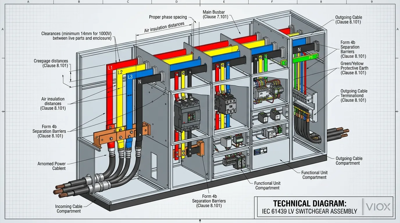
Формы внутреннего разделения: Локализация дугового пробоя
IEC 61439 определяет Формы внутреннего разделения которые определяют степень разделения между шинами, функциональными блоками и клеммами. Эти формы варьируются от формы 1 (без разделения) до формы 4b (разделение шин, функциональных блоков и клемм, включая соединения между блоками).
| Форма | Разделение шин | Разделение функциональных блоков | Разделение клемм | Приложение |
|---|---|---|---|---|
| Форма 1 | Никто | Никто | Никто | Простое распределение, минимальные требования безопасности |
| Форма 2a | ДА | Никто | Никто | Базовая изоляция шин |
| Форма 2b | ДА | Никто | ДА | Разделение доступа к клеммам |
| Форма 3a | ДА | Да, без клемм | Никто | Центры управления двигателями с ограниченным разделением |
| Форма 3b | ДА | Да, без клемм | ДА | Стандартное промышленное распределительное устройство |
| Форма 4a | ДА | Да, включая клеммы | Да (в одном отсеке) | Высоконадежное разделение |
| Форма 4b | ДА | Да, включая клеммы | Да (в отдельных отсеках) | Максимальная безопасность, критически важные приложения |
Более высокие номера форм обеспечивают большую локализацию дугового пробоя и защиту персонала, но увеличивают стоимость и сложность. Форма 4b, например, требует отдельных отсеков для клемм каждого функционального блока, что существенно влияет на конструкцию корпуса и рассеивание тепла.
Выбор формы разделения включает в себя балансировку:
- Требования безопасности (доступ персонала, локализация дугового пробоя)
- Потребности в обслуживании (доступность для обслуживания отдельных блоков)
- Тепловое управление (разделение может препятствовать воздушному потоку)
- Ограничения по стоимости (более высокие формы требуют больше материала и сложной конструкции)
- Критичность применения (центры обработки данных, больницы обычно указывают форму 4)
Методы проверки: Испытания, расчет и правила проектирования
IEC 61439 предоставляет три пути проверки, признавая, что полное тестирование каждого варианта сборки нецелесообразно:
Проверка путем испытаний
Традиционный подход, при котором фактическая сборка подвергается лабораторным испытаниям. Требуется для:
- Превышение температуры (если не применяются правила проектирования)
- Стойкость к короткому замыканию (если не применяются расчеты или правила проектирования)
- Диэлектрические свойства
- Механической работы
- Степень защиты (проверка IP)
Проверка расчетом
Аналитические методы, разрешенные для определенных характеристик:
- Превышение температуры с использованием теплового моделирования с проверенными данными
- Стойкость к короткому замыканию с использованием расчетов электромагнитной силы
- Проверка путей утечки и воздушных зазоров посредством размерного анализа
В расчетах должны использоваться признанные инженерные методы с соответствующими запасами прочности. Стандарт требует консервативных допущений — номинальные характеристики устройства должны быть снижены на 20% при использовании в расчетах, если нет конкретных данных по компонентам.
Проверка правилами проектирования
Сравнение с протестированными эталонными проектами:
- Разрешено для стойкости к короткому замыканию, когда поперечные сечения шин, материалы и расстояние между опорами соответствуют или превышают эталонные
- Приложение N стандарта IEC 61439-1 содержит конкретные параметры правил проектирования для шинных систем
- Эталонный проект должен быть протестирован на том же или более высоком уровне нагрузки
- Все параметры должны быть равны или превосходить эталонные — интерполяция не допускается
Этот подход особенно ценен для систем магистральных шинопроводов и стандартизированных диапазонов распределительных устройств, где несколько конфигураций имеют общие принципы конструкции.
Структура ответственности: Первоначальный производитель против производителя сборки
IEC 61439 четко разграничивает обязанности между двумя ключевыми организациями:
Первоначальный производитель (производитель системы):
- Разрабатывает систему распределительного устройства
- Устанавливает правила проектирования и методы проверки
- Предоставляет протестированные эталонные проекты
- Определяет компоненты, материалы и методы строительства
- Выпускает системную документацию и руководство по соответствию
Производитель сборки (сборщик панелей):
- Собирает конечное распределительное устройство
- Проверяет соответствие стандарту с использованием методов, предоставленных Первоначальным производителем
- Выполняет рутинную проверку (рутинные испытания каждой сборки)
- Несет ответственность за готовую сборку, размещенную на рынке
- Ведет техническую документацию и Декларацию соответствия
Эта структура гарантирует, что, хотя опыт проектирования системы находится у Первоначального производителя, ответственность за готовый продукт лежит на Производителе сборки. Для специалистов по закупкам понимание этого различия имеет важное значение при оценке заявлений поставщиков о соответствии.
Практическая реализация: Контрольный список проектирования для инженеров
Этап предварительного проектирования
- Определите требования к применению — Напряжение, ток, уровень тока короткого замыкания, условия окружающей среды
- Выберите соответствующую часть IEC 61439 — -2 для силовых распределительных устройств, -3 для распределительных щитов, -6 для магистральных шинопроводов
- Определите номинальный коэффициент разнообразия — На основе характеристик нагрузки и количества цепей
- Установите требуемую форму разделения — На основе требований безопасности и критичности применения
- Определите применимые понижающие коэффициенты — Температура, высота над уровнем моря, гармоники, условия установки
Этап проектирования
- Рассчитайте размер шины — На основе номинального тока, RDF, пределов повышения температуры и материала шины
- Проверьте стойкость к короткому замыканию — Испытание, расчет или сравнение с эталонным проектом
- Определите воздушные зазоры и пути утечки — На основе номинального напряжения изоляции и степени загрязнения
- Разработайте систему управления температурным режимом — Естественная вентиляция, принудительное охлаждение или кондиционирование воздуха
- Выберите степень защиты корпуса — Степень защиты IP на основе окружающей среды, степень защиты IK от механического воздействия
- Спланируйте внутреннее разделение — Форма от 1 до 4b на основе требований безопасности
Этап проверки
- Проведите проверку проекта — Испытания, расчет или правила проектирования, в зависимости от обстоятельств
- Выполнять плановые испытания — Диэлектрические испытания, проверка проводки, целостности цепи и механической работы каждой сборки
- Составлять техническую документацию — Чертежи, спецификации, отчеты об испытаниях, оценка рисков
- Выпускать Декларацию соответствия — Документация для маркировки CE для доступа на рынок ЕС
Распространенные ошибки проектирования и способы их избежать
Ошибка 1: Игнорирование расчетного коэффициента одновременности нагрузки (Rated Diversity Factor)
Выпуск: Проектирование всех шин для одновременной работы при полной нагрузке приводит к созданию систем с завышенными характеристиками и высокой стоимостью.
Решение: Применяйте соответствующие значения RDF — 0,9-1,0 для входящих цепей, 0,8 для распределения электроэнергии, 0,6-0,7 для распределительных щитов с большим количеством цепей.
Ошибка 2: Недостаточное управление температурным режимом
Выпуск: Опора на теоретические расчеты без учета условий установки (закрытые помещения, солнечное излучение, близлежащие источники тепла).
Решение: Выполняйте тепловое моделирование с реалистичными граничными условиями; указывайте принудительную вентиляцию для сборок высокой плотности; обеспечьте достаточный зазор вокруг корпусов.
Ошибка 3: Несоответствие номинала по току короткого замыкания
Выпуск: Номинал Icw сборки превышает отключающую способность защитного устройства или недостаточная фиксация для электродинамических сил.
Решение: Убедитесь, что автоматический выключатель отключающая способность равна или превышает номинал устойчивости сборки; убедитесь, что расстояние между опорами шин соответствует требованиям правил проектирования.
Ошибка 4: Пренебрежение проверкой зазоров
Выпуск: Предположение стандартных зазоров без учета допусков при установке, разбухания материала или перемещения проводника в условиях короткого замыкания.
Решение: Проектируйте с запасом — указывайте зазоры на 20% больше минимальных требований; проверяйте физическим осмотром во время сборки прототипа.
Ошибка 5: Несовместимость формы секционирования
Выпуск: Указание высоких форм секционирования (Форма 4) без учета теплового воздействия компартментализации.
Решение: Оцените требования к управлению температурным режимом на раннем этапе; укажите вентиляцию или охлаждение для сборок Формы 3 и 4; рассмотрите вентиляция электрической панели стратегии.
Краткий раздел часто задаваемых вопросов
В: В чем разница между стандартом IEC 61439 и старым стандартом IEC 60439?
О: IEC 61439 заменил IEC 60439 в 2009 году и устраняет различие между сборками, прошедшими типовые испытания (Type-Tested Assemblies, TTA), и сборками, частично прошедшими типовые испытания (Partially Type-Tested Assemblies, PTTA). Согласно IEC 61439, все сборки должны соответствовать одинаковым требованиям безопасности независимо от метода проверки (испытания, расчет или правила проектирования). Новый стандарт также вводит более четкое разделение ответственности между производителями оригинального оборудования (Original Manufacturers) и производителями сборок (Assembly Manufacturers) и устанавливает концепцию расчетного коэффициента одновременности нагрузки (Rated Diversity Factor, RDF) для реалистичных расчетов нагрузки.
В: Могу ли я использовать IEC 61439 для проектирования распределительных устройств постоянного тока?
О: Да, IEC 61439-1:2020 явно включает требования для применений постоянного тока до 1500 В постоянного тока. Однако постоянный ток создает уникальные проблемы, включая непрерывное образование дуги во время коротких замыканий (отсутствие естественного перехода тока через ноль), более высокий подъем температуры из-за отсутствия перераспределения скин-эффекта и различные требования к расстоянию утечки. Для применений постоянного тока обратите особое внимание на Автоматический выключатель постоянного тока выбор, конструкцию дугогасительной камеры и соображения полярности.
В: Как определить правильный расчетный коэффициент одновременности нагрузки (RDF) для моей сборки распределительного устройства?
О: RDF зависит от количества отходящих цепей и типа применения. IEC 61439-1 предоставляет справочные значения: 1,0 для входящих цепей питания; 0,9 для 2-3 отходящих цепей; 0,8 для 4-5 цепей; 0,7 для 6-9 цепей; и 0,6 для 10+ цепей. Распределительные щиты (Distribution Boards, DBOs) согласно IEC 61439-3 используют другие критерии, основанные на разнообразии подключенной нагрузки. Всегда документируйте основу для выбора RDF в техническом файле.
В: Требуется ли сертификация третьей стороной для соответствия IEC 61439?
О: Нет, IEC 61439 не требует обязательной сертификации третьей стороной. Стандарт работает на основе самосертификации производителем сборки (Assembly Manufacturer), который берет на себя ответственность за соответствие. Однако многие спецификации (особенно в нефтегазовой отрасли, центрах обработки данных и критической инфраструктуре) требуют проверки третьей стороной через такие органы, как UL, IECEx или уполномоченные органы для маркировки CE. Хотя это и не является обязательным, сертификация третьей стороной обеспечивает независимую проверку заявлений о соответствии.
В: Какие плановые испытания должны проводиться на каждой сборке IEC 61439?
О: Каждая сборка должна пройти плановые испытания перед отправкой: испытание изоляции (диэлектрическая прочность при 1 кВ переменного тока или 1,5 кВ постоянного тока в течение 1 секунды); проверка целостности защитных цепей (максимум 0,05 Ом между корпусом и клеммой заземления); осмотр проводки и установки компонентов; и проверка механической работы (переключатели, автоматические выключатели, блокировки). Результаты испытаний должны быть зарегистрированы и сохранены в техническом файле.
В: Как IEC 61439 рассматривает опасности, связанные с дуговым пробоем?
О: Хотя IEC 61439 конкретно не требует испытаний на локализацию дугового пробоя (см. IEC TR 61641 для этого), формы внутреннего секционирования (Form 2b - 4b) обеспечивают степени локализации дугового пробоя. Форма 4b предлагает наивысшую защиту с полной компартментализацией. Для применений, требующих подтвержденной локализации дугового пробоя (например, в нефтегазовой отрасли), укажите соответствие как IEC 61439, так и IEC TR 61641, который предоставляет методы испытаний для классификации внутренней дуги (Internal Arc Classification, IAC).
Заключение: Инженерное совершенство благодаря соответствию стандартам
IEC 61439 представляет собой зрелую, всеобъемлющую основу для проектирования низковольтных распределительных устройств, которая уравновешивает строгость безопасности с инженерной практичностью. Предоставляя несколько путей проверки — испытания, расчет и правила проектирования — стандарт учитывает разнообразные потребности производителей нестандартных панелей и массовых производителей, сохраняя при этом последовательные критерии безопасности.
Для инженеров-электриков и специалистов по закупкам понимание IEC 61439 — это не просто проставление галочек в списке соответствия. Требования стандарта к управлению температурой, устойчивости к короткому замыканию и внутреннему секционированию напрямую влияют на надежность оборудования, срок службы и безопасность персонала. Правильное применение расчетного коэффициента одновременности нагрузки может привести к значительной экономии средств без ущерба для производительности, а правильная спецификация форм секционирования обеспечивает надлежащую защиту для среды применения.
По мере того, как сборки распределительных устройств становятся все более сложными — интегрируя интеллектуальный мониторинг, защита от перенапряжений, и интерфейсы возобновляемых источников энергии — основные требования IEC 61439 остаются важными. Структура проверки конструкции стандарта, разграничение ответственности и контрольные показатели производительности обеспечивают техническую основу, на которой строятся современные системы распределения электроэнергии.
Для B2B-производителей, таких как VIOX Electric, соответствие IEC 61439 является как требованием доступа к рынку, так и конкурентным преимуществом. Сборки, разработанные и проверенные в соответствии с этим стандартом, демонстрируют инженерную строгость, приверженность безопасности и готовность к глобальному рынку — качества, которые специалисты по закупкам ставят в приоритет при выборе партнеров для проектов критической инфраструктуры.
Техническая справка: Данное руководство основано на IEC 61439-1:2020 “Низковольтные комплектные распределительные устройства и устройства управления. Часть 1. Общие правила” и связанных с ним частях, относящихся к конкретным продуктам. Для получения полных требований соответствия всегда обращайтесь к полному тексту стандарта и применимым национальным отклонениям. Как B2B-производитель оборудования для защиты электрооборудования, VIOX Electric предоставляет компоненты, соответствующие IEC 61439, и техническую поддержку производителям сборок распределительных устройств по всему миру.
