Nesta página
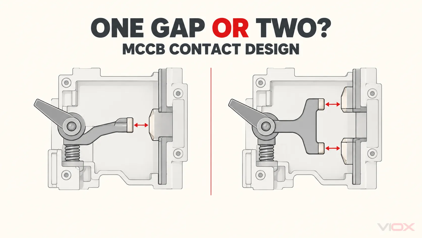
Um single-break MCCB opens one interruption point per pole, enquanto um double-break MCCB opens two interruption points in series per pole. Two gaps change the possible arc path, contact mechanism, and arc-chamber arrangement. They do não, by themselves, prove that a breaker has a higher short-circuit rating, lower let-through energy, longer electrical life, or a particular arc-gas vent direction.
The practical rule is simple: use the contact topology to understand the design, then use the exact breaker’s tested ratings, let-through data, installation instructions, and clearance requirements to make the engineering decision.
If you need the device-level context first, start with what an MCCB is and what it protects. This article stays focused on the narrower question of contact topology inside each pole.
| Errada | What the topology tells you | What requires exact product evidence |
|---|---|---|
| How many interruption points open in one pole? | One for single-break; two in series for double-break | Confirm the actual construction if the manufacturer does not identify it |
| How many primary arcs can form as the contacts separate? | One, or two in series | Arc motion, duration, stability, and final interruption behavior |
| Can the arrangement affect total arc voltage? | Yes; series arcs can contribute to the total arc voltage | The resulting peak current and let-through energy |
| Does double-break mean higher Icu or Ics? | Nenhum | Published Icu and Ics at the applicable voltage |
| Does the topology determine vent direction? | Nenhum | Vent drawings, clearance tables, terminal covers, and barrier requirements |
| Does it determine service life, size, or cost? | Nenhum | Endurance data, dimensions, catalogue configuration, and commercial offer |
How to Identify Single-Break and Double-Break Contacts
A palavra break describes the number of places where the conducting path is interrupted when one pole opens. It does not describe the number of poles.
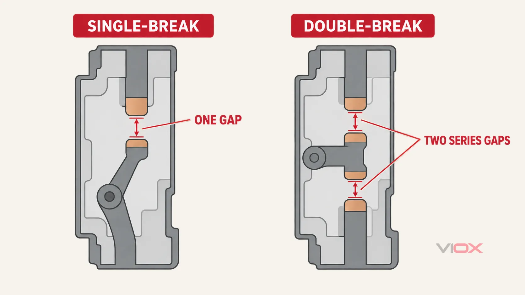
In a single-break pole, one moving contact separates from one fixed contact and creates one interruption gap. Current passes through that contact interface while the breaker is closed. When the mechanism opens, an arc forms across the separating gap and is driven into an arc-control structure.
In a common double-break arrangement, a moving bridge connects two fixed contacts while the breaker is closed. When the bridge moves away, both contact interfaces open, producing two interruption gaps in series within the same pole. Other mechanical arrangements are possible, so the functional definition—two series interruption points—is more reliable than assuming one exact internal shape.
Do not confuse this distinction with a single-pole versus double-pole breaker. Pole count describes how many circuit conductors the device switches or protects. Break count describes how many interruption points exist inside each pole. The broader MCCB internal-parts guide shows where the contact system, operating mechanism, trip unit, and arc chamber sit within the breaker.
What Happens When the Contacts Open
Opening a fault current is not the same as opening an unloaded mechanical switch. As the contacts separate, the current continues through an ionized arc. The breaker must move, cool, lengthen, and divide that arc so that current interruption and dielectric recovery can occur without the case or adjacent insulation failing.
Arc chutes use conductive splitter plates and carefully shaped current paths to raise arc voltage and remove energy from the plasma. Open-access MCCB research describes current limitation as a process of raising arc voltage, with splitter plates contributing additional voltage drops as the arc is divided. For a fuller explanation of the parts involved, see how an arc works in a circuit breaker.
The useful causal chain is:
- The trip and opening mechanism separate the contacts.
- One or two primary arcs form, depending on the contact topology.
- Electromagnetic forces and arc-runner geometry move the arc toward the extinguishing structure.
- The chamber lengthens, cools, and divides the arc while pressure rises inside the molded case.
- The complete pole design—not the number of breaks alone—determines the measured current-limiting and interruption performance.
Why Two Series Breaks Can Matter
With two interruption points, two arcs can exist in series. Their instantaneous voltages contribute to the voltage developed across the pole. In principle, this gives the designer another way to build arc voltage and distribute the interruption process across the pole.
But “two arcs” is not a performance certificate. Contact opening speed, gap development, contact force, arc-runner geometry, splitter-plate use, chamber volume, venting, insulating materials, and the operating mechanism all affect the result. Published benchmark research has therefore compared complete single-break and double-break MCCBs under test conditions rather than treating the topology label as a sufficient result.
What the Contact Topology Cannot Prove
The strongest improvement to an MCCB specification is often knowing what não to infer.
Icu e Ics
Rated ultimate short-circuit breaking capacity (Icu) and rated service short-circuit breaking capacity (Ics) are declared and tested product ratings. They must be checked at the applicable operational voltage. A double-break device does not automatically have a higher rating, and a single-break device is not automatically limited to a lower fault level.
A edição atual da IEC 60947-2 applies to covered low-voltage circuit breakers and defines the relevant circuit-breaker framework. The IEC catalogue notes that the 2024 edition removed classification according to interrupting medium and design from its classification clause. Regardless of the internal contact layout, Icu and Ics remain ratings to verify for the exact breaker at the applicable voltage.
For the meaning and use of the ratings themselves, see Icu vs Ics vs Icw vs Icm.
Peak Let-Through and I²t
Current limitation must be read from manufacturer let-through curves or tables for the exact breaker, voltage, and fault condition. The number of breaks alone cannot supply a credible peak let-through value or I²t value. Generic kA tables that assign one range to single-break devices and another to double-break devices hide the influence of frame size, chamber design, operating speed, and test conditions.
Selectivity and Coordination
Selectivity is a relationship between upstream and downstream protective devices under defined settings and fault conditions. It is verified with manufacturer coordination data or an engineering study. Contact topology may be one internal contributor to device behavior, but it cannot replace a selectivity table.
Electrical Endurance, Size, Reliability, and Cost
Two contact interfaces may distribute some physical effects while adding mechanism and contact-interface requirements. One interface may simplify parts of the mechanism while concentrating interruption in one primary region. Neither observation supports a universal ranking for endurance, reliability, case size, or price. Those outcomes belong to the exact product design and its published evidence.
Arc-Gas Venting and Enclosure Clearance
Arc interruption creates hot gas, vaporized material, and a rapid pressure rise inside the chamber. Experimental research has shown that hot gas associated with MCCB interruption can remain electrically conductive enough to create an arcing risk under certain conditions. The breaker case must therefore provide a controlled path for pressure and gases, while the surrounding assembly must maintain the clearances and insulation measures required by the product instructions.
Contact and chamber architecture can influence where vents can be placed, but it does not establish the final vent direction. Some designs exhaust near one end of the device; others may require clearance at more than one side; engineered channels can also alter the path. The correct answer is always specific to the breaker family, frame, terminals, accessories, voltage, and mounting arrangement.
For panel layout, verify all of the following:
- the location of every arc-gas or pressure-relief opening;
- minimum distance to grounded metal, adjacent breakers, and enclosure surfaces;
- minimum distance to bare busbars, lugs, or other live parts;
- required phase barriers, terminal covers, insulation screens, or rear plates;
- whether an accessory changes the required clearance;
- permitted mounting orientations and any orientation-specific limits;
- the manufacturer’s conditions for side-by-side or vertically stacked devices.
Do not block a vent or improvise a barrier. A generic plastic sheet is not a substitute for a tested accessory or an assembly design validated for the intended fault duty. Exact dimensions belong in the manufacturer’s current installation instructions, not in a universal single-break-versus-double-break rule.
The Architecture-to-Evidence Verification Path
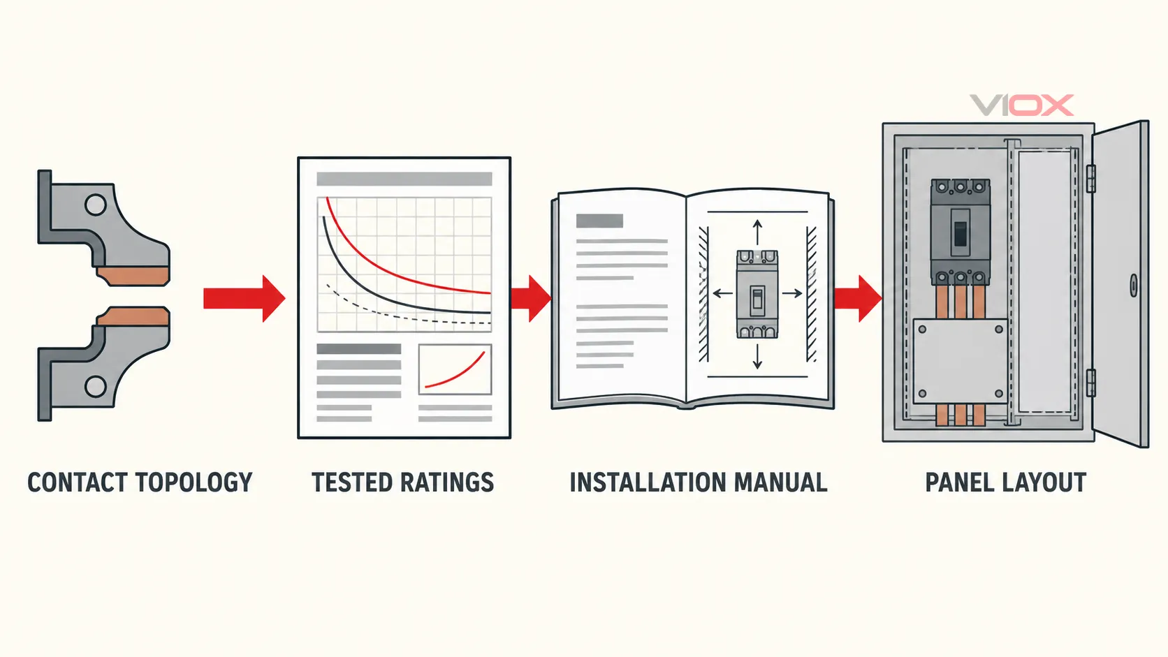
Use the following sequence when evaluating an MCCB:
- Identify the topology. Record whether the pole uses one interruption point or two in series if the information is available.
- Read the tested ratings. Verify operational voltage, Icu, Ics, and any applicable current-limiting data for the exact catalogue reference.
- Check the performance curves. Use peak let-through, I²t, time-current, and coordination information only when published for the relevant combination.
- Read the installation instructions. Locate vent paths, clearances, barriers, terminal arrangements, mounting limits, and enclosure conditions.
- Verify the panel design. Confirm that the actual busbar, cable, enclosure, spacing, and assembly arrangement satisfy those instructions and the applicable project requirements.
This order prevents two common errors: treating an internal architecture as a guaranteed performance class, and selecting a correctly rated breaker without providing the space or insulation measures required for its installation.
Which Design Should You Choose?
Do not begin with “single-break or double-break?” Begin with the system requirements and compare actual products.
Use a MCCB selection workflow to define the system voltage, design current, conductor protection, prospective short-circuit current, poles, trip functions, coordination objective, environment, mounting, terminals, and accessories. Then compare candidates using their published evidence.
Choose the candidate that satisfies the required ratings and installation conditions. If two candidates both meet the duty, contact topology may help explain their construction, but the final comparison should still use:
- Icu and Ics at the system voltage;
- peak let-through and I²t data where current limitation matters;
- time-current and selectivity documentation;
- electrical and mechanical endurance data;
- dimensions, terminals, vents, and required clearances;
- approved barriers, covers, and mounting configuration;
- certification and project-documentation requirements.
O linha de MCCB VIOX can be evaluated using the same checklist. Request the exact datasheet and installation documentation for the catalogue configuration under consideration rather than relying on the words “single-break” or “double-break” as a substitute for evidence.
Fontes
- IEC 60947-2:2024 — Conjuntos de manobra e comando de baixa tensão, Parte 2: Disjuntores
- Benchmark Tests of Single-Break and Double-Break Design Principles — IEEE Holm Conference record
- Computational study of splitter plates and blow-out coil voltage in an MCCB arc chamber
- Experimental study on arcing conditions in hot air associated with circuit-breaker interruption