
Introdução
An electrical contactor is a specialized switching device designed to control high-power electrical circuits safely and efficiently. Unlike standard switches, contactors use electromagnetic principles to open and close electrical connections, making them essential components in industrial automation, motor control, and commercial electrical systems.
Understanding what a contactor is and how it works is crucial for anyone involved in electrical systems, from engineers and technicians to facility managers. This comprehensive guide will explain everything you need to know about electrical contactors, their applications, and why they’re indispensable in modern electrical installations.
What Is A Contactor?

A contactor is an electromechanical switching device that uses an electromagnetic coil to control the opening and closing of electrical contacts, enabling safe control of high-power circuits. The device serves as an electrically operated switch, allowing low-voltage control circuits to safely manage high-voltage, high-current electrical loads.
Key Characteristics of Contactors:
- Remote operation: Can be controlled from a distance using low-voltage signals
- Elevada capacidade de corrente: Designed to handle substantial electrical loads (typically above 10 amperes)
- Frequent switching: Built for thousands of on/off cycles without degradation
- Safety isolation: Provides electrical separation between control and power circuits
- Electromagnetic operation: Uses magnetic force for reliable contact actuation
How Does A Contactor Work?
The operating principle of a contactor is based on electromagnetic attraction and spring-return mechanisms:
Step-by-Step Operation:
- Energization: When voltage is applied to the contactor coil (typically 24V, 120V, or 240V), it creates a magnetic field
- Magnetic attraction: The magnetic field attracts a movable iron core (armature) toward the fixed electromagnetic core
- Contact closure: The armature movement forces the moving contacts against the fixed contacts, completing the circuit
- Current flow: Electrical current can now flow through the main contacts to power the connected load
- De-energization: When coil power is removed, the magnetic field collapses
- Spring return: Spring force pulls the armature back, opening the contacts and interrupting current flow
Electromagnetic Components:
Coil/Electromagnet: The heart of the contactor, creating the magnetic field when energized
Armature: The movable iron core that responds to the magnetic field
Contactos: Conductive elements that make or break the electrical connection
Springs: Provide the return force to open contacts when the coil is de-energized
Tipos de contactores
Contactores AC
AC contactors are designed specifically for alternating current applications and are the most commonly used type in commercial and industrial settings.
Caraterísticas principais:
- Laminated core construction: Uses silicon steel laminations to reduce eddy current losses
- Supressão de arco: Incorporates arc chutes and magnetic blowout to extinguish arcs quickly
- Three-phase capability: Typically designed to control three-phase motor circuits
- Tensão nominal: Available from 120V to 1000V+
Aplicações comuns:
- Electric motor control (pumps, fans, compressors)
- HVAC system switching
- Sistemas de controlo da iluminação
- Industrial machinery automation
Contactores DC
DC contactors handle direct current loads and feature specialized design elements to manage the unique challenges of DC switching.
Caraterísticas principais:
- Solid steel core: Uses solid ferromagnetic materials since eddy currents aren’t a concern
- Enhanced arc suppression: Requires more robust arc extinction methods due to continuous current
- Magnetic blowout: Often includes magnetic blowout coils to direct arcs away from contacts
- Higher contact gap: Larger separation distances to ensure reliable arc extinction
Aplicações comuns:
- Solar power systems and battery banks
- DC motor control (elevators, cranes)
- Electric vehicle charging systems
- Railway and transit applications
Specialized Contactor Types
- Contactores de inversão: Feature dual contact sets to reverse motor rotation direction safely
- Lighting Contactors: Optimized for resistive loads with latching mechanisms for energy efficiency
- Capacitor Contactors: Designed for switching power factor correction capacitors
- Vacuum Contactors: Use vacuum-sealed contacts for medium and high-voltage applications
Contactor vs Relay: Understanding the Differences
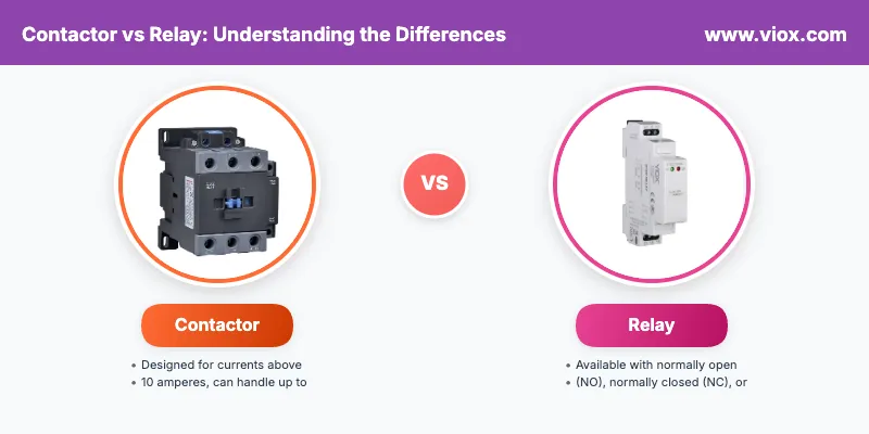
While contactors and relays operate on similar electromagnetic principles, they serve different purposes and have distinct characteristics:
Capacidade de carga
- Contactors: Designed for currents above 10 amperes, can handle up to thousands of amperes
- Relés: Typically rated for currents of 10 amperes or less
Configuração dos contactos
- Contactors: Primarily use normally open (NO) contacts that close when energized
- Relés: Available with normally open (NO), normally closed (NC), or changeover contacts
Physical Size and Construction
- Contactors: Larger, more robust construction to handle high-power loads
- Relés: Compact design suitable for control circuit applications
Supressão de arco
- Contactors: Include sophisticated arc suppression mechanisms for high-current switching
- Relés: Minimal arc suppression since they handle lower currents
Aplicações
- Contactors: Motor control, lighting systems, heavy industrial loads
- Relés: Signal switching, control logic, low-power device control
Caraterísticas de segurança
- Contactors: Often include overload protection and additional safety contacts
- Relés: Basic switching function without additional protection features
Contactor Applications and Uses
Motor Control Systems
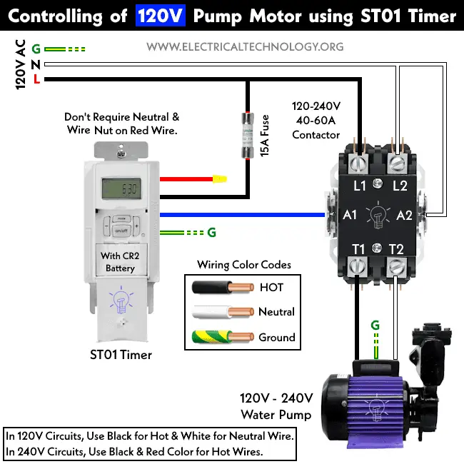
Crédito para Electricaltechnology
Contactors are essential in motor control applications, providing:
- Safe starting and stopping of electric motors
- Proteção contra sobrecarga when combined with thermal overload relays
- Remote operation from control panels or automation systems
- Emergency stop capability para conformidade com a segurança
Automação industrial
In manufacturing and process control:
- Conveyor system control
- Pump and compressor operation
- Equipamento de manuseamento de materiais
- Process line automation
Commercial Building Systems
- Controlo HVAC: Managing heating, ventilation, and air conditioning systems
- Lighting Management: Controlling large lighting installations in office buildings, retail spaces
- Distribuição de energia: Switching electrical panels and distribution boards
Produção e distribuição de energia
- Sistemas de controlo de geradores
- Capacitor bank switching for power factor correction
- Substation automation
- Sistemas de energia renovável (solar and wind power)
Contactor Specifications and Selection
Classificações eléctricas
- Tensão nominal: Maximum voltage the contactor can safely handle
- Classificação atual: Maximum continuous current capacity
- Horsepower Rating: Motor load capacity at specific voltages
- Categoria de utilização: Defines the type of load (AC-1 for resistive, AC-3 for motors)
Especificações da bobina
- Tensão da bobina: Operating voltage for the electromagnetic coil (24V, 120V, 240V, etc.)
- Coil Type: AC or DC operation
- Consumo de energia: Energy required to maintain coil energization
Caraterísticas mecânicas
- Contact Material: Silver alloy, silver oxide, or other specialized materials
- Número de postes: Single-pole, two-pole, three-pole, or four-pole configurations
- Contactos auxiliares: Additional contacts for control circuit functions
- Tipo de montagem: DIN rail, panel mount, or other installation methods
Considerações ambientais
- Gama de temperaturas: Operating temperature limits
- Enclosure Rating: Protection against dust, moisture, and environmental hazards
- Resistência à vibração: Ability to withstand mechanical stress
- Altitude Rating: Performance at various elevations
Instalação e cablagem
Typical Contactor Connections
- Line Terminals (L1, L2, L3): Connect to incoming power supply
- Load Terminals (T1, T2, T3): Connect to the electrical load (motor, lights, etc.)
- Coil Terminals (A1, A2): Connect to control circuit voltage
- Contactos auxiliares: Used for signaling, interlocking, or feedback circuits
Control Circuit Integration
Contactors are typically integrated into control systems with:
- Start/stop pushbuttons for manual operation
- Overload relays for motor protection
- PLC outputs for automated control
- Timer relays for sequenced operations
Considerações de segurança
- Ligação à terra correta of all metallic parts
- Arc flash protection when working on energized equipment
- Lockout/tagout procedures during maintenance
- Adequate clearances for safe operation and maintenance
Manutenção e resolução de problemas
Regular Maintenance Tasks
- Inspeção visual: Check for signs of overheating, corrosion, or physical damage
- Contact Examination: Inspect contacts for pitting, burning, or excessive wear
- Coil Testing: Verify proper coil resistance and insulation
- Funcionamento mecânico: Ensure smooth armature movement and proper spring action
Common Problems and Solutions
- Contacts Not Closing: Check coil voltage, mechanical obstructions, or worn springs
- Contacts Welded Shut: Usually indicates overcurrent conditions or inadequate arc suppression
- Chattering Operation: May indicate low coil voltage or mechanical issues
- Sobreaquecimento: Could result from poor connections, overloading, or inadequate ventilation
Replacement Guidelines
Replace contactors when:
- Contacts show excessive wear or damage
- Coil resistance is outside manufacturer specifications
- Mechanical operation becomes sluggish or irregular
- Arc suppression components are damaged
Tendências e Tecnologia Futuras
Contactores inteligentes
Modern contactors increasingly incorporate digital technology:
- Built-in diagnostics for predictive maintenance
- Communication capabilities for system integration
- Monitoramento de energia features
- Remote monitoring through IoT connectivity
Solid-State Alternatives
While electromechanical contactors remain dominant, solid-state switching devices offer:
- Faster switching speeds
- No mechanical wear
- Funcionamento silencioso
- Precise control capabilities
Conclusão
Understanding what a contactor is and how it functions is essential for anyone working with electrical systems. These reliable, electromagnetic switching devices provide safe, efficient control of high-power electrical loads across countless applications, from simple motor starters to complex industrial automation systems.
Whether you’re specifying equipment for a new installation, troubleshooting an existing system, or planning maintenance activities, a thorough understanding of contactor operation, types, and applications will help ensure safe, reliable electrical system performance.
The key to successful contactor application lies in proper selection based on load requirements, environmental conditions, and control system integration needs. With proper installation, maintenance, and operation, contactors provide years of reliable service in the demanding world of electrical power control.
Principais conclusões:
- A contactor is an electromagnetic switch designed for high-power electrical circuit control
- Contactors differ from relays primarily in their current-handling capacity and construction
- AC and DC contactors have different design features to handle their respective current types
- Proper selection, installation, and maintenance are crucial for safe, reliable operation
- Contactors are essential components in motor control, lighting systems, and industrial automation
Frequently Asked Questions About Contactors
What is the difference between a contactor and a relay?
The main differences are load capacity and construction. Contactors are designed for currents above 10 amperes and feature robust construction with arc suppression mechanisms. Relays typically handle currents of 10 amperes or less and are used for control circuits. Contactors also primarily use normally open contacts, while relays can have normally open, normally closed, or changeover contacts.
Why do contactors fail or burn out?
Common causes of contactor failure include:
– Overloading beyond rated capacity
– Contact welding from excessive arcing
– Coil overheating due to voltage fluctuations
– Environmental factors like dust, moisture, or corrosive gases
– Mechanical wear from excessive cycling
– Poor electrical connections causing voltage drops
How do you troubleshoot a contactor that’s not working?
Follow this systematic approach:
1. Check control voltage at coil terminals (A1, A2)
2. Test coil resistance with a multimeter
3. Inspect contacts for damage, pitting, or welding
4. Verify mechanical operation – listen for proper “clicking” sound
5. Check auxiliary contacts for continuity
6. Examine overload relay settings and operation
How do you wire a contactor for motor control?
Basic motor contactor wiring involves:
1. Power connections: Connect L1, L2, L3 to incoming power supply
2. Load connections: Connect T1, T2, T3 to motor terminals
3. Control circuit: Wire A1, A2 to control voltage (typically 24V, 120V, or 240V)
4. Start/stop buttons: Wire in series with coil circuit
5. Auxiliary contacts: Use for holding circuit and status indication
6. Overload relay: Connect in series for motor protection
What causes contactor chatter or buzzing?
Contactor chattering indicates:
– Low control voltage causing insufficient magnetic force
– Loose electrical connections creating voltage drops
– Damaged shading coil (in AC contactors)
– Mechanical obstructions preventing proper contact closure
– Voltage fluctuations in the supply system
– Worn contact surfaces creating poor connections
Can you use an AC contactor for DC applications?
Generally not recommended without modifications. AC contactors lack adequate arc suppression for DC applications since DC current doesn’t naturally zero-cross like AC. If absolutely necessary, the contactor must be significantly derated (typically to 50% or less of AC rating) and additional arc suppression must be added. It’s always better to use a DC-rated contactor for DC applications.
How do you test if a contactor is bad?
Key tests include:
1. Coil resistance test: Measure resistance across A1-A2 terminals
2. Contact continuity test: Check resistance across main contacts when energized (should be near zero ohms)
3. Insulation test: Verify no continuity between coil and contacts when de-energized
4. Mechanical operation test: Listen for proper clicking and observe contact movement
5. Voltage test: Measure actual coil voltage during operation
What are the different types of contactors?
Main contactor types include:
– AC Contactors: For alternating current applications (most common)
– DC Contactors: Designed for direct current loads
– Reversing Contactors: Allow motor direction reversal
– Lighting Contactors: Optimized for resistive lighting loads
– Capacitor Contactors: Designed for switching power factor correction capacitors
– Vacuum Contactors: For medium and high-voltage applications
Why won’t my contactor energize?
Common causes include:
– No control voltage at coil terminals
– Blown fuse in control circuit
– Open circuit in control wiring
– Faulty coil (burned out or damaged)
– Mechanical obstruction preventing armature movement
– Incorrect coil voltage rating for applied voltage
– Poor electrical connections causing voltage drops
How often should contactors be maintained?
Recommended maintenance schedule:
– Monthly: Visual inspection for damage, overheating, or contamination
– Quarterly: Clean contacts and check connections
– Annually: Comprehensive testing including coil resistance and contact condition
– As needed: Replace when contacts show excessive wear, pitting, or burning
– After fault conditions: Inspect immediately after any overload or short-circuit events
Can a contactor work without an overload relay?
Yes, but it’s not recommended for motor applications. While contactors can operate independently, overload relays provide essential motor protection against overcurrent conditions. For lighting or heating loads, overload protection may not be as critical, but motor applications should always include proper overload protection to prevent damage and ensure safety.
What voltage should I use for the contactor coil?
As tensões comuns da bobina incluem:
– 24V DC/AC: Most common in industrial control systems
– 120V AC: Standard in North American residential/commercial applications
– 240V AC: Used in higher voltage control systems
– 480V AC: Industrial applications with high voltage control
Choose coil voltage based on your available control power supply and safety requirements. Lower voltages (24V) are safer for operator interfaces.
Relacionadas
Como selecionar contactores e disjuntores com base na potência do motor
