Pada halaman ini
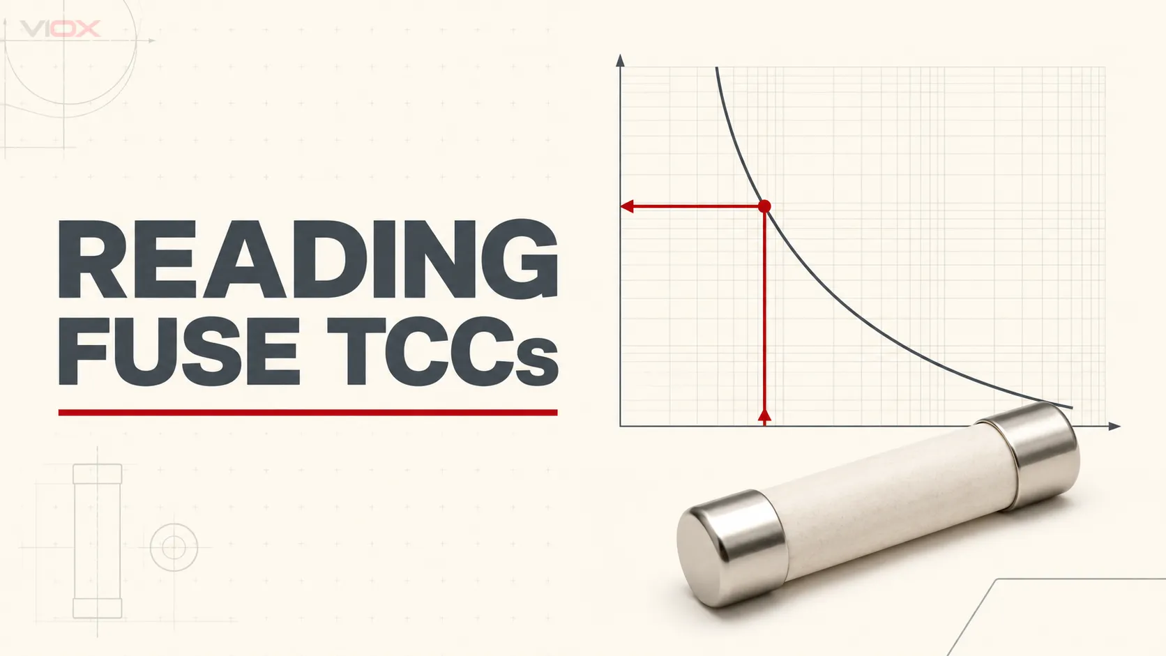
A keluk masa-arus fius (TCC) menunjukkan bagaimana masa kendalian berubah apabila arus lampau meningkat. Untuk membacanya, cari arus yang diperlukan pada paksi mendatar logaritma, bergerak secara menegak ke keluk bagi kadaran fius yang tepat, kemudian bergerak secara mendatar ke paksi menegak logaritma untuk membaca masa. Terbalikkan laluan tersebut apabila anda mengetahui masa yang diperlukan dan perlu mencari arus yang sepadan.
Kaedah pengesanan itu hanyalah separuh pertama daripada tugas tersebut. Sebelum menggunakan hasilnya, kenal pasti sama ada helaian tersebut menunjukkan lebur minimum (pra-arka), lebur purata, atau pembersihan jumlah. Garis lebur purata nominal bukanlah had pembersihan yang dijamin, dan TCC tidak menggantikan kadaran voltan, keupayaan pemutusan, I²t, arus puncak yang dibenarkan, atau data penyelarasan pengilang bagi fius tersebut.
Enam Perkara untuk Dikenal Pasti Sebelum Membaca Keluk
Jangan bermula pada paksi. Bermula dengan blok tajuk dokumen dan petunjuk.
| Semak | Perkara yang perlu direkodkan | Berhenti jika |
|---|---|---|
| Keluarga fius | Pengilang dan siri atau kelas yang tepat | Lengkung tersebut tergolong dalam siri yang berbeza |
| Kadar fius | Lengkung atau jalur ampere yang khusus | Penarafan yang diperlukan tiada dan interpolasi tidak dibenarkan |
| Jenis lengkung | Peleburan minimum, peleburan purata, atau pembersihan jumlah | Jenis lengkung tidak dinyatakan atau tidak dapat disahkan |
| Asas arus | Ampere, kiloampere, atau gandaan arus terkadar In | Unit paksi tidak jelas |
| Asas masa | Saat, kitaran, atau unit lain yang diisytiharkan | Anda tidak boleh menukar keperluan projek kepada unit yang diplotkan |
| Syarat dan nota | Asas AC/DC, voltan ujian, andaian ambien, pemuatan awal, toleransi, frekuensi, atau nota pengilang lain | Sistem yang dimaksudkan berada di luar syarat yang diterbitkan |
Lengkung yang diambil daripada fius yang kelihatan serupa bukanlah pengganti. Dua pautan fius dengan arus berkadar yang sama boleh mempunyai kategori penggunaan, reka bentuk elemen, kelakuan masa-arus, dan prestasi pelepasan yang berbeza. The panduan terminologi pautan fius VIOX menjelaskan mengapa pautan fius yang boleh diganti dan sistem fius lengkap mesti juga ditentukan secara berasingan.
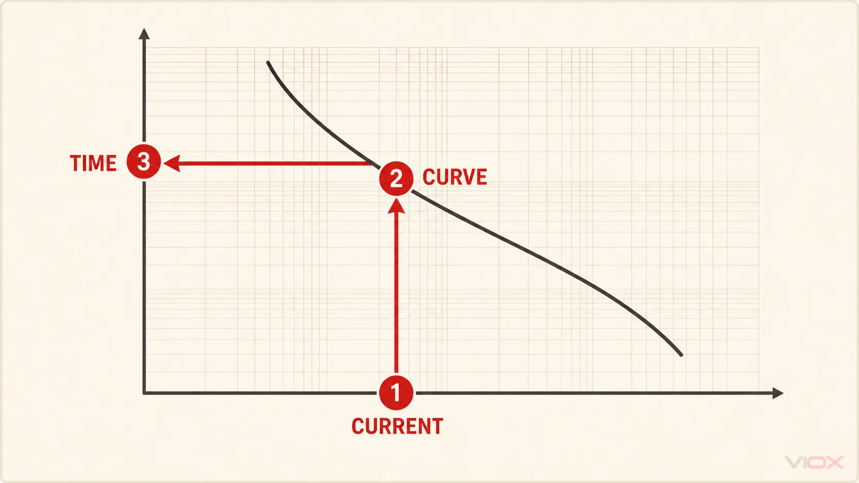
Cara Membaca Arus-ke-Masa dalam Lima Langkah
Gunakan urutan ini apabila soalan reka bentuk adalah:
Pada arus yang dinyatakan, berapakah anggaran masa yang diambil oleh fius ini untuk cair atau terputus?
Langkah 1: Pilih lengkung yang tepat
Cari garisan atau jalur yang dilabelkan untuk kadaran ampere yang diperlukan dalam keluarga fius yang betul. Satu helaian mungkin menunjukkan banyak kadaran bersama-sama. Lengkung yang jaraknya rapat mudah dikelirukan, terutamanya pada carta logaritma.
Hasil yang dijangkakan: satu lengkung atau jalur yang dikenal pasti yang terikat pada keluarga bahagian pengilang yang didokumenkan dan kadaran ampere.
Keadaan berhenti: jangan anggarkan lengkung yang hilang antara kadaran bersebelahan melainkan pengilang membenarkan kaedah tersebut secara eksplisit atau membekalkan data perantaraan.
Langkah 2: Cari arus pada paksi mendatar
Baca label paksi dengan teliti. Paksi-x mungkin menunjukkan:
- arus sebenar dalam ampere;
- arus prospektif dalam kiloampere; atau
- arus sebagai gandaan arus berkadar, seperti 2 × In atau 10 × In.
Jika paksi menggunakan gandaan, kirakan gandaan tersebut sebelum memasukkan carta:
Gandaan arus = arus yang digunakan / arus terkadar fiusBagi fius 20 A yang membawa 100 A, arus yang digunakan ialah 5 × In. Pengiraan ini mengenal pasti satu titik pada paksi; ia tidak meramalkan masa kendalian tanpa lengkung yang betul.
Hasil yang dijangkakan: satu nilai arus yang dinyatakan dalam unit yang sama seperti carta.
Keadaan berhenti: jangan anggap ampere dan gandaan In sebagai boleh tukar ganti.
Langkah 3: Bergerak secara menegak ke lengkung atau jalur
Daripada arus yang dipilih, surih satu garisan menegak ke atas sehingga ia bertemu dengan lengkung fius yang betul.
Jika graf menunjukkan satu garisan lebur purata, persilangan tersebut memberikan nilai nominal. Jika ia menunjukkan jalur atau sempadan lebur minimum dan pembersihan total yang berasingan, rekodkan kedua-dua persilangan tersebut.
Hasil yang dijangkakan: satu persilangan untuk garisan nominal, atau dua persilangan untuk julat masa.
Keadaan berhenti: jika garisan menegak melintasi beberapa kadaran fius, sahkan semula petunjuk sebelum meneruskan.
Langkah 4: Gerak secara mendatar ke paksi masa
Dari titik persilangan, surih secara mendatar ke paksi-y. Baca masa menggunakan pembahagian logaritma.
Satu titik di pertengahan antara 1 saat dan 10 saat bukanlah 5.5 saat. Pada skala logaritma asas-10, titik tengah geometri adalah lebih kurang 3.16 saat. Gunakan pembahagian grid kecil yang dibekalkan pada helaian sebenar dan bukannya interpolasi visual linear.
Hasil yang dijangkakan: masa nominal atau julat masa terhad, dengan jenis lengkung ditulis di sebelahnya.
Langkah 5: Rekodkan keputusan berserta penentunya
Nota kejuruteraan yang berguna kelihatan seperti ini:
Fius: [pengilang, siri, kadaran]
Arus yang digunakan: [A atau gandaan In]
Jenis lengkung: [lebur minimum / lebur purata / pembersihan jumlah]
Keputusan bacaan: [masa atau julat]
Dokumen: [nombor helaian data dan semakan]
Syarat/had: [nota berkaitan]
Jangan hanya merekodkan “fius terbuka dalam 0.2 s.” Tanpa jenis lengkung dan sumber, pembaca lain tidak dapat mengetahui sama ada 0.2 s itu adalah peleburan minimum, peleburan nominal, atau jumlah pembersihan maksimum.
Cara Membaca Masa-ke-Arus
Kadangkala keperluan reka bentuk adalah sebaliknya:
Apakah arus yang diperlukan untuk fius ini beroperasi dalam masa sasaran?
Mulakan pada masa yang diperlukan pada paksi menegak, bergerak secara mendatar ke lengkung atau jalur yang dipilih, kemudian bergerak secara menegak ke bawah ke paksi arus.
Arah ini berguna apabila menyemak:
- sama ada arus kerosakan yang diketahui mencapai rantau masa operasi yang diperlukan;
- sama ada denyut arus masuk yang singkat memasuki rantau peleburan fius;
- yang mana kadaran yang diterbitkan dalam satu keluarga fius adalah paling hampir dengan keperluan masa-arus yang ditetapkan.
Jawapannya masih terikat pada jenis lengkung yang diterbitkan. Arus yang dibaca daripada garisan lebur purata tidak membuktikan pemutusan maksimum dalam masa tersebut.
Contoh Kerja: Membaca Lengkung Mersen AJT30 yang Diterbitkan
Satu halaman Mersen Cara Membaca Keluk Masa-Arus menggunakan keluarga Kelas J tunda masa AJT. Helaian tersebut dilabelkan data masa-arus lebur, dan Mersen menyifatkan lengkung selanjarnya sebagai masa lebur purata nominal.
Bagi yang diterbitkan AJT30 lengkung:
- Masuk ke paksi-x pada 160 A.
- Gerak secara menegak ke 30 A lengkung.
- Gerak secara mendatar ke paksi masa.
- Bacaan yang diterbitkan ialah 10 saat.
Membaca dalam arah bertentangan:
- Masukkan paksi-y pada 0.1 saat.
- Gerakkan secara mendatar ke 30 A lengkung.
- Gerakkan ke bawah ke paksi arus.
- Bacaan yang diterbitkan ialah 320 A.
| Soalan | Laluan lengkung yang diterbitkan | Hasil pada contoh Mersen |
|---|---|---|
| Berapa lama pada 160 A? | 160 A → lengkung AJT30 → paksi masa | 10 s |
| Berapakah arus untuk 0.1 s? | 0.1 s → lengkung AJT30 → paksi arus | 320 A |
Nilai-nilai ini menggambarkan cara membaca lengkung pengilang yang dinamakan itu. Nilai-nilai ini bukan nilai sejagat untuk setiap fius 30 A, dan ia mewakili ciri pelakuran purata yang diterbitkan—bukan jaminan menyeluruh bahawa setiap AJT30 akan memutuskan litar sepenuhnya tepat pada masa tersebut. Penarafan voltan, penarafan pemutusan, aplikasi, dan data pengilang yang lain masih menentukan pilihan akhir.
Peleburan Minimum, Peleburan Purata, dan Pembersihan Keseluruhan Adalah Berbeza
Label di sekeliling lengkung menentukan maksud nombor tersebut.
| Lengkung atau istilah | Apa yang diwakilinya | Penggunaan yang sesuai | Apa yang tidak dibuktikan olehnya |
|---|---|---|---|
| Peleburan minimum / pra-arka minimum | Masa paling awal elemen fius mungkin melebur pada arus yang dinyatakan | Pemeriksaan sempadan koordinasi dan 'ride-through' | Masa gangguan akhir |
| Pelakuran purata | Kelakuan pelakuran elemen nominal atau tipikal | Perbandingan umum dan kelakuan anggaran | Minimum atau maksimum yang dijamin |
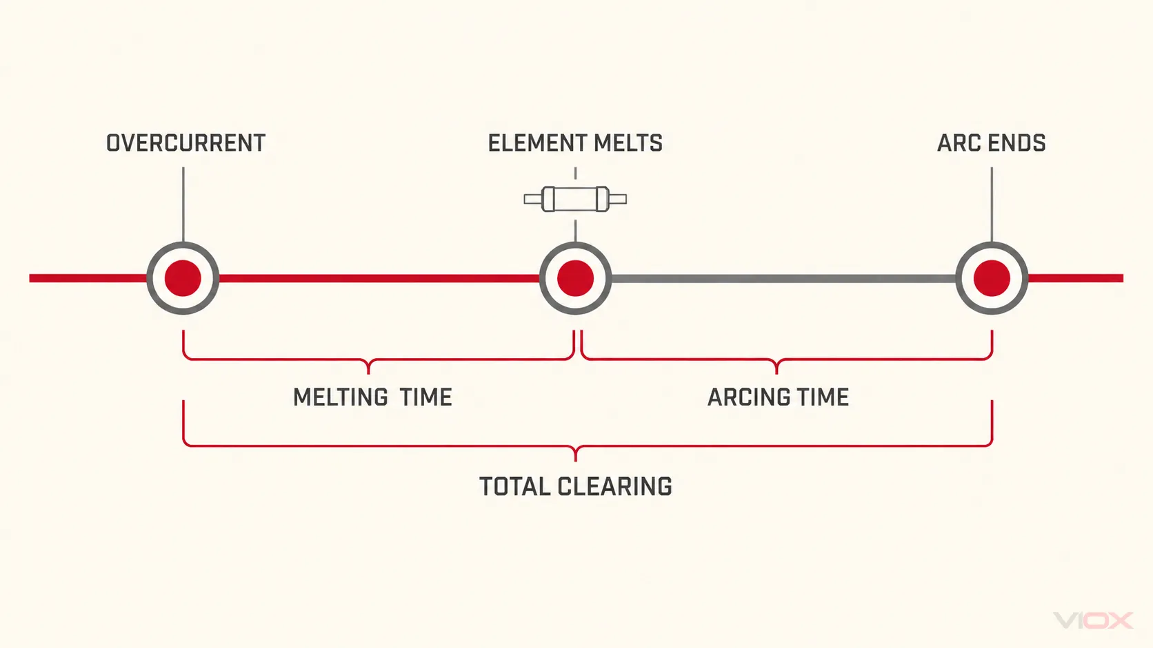
| Masa arka | Masa dari pelakuran elemen sehingga arus diputuskan | Memahami jurang antara pelakuran dan pembersihan | Tindak balas keseluruhan daripada permulaan kerosakan |
| Pembersihan keseluruhan | Masa lebur ditambah masa arka | Sempadan pembersihan maksimum apabila diterbitkan sedemikian | Perlindungan peralatan tanpa menyemak data let-through dan tahanan |
| Jalur toleransi | Julat yang dibatasi oleh lengkung minimum dan maksimum yang berkaitan | Interpretasi julat masa yang konservatif | Satu masa kendalian tepat yang tunggal |
Eaton mentakrifkan masa pembersihan sebagai jumlah selang masa dari permulaan arus lebih sehingga gangguan litar terakhir, yang terdiri daripada masa lebur ditambah masa arka. Panduan penyelarasan selektif Mersen juga membezakan lengkung lebur minimum dan pembersihan jumlah serta menggunakan sempadan tersebut—bukan garisan purata—untuk menilai pemisahan antara peranti.
Terminologi boleh berbeza mengikut wilayah dan pengilang. “Pre-arcing” biasanya digunakan untuk tempoh sebelum elemen melebur; sesetengah literatur menggunakan “masa lebur.” Baca definisi yang dicetak dalam sumber data yang tepat dan bukannya menganggap setiap katalog menggunakan label yang sama.
Mengapa Kedua-dua Paksi Adalah Logaritma
Kelakuan fius merangkumi julat arus dan masa yang luas. Satu carta mungkin perlu memaparkan kelakuan beban lampau tempoh panjang dan kelakuan arus tinggi sub-kitaran. Paksi logaritma memampatkan dekad tersebut ke dalam graf yang boleh dibaca.
Pada paksi asas-10:
| Selang utama | Nilai kecil tipikal |
|---|---|
| 1 hingga 10 | 2, 3, 4, 5, 6, 7, 8, 9 |
| 10 hingga 100 | 20, 30, 40, 50, 60, 70, 80, 90 |
| 0.01 hingga 0.1 | 0.02, 0.03, 0.04, 0.05, dan seterusnya |
Jarak visual antara 10 dan 20 tidak sama dengan jarak antara 20 dan 30. Apabila resolusi carta tidak mencukupi untuk membuat keputusan, dapatkan data digital pengilang, perisian penyelarasan, atau lengkung yang lebih jelas daripada meneka berdasarkan imej yang kecil.
Menukar Bacaan Lengkung kepada Pemeriksaan Kejuruteraan
Bacaan masa-arus hanya menjadi berguna apabila dibandingkan dengan keperluan litar. Tiga profil biasanya penting.
1. Profil beban normal dan arus masuk (inrush)
Plot atau perihalkan magnitud dan tempoh arus permulaan, pemagnetan, pengecasan, atau arus transien lain yang dijangkakan. Sahkan bahawa profil tersebut kekal di luar sempadan lebur pengilang dengan margin reka bentuk dan keadaan operasi yang diperlukan.
Jangan selesaikan operasi gangguan hanya dengan meningkatkan kadaran ampere. Perubahan itu boleh melemahkan perlindungan konduktor atau peralatan. Periksa keluarga fius, kelakuan lengah masa, keadaan persekitaran, had terma pemegang, dan bentuk gelombang arus masuk (inrush) yang sebenar.
2. Had konduktor atau peralatan yang dilindungi
Bandingkan sempadan pemutusan fius dengan maklumat ketahanan konduktor atau peralatan yang berkenaan. Fius harus memutuskan arus lebih yang merosakkan sebelum had terma atau had kerosakan yang dibenarkan bagi item yang dilindungi itu dilampaui.
TCC generik tidak dapat menentukan perkara ini dengan sendirinya. Had yang diperlukan mestilah datang daripada kaedah reka bentuk, data peralatan, atau pihak berkuasa yang berkenaan bagi pasaran sasaran.
3. Perlindungan hulu dan hilir
Bagi dua fius yang disambung secara siri, pemeriksaan lengkung konvensional menggunakan sempadan pemutusan jumlah peranti hilir dan sempadan peleburan minimum peranti hulu. Di mana lengkung pemutusan jumlah hilir kekal terpisah daripada lengkung peleburan minimum hulu sepanjang julat yang dinilai, fius hilir dijangka beroperasi terlebih dahulu dalam julat yang diplotkan itu.
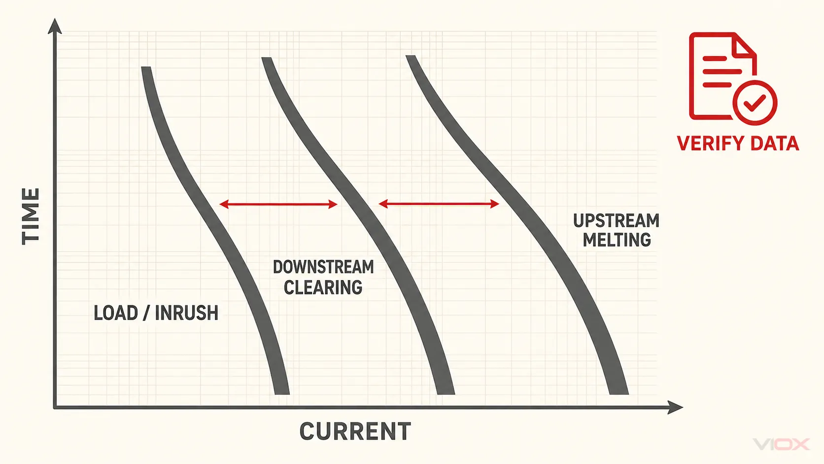
Ini merupakan peraturan saringan, bukan sijil penyelarasan sejagat. Mersen menyatakan bahawa analisis TCC konvensional mungkin tidak mewakili pemilihan dengan tepat apabila peranti pengehad arus dan operasi pemutus serta-merta terlibat. Jadual pemilihan pengeluar, kombinasi yang diuji, data arus puncak, data I²t, atau kajian perlindungan rasmi mungkin diperlukan.
Untuk perbandingan teknologi yang berasingan, gunakan VIOX’s panduan masa tindak balas fius lwn MCB. Untuk lengkung pelindung B/C/D dan pelindung elektronik, gunakan panduan lengkung pelindung pemutus litar.
Di mana I²t Sesuai—dan Di mana TCC Berhenti
TCC menghubungkan magnitud arus dengan masa. I²t menerangkan kamiran kuasa dua arus sepanjang masa:
I²t = ∫ i²(t) dtOleh kerana arus kerosakan berubah semasa gangguan, kamiran adalah lebih tepat berbanding mendarabkan satu arus malar yang diandaikan dengan satu nilai masa.
Data fius mungkin membezakan:
- I²t lebur atau pra-arka: kamiran tenaga sehingga elemen lebur;
- I²t arka: kamiran tenaga semasa arka;
- I²t pemutusan jumlah: kamiran gabungan sehingga gangguan akhir.
Gunakan definisi pengilang dan syarat ujian yang tepat. Panduan teknologi fius Eaton menekankan bahawa perbandingan I²t denyut dan I²t lebur fius mesti mengambil kira bentuk gelombang aplikasi dan panduan produk. Littelfuse juga memisahkan lengkung masa-arus daripada lengkung puncak arus lepas: yang kedua menangani arus puncak sebenar yang dilalui semasa gangguan pengehadan arus.
TCC sahaja tidak mencukupi apabila keputusan bergantung pada:
- ketahanan semikonduktor atau elektronik kuasa;
- arus litar pintas prospektif yang tinggi dalam kawasan pengehadan arus;
- tegasan elektromekanikal puncak;
- pemasangan bertingkat, perlindungan sandaran, atau gabungan selektif yang diuji;
- sistem campuran fius-dan-pemutus litar yang memasuki kawasan serta-merta pemutus litar;
- pematuhan dengan keperluan selektiviti khusus projek.
Dalam kes tersebut, dapatkan jadual I²t pengeluar, carta arus puncak (peak let-through), jadual selektiviti, lengkung peranti yang tepat, dan sebarang data kajian yang diperlukan.
Ralat Bacaan Biasa dan Tindakan Pembetulan
| ralat | Mengapa ia gagal | Tindakan pembetulan |
|---|---|---|
| Membaca kadaran fius terdekat dan bukannya yang tepat | Kadaran bersebelahan boleh mempunyai lengkung yang berbeza secara material | Dapatkan lengkung kadaran yang tepat |
| Menganggap garisan purata sebagai had yang dijamin | Peleburan purata tidak termasuk toleransi dan mungkin tidak termasuk masa arka | Gunakan sempadan lebur minimum dan pembersihan jumlah |
| Membaca paksi log sebagai linear | Titik anggaran boleh menjadi jauh daripada nilai yang diterbitkan | Ikuti subbahagian logaritma yang dilabelkan |
| Mengabaikan ampere berbanding gandaan In | Titik paksi-x menjadi salah sebelum lengkung dibaca | Tukarkan unit secara eksplisit |
| Mengandaikan “terbuka” sentiasa bermaksud pembersihan jumlah | Terminologi pengilang dan label lengkung adalah berbeza | Rekodkan istilah tepat dokumen tersebut |
| Membandingkan lengkung daripada asas ujian yang tidak berkaitan | Pemisahan ketara mungkin tidak mewakili keadaan yang sama | Gunakan data pengilang/projek yang serasi |
| Menggunakan TCC sahaja dalam kawasan pengehadan arus | Arus puncak dan tenaga mungkin menentukan hasil | Semak data I²t, arus puncak yang dilepaskan, dan selektiviti |
| Memilih hanya berdasarkan kadaran ampere | Voltan, keupayaan pemutusan, kelas, pemegang, dan aplikasi masih belum diselesaikan | Lengkapkan spesifikasi fius penuh |
Lembaran Kerja Bacaan TCC Fius
Salin jadual ini ke dalam rekod reka bentuk atau semakan perolehan.
| Bidang | Entri projek |
|---|---|
| Pengeluar | |
| Keluarga / siri fius | |
| Nombor katalog | |
| Nilai semasa | |
| Voltan terkadar dan asas AC/DC | |
| Kadar pemutusan / gangguan | |
| Dokumen lengkung dan semakan | |
| Jenis lengkung | |
| Unit paksi mendatar | |
| Unit paksi menegak | |
| Arus yang digunakan atau masa yang diperlukan | |
| Baca nilai atau julat masa pelakuran | |
| Baca nilai atau julat pembersihan jumlah | |
| Profil beban/arus masuk diperiksa | Ya / Tidak |
| Had peralatan atau konduktor yang dilindungi telah diperiksa | Ya / Tidak |
| Penyelarasan hulu/hilir telah diperiksa | Ya / Tidak |
| Data I²t diperlukan dan telah diperiksa | Ya / Tidak / Tidak berkenaan |
| Data puncak arus lalu (peak let-through) diperlukan dan telah diperiksa | Ya / Tidak / Tidak berkenaan |
| Jadual atau kajian selektiviti pengeluar diperlukan | Ya / Tidak / Tidak berkenaan |
| Andaian dan perkara yang belum selesai |
Spesifikasi fius yang lengkap juga memerlukan kategori penggunaan atau kelas fius, format fizikal, keserasian pemegang, dan keadaan aplikasi yang betul. Mulakan dengan panduan fius elektrik VIOX untuk konteks peranti dan pemilihan yang lebih luas; gunakan panduan pemilihan fius IEC 60269 untuk kelas IEC dan sempadan sistem; kemudian gunakan halaman produk fius VIOX sebagai laluan komersial untuk penilaian keluarga produk.
Pengesahan Akhir Sebelum Anda Meluluskan Fius
Hasil TCC yang boleh dipertahankan harus menjawab kesemua lima soalan:
- Adakah ini keluarga pengilang dan kadaran ampere yang tepat?
- Adakah keputusan tersebut menyatakan peleburan minimum, peleburan purata, atau pembersihan jumlah?
- Adakah skala logaritma dibaca dalam unit yang betul?
- Adakah fius tersebut mampu menahan profil beban yang disasarkan dan terputus sebelum had kerosakan yang berkenaan?
- Adakah I²t, arus puncak yang dibenarkan lalu, jadual pemilihan, dan kadaran lain telah disemak di mana TCC sahaja tidak mencukupi?
Jika sebarang jawapan tidak pasti, kekalkan pemilihan sebagai sementara. Untuk pertanyaan produk yang boleh disemak, hantarkan voltan sistem, tugas AC/DC, arus normal, profil arus masuk, arus kerosakan prospektif, kelas fius, masa operasi yang diperlukan, format pemegang, dan keperluan penyelarasan kepada [email protected].
Sumber
- IEC 60269-1:2024 — Fius voltan rendah, Bahagian 1: Keperluan am
- Mersen — Cara Membaca Lengkung Masa-Arus
- Mersen — Menilai Penyelarasan Selektif Antara Fius Pengehad Arus dan Pemutus Litar Bukan Pengehad Arus
- Eaton — Teknologi Fius: Terminologi, Spesifikasi dan Pemilihan Peranti
- Littelfuse — Panduan Pemilihan Fuseology
- Littelfuse — Asas Fius