Pada halaman ini
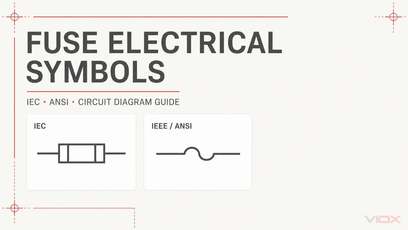
A simbol elektrik fius mengenal pasti fius atau fungsi perlindungan berkaitan fius dalam gambar rajah litar. Simbol asas diletakkan secara bersiri dengan pengalir, tetapi bentuk tepatnya mungkin berbeza antara sistem lukisan IEC dan ANSI/IEEE. Simbol itu sendiri biasanya tidak tidak memberitahu anda kadaran arus, kadaran voltan, keupayaan pemutusan, kesesuaian AC/DC atau ciri masa-arus fius tersebut. Butiran tersebut mesti diperoleh daripada anotasi berdekatan, jadual lukisan, helaian data fius atau dokumentasi peralatan.
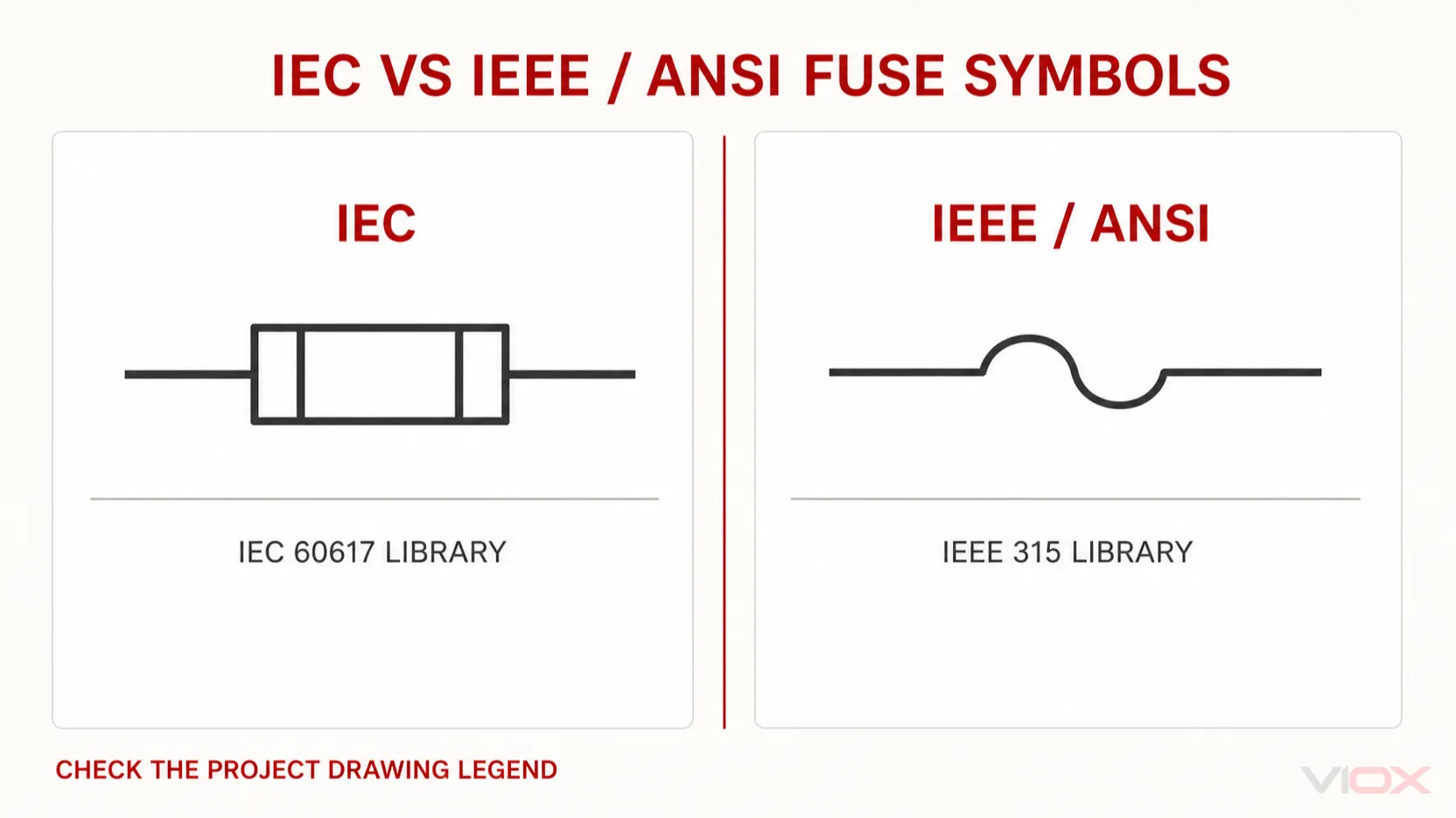
Rujukan Pantas Simbol Elektrik Fius
IEC 60617 mengandungi lebih daripada satu simbol fius kerana sesuatu lukisan mungkin perlu menunjukkan fius asas, mekanisme penyerang, sesentuh penggera, atau fungsi pensuisan dan pengasingan gabungan. Jadual di bawah memisahkan fungsi-fungsi ini dan bukannya menganggap setiap segi empat tepat dalam skema sebagai peranti yang sama.
| Fungsi lukisan | Apa yang disampaikan oleh simbol tersebut | Apa yang tidak dibuktikan olehnya |
|---|---|---|
| Fius am | Fius atau pautan fius yang boleh diganti disambungkan dalam laluan arus | Arus, voltan, kategori penggunaan, kapasiti pemutusan, atau kadaran AC/DC |
| Fius dengan pengetuk (striker) | Kendalian fius boleh melepaskan pengetuk mekanikal | Apa yang diputuskan atau diisyaratkan oleh pengetuk tersebut melainkan ditunjukkan sebaliknya dalam rajah |
| Fius dengan sesentuh penggera | Operasi fius dikaitkan dengan sesentuh isyarat | Kadaran voltan/arus sesentuh atau logik penggera hiliran |
| Fius dengan penggera berasingan | Litar fius dan penggera ditunjukkan sebagai fungsi yang berkaitan tetapi berasingan dari segi elektrik | Modul penggera atau susunan pendawaian yang tepat |
| Fius-suis | Perlindungan fius digabungkan dengan fungsi pensuisan | Kesesuaian untuk pensuisan beban tanpa mengesahkan kadaran peranti |
| Pemutus fius / pengasing fius | Perlindungan fius digabungkan dengan fungsi pemutusan atau pengasingan | Bahawa peranti tersebut boleh memutuskan arus beban |
| Fius suis-pemutus (fuse switch-disconnector) | Fungsi perlindungan fius, pensuisan beban, dan pengasingan digabungkan | Kategori penggunaan atau had operasi yang berkenaan |
| Fius terma / pemutus terma | Peranti tidak boleh set semula yang terbuka disebabkan oleh suhu yang berlebihan | Perlindungan arus lebih konvensional atau kebolehgantian di bawah semua keadaan |
Perbezaan ini penting dalam lukisan panel. A fius, suis fius, pemutus fius, dan suis-pemutus fius (fuse switch-disconnector) bukanlah nama yang boleh ditukar ganti. Simbolnya menggambarkan fungsi yang berbeza, dan peranti yang dipasang mestilah mempunyai kadaran yang menyokong operasi yang dimaksudkan. Untuk perbezaan praktikal penukaran beban, lihat Pemegang Fius lwn Pemutus Suis Fius.
Simbol Fius IEC lwn Simbol Fius ANSI/IEEE
Dua sistem simbol utama yang ditemui dalam dokumentasi elektrik antarabangsa ialah IEC 60617 dan IEEE/ANSI 315.
| Titik perbandingan | Lukisan IEC | Lukisan ANSI/IEEE |
|---|---|---|
| Rujukan utama | Pangkalan data simbol grafik IEC 60617 | IEEE/ANSI 315 |
| Konvensyen visual lazim | Elemen fius segi empat tepat yang padat dimasukkan ke dalam konduktor | Perwakilan fius yang melengkung, berbentuk S, atau yang ditetapkan mungkin muncul, terutamanya dalam lukisan Amerika Utara |
| Pasaran umum | Projek antarabangsa, Eropah, dan banyak pasaran Asia | Dokumentasi perindustrian Amerika Utara dan legasi |
| Orientasi | Boleh dilukis secara mendatar atau menegak | Boleh juga diputar untuk disesuaikan dengan arah litar |
| Kaedah tafsiran yang betul | Semak pustaka IEC yang digunakan oleh lukisan tersebut dan baca petunjuknya | Semak pustaka ANSI/IEEE dan petunjuk lukisan |
Pangkalan data rasmi IEC 60617 menyenaraikan simbol fius am dan entri tambahan untuk fius, fius penyerang (striker fuse), fius dengan sesentuh penggera, fius dengan penggera berasingan, suis fius, pemutus fius, dan suis-pemutus fius. IEEE/ANSI 315 menyediakan rangka kerja simbol grafik Amerika Utara.
Jangan kenal pasti piawaian berdasarkan satu bentuk sahaja. Pakej CAD mungkin menggunakan varian yang diluluskan berbeza, loji lama mungkin mengekalkan pustaka legasi, dan syarikat sering mengekalkan petunjuk lukisan mereka sendiri. Oleh itu, petunjuk pada set lukisan adalah pihak berkuasa serta-merta untuk projek tersebut.
Cara Membaca Maklumat di Sekitar Simbol Fius
Simbol grafik hanya menjawab soalan pertama: apakah fungsi yang terletak di sini? Teks di sekelilingnya mengenal pasti komponen dan prestasi yang diperlukan.
Pertimbangkan anotasi ilustrasi seperti:
F1 – 32 A gG, 500 V AC
| Anotasi | Maknanya |
|---|---|
F1 |
Penunjukan rujukan yang digunakan untuk mencari peranti yang sama dalam jadual, senarai pendawaian, susun atur panel, dan bil bahan |
32 A |
Penarafan arus fius yang ditetapkan untuk komponen yang didokumenkan |
gG |
Kategori penggunaan IEC untuk pautan fius julat penuh tujuan am |
500 V AC |
Jenis voltan dan arus yang dinyatakan untuk fius yang dipilih itu |
F1, F2, dan pengecam yang serupa adalah amalan penggubalan yang biasa, tetapi konvensyen penetapan rujukan boleh berbeza mengikut organisasi dan projek. Jangan sekali-kali menganggap bahawa huruf di sebelah simbol adalah spesifikasi yang lengkap.
Parameter penting mungkin ditunjukkan di sebelah simbol, dalam jadual fius, atau hanya dalam senarai komponen yang diluluskan:
- arus terkadar;
- voltan terkadar dan kesesuaian AC/DC;
- keupayaan pemutusan berkadar;
- kategori penggunaan, seperti gG, aM, gPV, atau kelas lain yang berkenaan;
- ciri masa-arus;
- sistem fius fizikal dan saiz;
- keperluan penyelarasan;
- pengilang dan nombor bahagian.
Untuk pemilihan fius voltan rendah industri, gunakan Panduan Fius IEC 60269 daripada cuba memilih fius berdasarkan simbol skematiknya.
Adakah Fius DC Mempunyai Simbol yang Berbeza?
Biasanya, simbol fius asas itu sendiri tidak membuktikan bahawa fius tersebut sesuai untuk DC.. Lukisan mungkin mengenal pasti litar DC melalui simbol bekalan, tajuk litar, tanda kekutuban, label pengalir, atau teks di sebelah fius. Fius yang dipilih mestilah mempunyai kadaran voltan DC dan keupayaan pemutusan yang sesuai untuk aplikasi tersebut.
Ini adalah perbezaan keselamatan yang kritikal. Arka DC tidak mendapat manfaat daripada lintasan sifar arus berkala yang terdapat dalam sistem AC, jadi fius yang boleh diterima dalam litar AC tidak boleh dianggap secara automatik sesuai pada voltan DC berangka yang sama.
Apabila membaca skema DC, sahkan semua perkara berikut:
- Voltan dan kekutuban litar.
- Kadaran voltan DC fius tersebut.
- Arus kerosakan prospektif yang tersedia.
- Keupayaan pemutusan DC yang diperlukan.
- Kategori penggunaan fius dan aplikasi yang dimaksudkan.
- Sebarang sekatan pengilang mengenai pemasangan atau gandingan pemegang fius.
The Panduan Fius AC lwn Fius DC menjelaskan mengapa badan fius yang kelihatan serupa mungkin mempunyai keupayaan pemutusan yang berbeza.
Simbol Fius Bertindak Pantas, Lengah Masa dan Terma
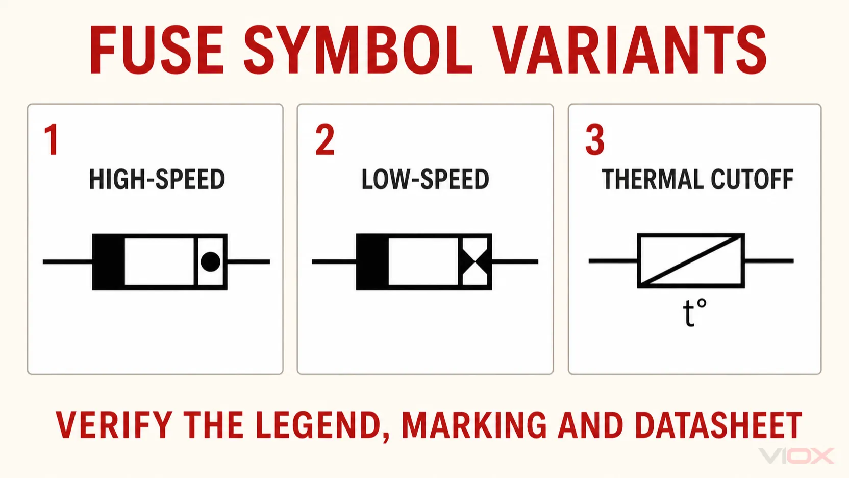
Fius Bertindak Pantas dan Fius Lengah Masa
Jangan menganggap bahawa setiap fius tindakan pantas atau lengah masa mempunyai bentuk skematik universal yang unik. Dalam banyak lukisan, simbol fius umum yang sama digunakan dan ciri pengendalian disampaikan melalui anotasi, jadual komponen, atau nombor bahagian.
Huruf seperti F dan T sering ditemui pada pautan fius kecil dan mungkin juga diulang dalam dokumentasi untuk menunjukkan ciri pengendalian. Ia tidak boleh dikelirukan dengan kategori penggunaan IEC 60269 seperti gG, pagi, atau gPV. Fius kecil diliputi oleh siri IEC 60127, manakala fius kuasa voltan rendah diliputi oleh IEC 60269.
Oleh itu, nota seperti T2A 250V pada fius kecil dan 32 A gG 500 V Bagi fius industri, terangkan sistem pengelasan yang berbeza. Kedua-duanya tidak boleh ditafsirkan berdasarkan bentuk simbol semata-mata.
Fius Terma atau Pemutus Terma
Fius terma bertindak balas terutamanya terhadap suhu pada peranti, bukan sekadar arus yang melebihi nilai terkadar. Ia biasanya merupakan peranti perlindungan sekali guna: sebaik sahaja elemen termanya beroperasi, peranti tersebut mesti diganti selepas punca pemanasan melampau diperbetulkan.
Simbol fius terma mungkin menggabungkan elemen seperti fius dengan penunjuk suhu atau dikenal pasti melalui maklumat suhu berdekatan. Oleh kerana pelaksanaan simbol berbeza-beza, semak legenda lukisan dan jadual komponen sebelum membezakan pemutus terma daripada suis terma atau peranti beban lampau.
Simbol Fius, Pemegang Fius dan Suis-Fius Adalah Berbeza
Pemegang fius menyokong dan menyambungkan pautan fius secara mekanikal, tetapi banyak skema hanya menunjukkan fungsi elektrik fius tersebut. Pemegang mungkin muncul dalam susun atur panel atau bil bahan tanpa menerima simbol berasingan dalam skema litar.
Jangan tafsirkan simbol fius umum sebagai bukti bahawa pemasangan boleh dibuka di bawah beban. Pemegang fius standard bukan secara automatik merupakan suis pemutus beban. Begitu juga, pemutus-fius menyediakan fungsi pengasingan, tetapi keupayaannya untuk menyambung atau memutuskan arus beban bergantung pada pengelasan dan kadaran peranti yang lengkap.
| Peranti ditunjukkan | Fungsi perlindungan | Fungsi pengasingan | Fungsi pensuisan beban |
|---|---|---|---|
| Pautan fius dalam pemegang fius | Ya, mengikut kadaran fius | Tidak ditentukan oleh simbol fius sahaja | Tidak ditentukan |
| Pemutus fius | Perlindungan fius | Ya, tertakluk kepada reka bentuk dan aplikasi peranti | Tidak ditetapkan secara automatik |
| Fius-suis | Perlindungan fius | Bergantung kepada klasifikasi peranti yang lengkap | Fungsi pensuisan diwakili, tetapi kadaran mesti diperiksa |
| Fius suis-pemutus (fuse switch-disconnector) | Perlindungan fius | Ya | Ya, dalam kategori penggunaan berkadarnya |
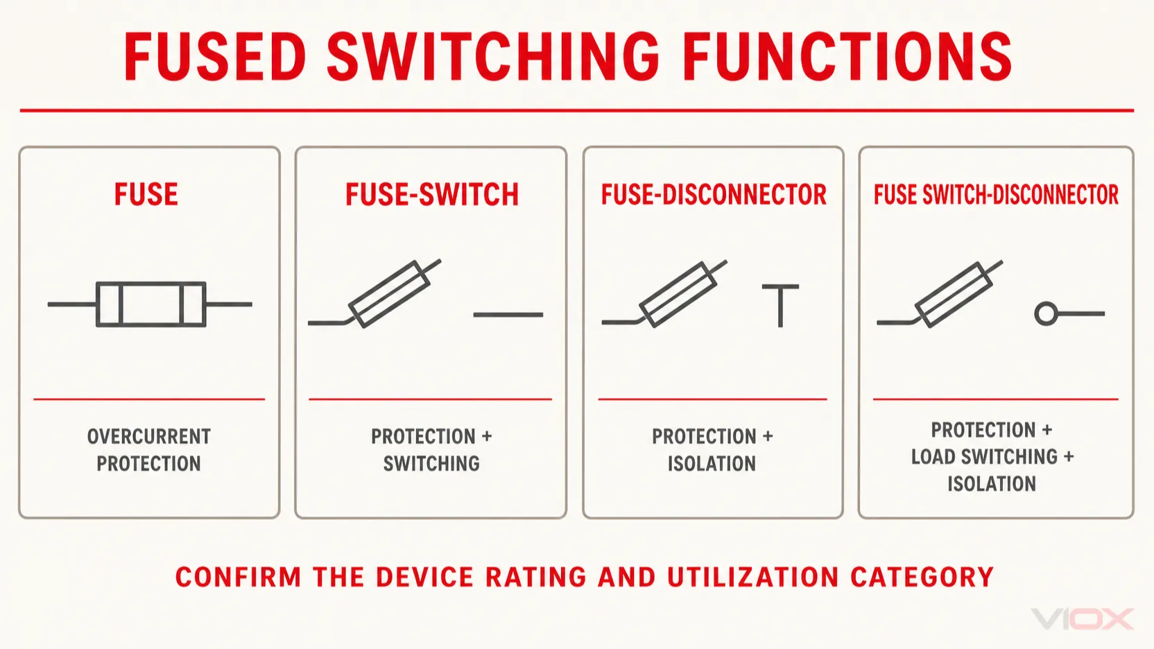
Jika lukisan memerlukan perlindungan arus lebih dan pengasingan penyelenggaraan yang selamat, sahkan fungsi peranti pensuisan yang lengkap dan bukannya menambah andaian pada simbol fius asas.
Simbol Fius lwn Simbol Pemutus Litar
Fius ialah peranti perlindungan arus lebih yang bersifat korban: pautan fius akan terbuka dan biasanya memerlukan penggantian. Pemutus litar terbuka melalui mekanisme pensuisan dan pelantikan mekanikal serta biasanya boleh ditetapkan semula selepas kerosakan disiasat dan pemutus litar masih boleh digunakan.
Simbolnya mesti kekal berbeza kerana tindakan penyelenggaraan adalah berlainan. Apabila mengesan kerosakan:
- rujukan fius merujuk kepada pautan fius dan pemegang yang berkaitan atau peranti pensuisan berfius;
- rujukan pemutus litar merujuk kepada peranti pensuisan dan perlindungan yang boleh ditetapkan semula;
- simbol gabungan mungkin menyampaikan lebih daripada satu fungsi dan mesti dibaca sebagai peranti yang lengkap.
Untuk perbezaan perlindungan dan pemilihan, lihat Fius lwn Pemutus Litar.
Kesilapan Biasa dalam Pentafsiran Simbol Fius
1. Menganggap simbol sebagai spesifikasi fius yang lengkap
Simbol mengenal pasti fungsi, bukan kadaran penuh. Sentiasa semak jadual komponen dan helaian data.
Mengandaikan simbol tersebut membuktikan kesesuaian AC atau DC
Kesesuaian AC/DC diperoleh daripada dokumentasi litar dan kadaran fius, bukan daripada simbol fius generik.
Membaca F, T, gG, dan pagi sebagai kod yang setara
Tanda-tanda ini datang daripada keluarga fius dan sistem klasifikasi yang berbeza. Maknanya mesti ditafsirkan mengikut piawaian yang terpakai.
Mengelirukan pemutus fius (fuse-disconnector) dengan peranti pemutus beban (load-break device)
Keupayaan pengasingan dan keupayaan pensuisan beban adalah fungsi yang berasingan. Sahkan simbol lengkap, kategori penggunaan, dan kadaran pengeluar.
Mengabaikan petunjuk (legend) lukisan
Simbol legasi, pustaka syarikat, dan varian CAD wujud. Legenda projek menentukan konvensyen yang digunakan oleh lukisan tersebut.
6. Menggantikan fius berdasarkan lukisan sahaja
Penggantian mestilah sepadan dengan arus, voltan, kapasiti pemutusan, kategori penggunaan, dimensi, keserasian pemegang, dan tugas penyelarasan yang diperlukan. Penampilan yang serupa tidak mencukupi.
Senarai Semak Semakan Lukisan Praktikal
Sebelum meluluskan atau menyelenggara litar berfius, jawab soalan-soalan ini:
- Apakah piawaian simbol dan legenda lukisan yang terpakai?
- Adakah peranti tersebut merupakan fius, suis fius, pemutus fius, atau suis-pemutus fius?
- Apakah penetapan rujukan tersebut?
- Di manakah keperluan arus, voltan, kapasiti pemutusan, dan kategori penggunaan didokumenkan?
- Adakah litar tersebut AC atau DC?
- Adakah fius yang dipasang sepadan dengan jadual yang diluluskan dan pemegang fius?
- Adakah sesentuh penggera atau penyerang (striker) ditunjukkan, dan ke manakah ia melaporkan atau melantik (trip)?
- Adakah pensuisan beban dibenarkan oleh kadaran peranti lengkap?
Sering Bertanya Soalan-Soalan
Apakah simbol elektrik bagi fius?
Ia merupakan simbol grafik yang dimasukkan secara bersiri dengan konduktor untuk menunjukkan fungsi fius. Sistem IEC dan ANSI/IEEE menggunakan perwakilan yang berbeza, jadi legenda lukisan perlu disemak sebelum mentafsir bentuk yang tepat.
Apakah simbol fius IEC?
IEC 60617 menyediakan simbol fius am dan simbol berkaitan untuk fungsi seperti fius penyerang (striker fuse), sesentuh penggera, suis fius, pemutus fius, dan suis pemutus fius. Gunakan pangkalan data IEC 60617 semasa atau pustaka CAD IEC yang diluluskan untuk geometri normatif.
Adakah simbol fius ANSI sama dengan simbol IEC?
Tidak semestinya. Lukisan ANSI/IEEE boleh menggunakan perwakilan melengkung atau bergaya yang berbeza. Lukisan Amerika Utara yang lebih lama mungkin juga menggunakan varian legasi. Sahkan pustaka simbol dan legenda IEEE/ANSI pada lukisan tersebut.
Adakah terdapat simbol fius DC yang berasingan?
Simbol fius asas biasanya kekal sama. Perkhidmatan DC biasanya dikenal pasti melalui litar sekeliling dan anotasi. Fius fizikal mestilah mempunyai kadaran voltan DC dan keupayaan pemutusan DC yang sesuai.
Lakukan F1 bermaksud fius tindakan pantas?
Biasanya F1 ialah penetapan rujukan yang mengenal pasti satu peranti dalam lukisan. Ia tidak boleh dikelirukan dengan F penandaan ciri pengendalian pada pautan fius kecil tertentu. Semak jadual lukisan dan piawaian fius yang berkenaan.
Bagaimanakah fius jenis 'slow-blow' ditunjukkan pada gambar rajah litar?
Banyak lukisan menggunakan simbol fius am berserta anotasi lengah masa, kod komponen, atau nombor bahagian. Jangan bergantung kepada simbol 'slow-blow' yang dianggap universal tanpa menyemak petunjuk (legend).
Adakah fius terma sama dengan fius biasa?
Tidak. Fius konvensional bertindak balas terhadap arus lebih mengikut ciri masa-arusnya. Fius terma atau pemutus terma akan terbuka apabila ambang suhunya dicapai. Kedua-dua peranti ini melindungi daripada keadaan utama yang berbeza.
Bolehkah pemegang fius digunakan sebagai suis pengasingan?
Tidak secara automatik. Keupayaan pemegang fius untuk menyediakan pengasingan yang selamat atau pensuisan beban mestilah disokong secara jelas oleh reka bentuk peranti, kadaran, piawaian yang berkenaan, dan arahan pengilang.
Kesimpulan
Cara terpantas untuk membaca simbol litar fius dengan betul adalah dengan memisahkan empat lapisan maklumat:
- Simbol grafik: fungsi elektrik yang ditunjukkan dalam litar.
- Penetapan rujukan: identiti peranti, seperti
F1. - Anotasi atau jadual: arus, voltan, perkhidmatan AC/DC, kategori penggunaan, dan kadaran lain yang diperlukan.
- Dokumentasi produk: fius yang disahkan, pemegang, fungsi pensuisan, kapasiti pemutusan, dan had pemasangan.
Simbol tersebut memberitahu anda di mana fungsi perlindungan terletak. Ia tidak menggantikan jadual fius atau helaian data. Apabila menilai Rangkaian fius VIOX atau pemasangan fius pembekal lain, serahkan voltan sistem, tugas AC/DC, arus beban, arus kerosakan prospektif, kategori penggunaan, format fius, serta fungsi pensuisan atau pengasingan yang diperlukan.