នៅលើទំព័រនេះ
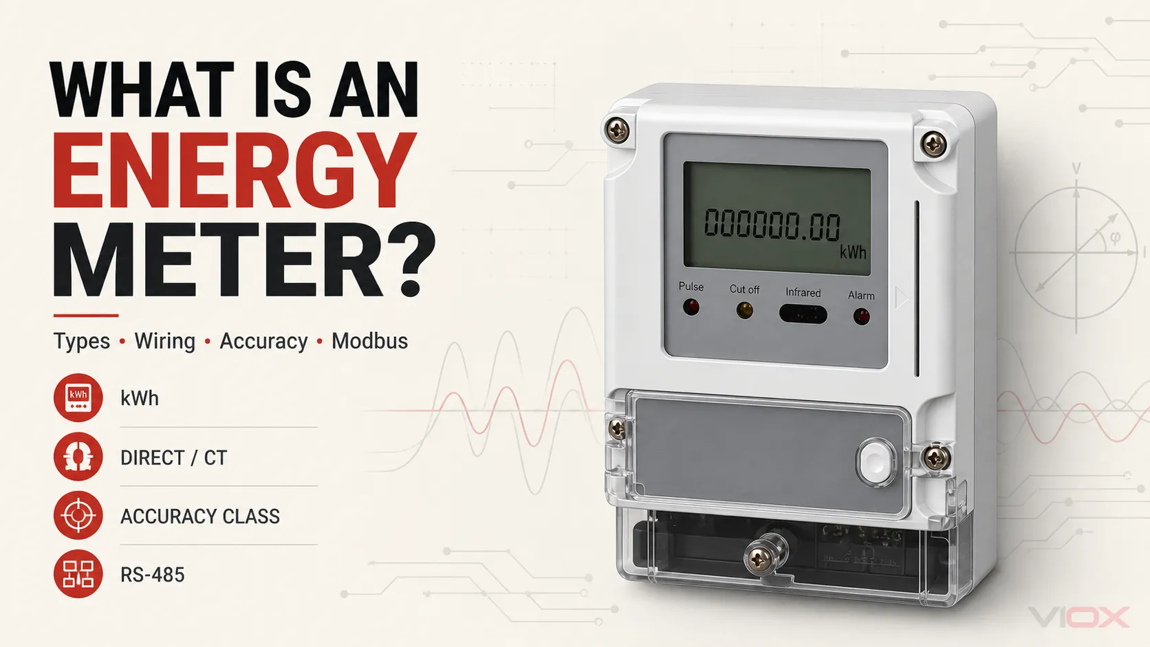
ក ម៉ែត្រវាស់ថាមពល គឺជាឧបករណ៍ដែលវាស់ថាមពលអគ្គិសនីដែលប្រមូលផ្តុំតាមពេលវេលា។ ថាមពលសកម្មជាធម្មតាត្រូវបានបង្ហាញជាគីឡូវ៉ាត់ម៉ោង (kWh) ខណៈពេលដែលម៉ែត្រដែលមានមុខងារបន្ថែមអាចកត់ត្រាថាមពលប្រតិកម្មជាគីឡូវ៉ារម៉ោង (kvarh), ថាមពលដែលនាំចូលនិងនាំចេញ, តម្រូវការ, វ៉ុល, ចរន្ត, កម្លាំង, និងកត្តាកម្លាំង។.
សម្រាប់បន្ទះតង់ស្យុងទាប ការជ្រើសរើសម៉ែត្រវាស់ថាមពលមិនមែនគ្រាន់តែជាបញ្ហានៃការជ្រើសរើសរវាងដំណាក់កាលតែមួយ (single-phase) ឬបីដំណាក់កាល (three-phase) នោះទេ។ ខ្សែសង្វាក់វាស់វែងពេញលេញមានបួនស្រទាប់៖
| ស្រទាប់ | សំណួរផ្នែកវិស្វកម្ម | អ្វីដែលត្រូវកំណត់ |
|---|---|---|
| ម៉ែត្រ | តើបរិមាណអ្វីខ្លះដែលត្រូវវាស់? | kWh, kvarh, តម្រូវការ, ថាមពលទ្វេទិស, តម្លៃភ្លាមៗ |
| ការតភ្ជាប់ | តើវ៉ុល និងចរន្តនឹងទៅដល់ម៉ែត្រដោយរបៀបណា? | ការតភ្ជាប់ដោយផ្ទាល់ ឬដំណើរការដោយប្លែងចរន្ត (CT); ការរៀបចំដំណាក់កាល និងខ្សែចម្លង |
| ភាពត្រឹមត្រូវ | តើភស្តុតាងអ្វីខ្លះដែលតម្រូវសម្រាប់កិច្ចការវាស់វែង? | ស្តង់ដារដែលអាចអនុវត្តបាន, ថ្នាក់ថាមពលសកម្ម ឬថាមពលប្រតិកម្ម, ថ្នាក់ CT, ជួរប្រតិបត្តិការ |
| ទំនាក់ទំនង | តើទិន្នន័យនឹងទៅដល់ប្រព័ន្ធគ្រប់គ្រងអគារ, PLC, ឬច្រកទ្វារ (gateway) ដោយរបៀបណា? | ទិន្នផលជីពចរ, Modbus RTU, Modbus TCP, អាសយដ្ឋាន, ការកំណត់ស៊េរី, និងផែនទីចុះបញ្ជី |
ម៉ែត្រដែលមានលក្ខណៈបច្ចេកទេសសមស្របត្រូវតែបំពេញតាមស្រទាប់ទាំងបួន។ ការបង្ហាញដែលមានភាពត្រឹមត្រូវខ្ពស់មិនអាចកែតម្រូវសមាមាត្រប្លែងចរន្ត (CT) ដែលខុស, ប៉ូល CT ដែលបញ្ច្រាស, ការខ្វះឯកសារយោងវ៉ុល, ឬការកំណត់មាត្រដ្ឋានចុះបញ្ជី Modbus ដែលមិនត្រឹមត្រូវនោះទេ។.
តើម៉ែត្រថាមពលវាស់វែងអ្វីខ្លះ?
ថាមពលអគ្គិសនីគឺជាអត្រានៃការផ្ទេរថាមពល។ ថាមពលអគ្គិសនីគឺជាថាមពលដែលប្រមូលផ្តុំតាមពេលវេលា៖
E = ∫ P(t) dtនៅពេលដែលថាមពលត្រូវបានបង្ហាញជាគីឡូវ៉ាត់ និងពេលវេលាជាម៉ោង លទ្ធផលគឺគីឡូវ៉ាត់ម៉ោង៖
E_kWh = ∫ P_kW(t) dtម៉ែត្រអេឡិចត្រូនិចធ្វើការវាស់គំរូនៃវ៉ុល និងចរន្ត កំណត់ទំនាក់ទំនងដំណាក់កាលរបស់វា គណនាថាមពល និងធ្វើការរួមបញ្ចូលថាមពលនោះតាមពេលវេលា។ នៅក្នុងប្រព័ន្ធបីដំណាក់កាល វាអនុវត្តការគណនាសម្រាប់ធាតុដំណាក់កាលដែលពាក់ព័ន្ធ និងរួមបញ្ចូលលទ្ធផលទៅតាមការកំណត់រចនាសម្ព័ន្ធនៃការតភ្ជាប់របស់វា។.
ភាពខុសគ្នារវាងថាមពល និងថាមពលអគ្គិសនីនេះគឺមានសារៈសំខាន់ជាមូលដ្ឋាន។ បន្ទុក 20 kW ដែលដំណើរការយ៉ាងទៀងទាត់រយៈពេលបីម៉ោងនឹងប្រើប្រាស់ថាមពលប្រហែល 60 kWh។ សម្រាប់ការបកស្រាយលម្អិតបន្ថែម សូមមើល kW ទល់នឹង kWh៖ តើមានអ្វីខុសគ្នា?.
អាស្រ័យលើការរចនារបស់វា ម៉ែត្រអាចផ្តល់ជូននូវ៖
- ថាមពលសកម្មគិតជា kWh;
- ថាមពលប្រតិកម្មគិតជា kvarh;
- ថាមពលជាក់ស្តែងគិតជា kVAh;
- ថាមពលដែលនាំចូល និងនាំចេញនៅក្នុងបញ្ជីកត់ត្រាដាច់ដោយឡែកពីគ្នា;
- វ៉ុលភ្លាមៗ, ចរន្ត, ប្រេកង់, ថាមពលសកម្ម, ថាមពលប្រតិកម្ម, ថាមពលជាក់ស្តែង និងកត្តាថាមពល;
- តម្រូវការអតិបរិមានៅក្នុងចន្លោះពេលដែលបានកំណត់;
- ទិន្នផលជីពចរ ឬការទំនាក់ទំនងឌីជីថលសម្រាប់ការប្រមូលទិន្នន័យពីចម្ងាយ។.
បរិមាណដែលត្រូវការត្រូវតែបញ្ជាក់ឱ្យបានច្បាស់លាស់។ ឧបករណ៍ដែលបង្ហាញចរន្ត និងវ៉ុល មិនមែនមានន័យថាជាម៉ែត្រវាស់ថាមពលសម្រាប់គិតថ្លៃដែលអនុលោមតាមស្តង់ដារដោយស្វ័យប្រវត្តិនោះទេ ហើយម៉ែត្រវាស់ kWh ក៏មិនមែនជាឧបករណ៍វិភាគគុណភាពថាមពលដោយស្វ័យប្រវត្តិនោះដែរ។.
ម៉ែត្រវាស់ថាមពល ទល់នឹង ម៉ែត្រវាស់កម្លាំងអគ្គិសនី ទល់នឹង ម៉ែត្រឆ្លាតវៃ
ពាក្យទាំងនេះមានការត្រួតស៊ីគ្នានៅក្នុងកាតាឡុកផលិតផល ប៉ុន្តែវាមិនបានពិពណ៌នាអំពីមុខងារដូចគ្នាបេះបិទនោះទេ។.
| ពាក្យ | មុខងារចម្បង | លទ្ធផលទូទៅ | ព្រំដែនសំខាន់ |
|---|---|---|---|
| ម៉ែត្រវាស់ថាមពល | ប្រមូលផ្តុំថាមពលអគ្គិសនីតាមពេលវេលា | kWh និងអាស្រ័យលើម៉ូដែល អាចមាន kvarh ឬបញ្ជីកត់ត្រាការនាំចូល/នាំចេញ | ភាពត្រឹមត្រូវ និងការប្រើប្រាស់ស្របច្បាប់គឺអាស្រ័យលើស្តង់ដារ និងកម្មវិធីដែលបានប្រកាស |
| ឧបករណ៍វាស់ថាមពលអគ្គិសនី | វាស់ និងត្រួតពិនិត្យបរិមាណអគ្គិសនី | V, A, kW, kvar, kVA, ប្រេកង់, កត្តាថាមពល, តម្រូវការថាមពល និងពេលខ្លះថាមពលសរុប | ឧបករណ៍វាស់ និងត្រួតពិនិត្យថាមពលអគ្គិសនីអាចស្ថិតនៅក្រោមវិសាលភាពស្តង់ដារខុសពីឧបករណ៍វាស់អគ្គិសនីទូទៅ |
| ឧបករណ៍វាស់ឆ្លាតវៃ | បន្ថែមមុខងារទំនាក់ទំនង ការគ្រប់គ្រងទិន្នន័យ តារាងតម្លៃ ឬមុខងារពីចម្ងាយទៅលើការវាស់វែង | កំណត់ត្រាថាមពល ទិន្នន័យតាមចន្លោះពេល ព្រឹត្តិការណ៍ និងការទំនាក់ទំនងពីចម្ងាយ | “ពាក្យថា ”ឆ្លាតវៃ" ពិពណ៌នាអំពីមុខងារដែលបានបន្ថែម ប៉ុន្តែវាមិនបានបញ្ជាក់ដោយខ្លួនឯងអំពីថ្នាក់ភាពត្រឹមត្រូវ ឬវិធីសាស្ត្រតភ្ជាប់នោះទេ |
| ឧបករណ៍វាស់គុណភាពថាមពលអគ្គិសនី | វាយតម្លៃការរំខាន និងប៉ារ៉ាម៉ែត្រគុណភាពថាមពលអគ្គិសនី | អាម៉ូនិក (Harmonics), ការធ្លាក់ចុះវ៉ុល (dips), ការកើនឡើងវ៉ុល (swells), ការដាច់ចរន្ត (interruptions), ភាពមិនមានតុល្យភាព (unbalance) និងព្រឹត្តិការណ៍ផ្សេងៗទៀត | ម៉ែត្រវាស់ថាមពលពហុមុខងារ មិនមែនជាឧបករណ៍វាស់គុណភាពថាមពលអគ្គិសនីដែលអនុលោមតាមស្តង់ដារដោយស្វ័យប្រវត្តិនោះទេ |
IEC 61557-12 និយាយអំពីឧបករណ៍វាស់ និងត្រួតពិនិត្យថាមពលអគ្គិសនីដែលប្រើក្នុងប្រព័ន្ធចែកចាយអគ្គិសនីតាមរោងចក្រឧស្សាហកម្ម និងពាណិជ្ជកម្ម ខណៈពេលដែលក្រុមស្តង់ដារ IEC 62052 និង IEC 62053 និយាយអំពីឧបករណ៍វាស់វែងអគ្គិសនី និងតម្រូវការភាពត្រឹមត្រូវរបស់វា។ សេចក្តីប្រកាសអនុលោមភាពដែលមានសុពលភាពមានសារៈសំខាន់ជាងឈ្មោះទីផ្សារដែលបង្ហាញនៅលើបន្ទះខាងមុខ។.
តើម៉ែត្រវាស់ថាមពលអគ្គិសនីបែបអេឡិចត្រូនិកដំណើរការយ៉ាងដូចម្តេច?
ម៉ែត្រវាស់ថាមពលអគ្គិសនីបែបឋិតិវន្ត (static meter) សម័យទំនើប ជាទូទៅមានដំណាក់កាលមុខងារចំនួនបួន។.
១. ការចាប់សញ្ញាវ៉ុល
ម៉ែត្រទទួលបានឯកសារយោងវ៉ុលសម្រាប់ដំណាក់កាលនីមួយៗដែលបានវាស់វែង។ បណ្តាញបញ្ចូលធ្វើការកំណត់មាត្រដ្ឋាន និងញែកសញ្ញាតាមតម្រូវការនៃការរចនាខាងក្នុង។.
២. ការចាប់សញ្ញាចរន្ត
ម៉ែត្រដែលតភ្ជាប់ដោយផ្ទាល់ផ្ទុកចរន្តផ្ទុកតាមរយៈផ្លូវចរន្តខាងក្នុងរបស់វា។ ម៉ែត្រដែលដំណើរការដោយត្រង់ស្្វ័រទទួលបានចរន្តបន្ទាប់បន្សំដែលបានកំណត់មាត្រដ្ឋានពីត្រង់ស្្វ័រចរន្ត (CTs) ខាងក្រៅ។ ប្រព័ន្ធឯកទេសមួយចំនួនប្រើត្រង់ស្្វ័រឧបករណ៍ថាមពលទាប ប៉ុន្តែការអនុលោមតាមច្បាប់ និងច្បាប់តភ្ជាប់របស់វាទាមទារឱ្យមានការផ្ទៀងផ្ទាត់ដាច់ដោយឡែក។.
៣. ការគណនាឌីជីថល
សៀគ្វីវាស់វែងធ្វើការយកគំរូនៃទម្រង់រលកវ៉ុល និងចរន្ត។ វាគណនាថាមពលភ្លាមៗ និងបញ្ចូលលទ្ធផលទៅក្នុងបញ្ជីថាមពល។ ម៉ែត្រពហុមុខងារក៏អាចគណនាពីតម្រូវការ កត្តាថាមពល ប្រេកង់ ភាពមិនស្មើគ្នានៃដំណាក់កាល និងសូចនាករអាម៉ូនិកផងដែរ។.
៤. ការបង្ហាញ និងទិន្នន័យចេញ
លទ្ធផលដែលប្រមូលបានអាចត្រូវបានបង្ហាញនៅលើអេក្រង់ បញ្ចេញជាជីពចរដែលបានក្រិតតាមខ្នាត ឬបង្ហាញតាមរយៈចំណុចប្រទាក់ទំនាក់ទំនង។ ថេរជីពចរដូចជាចំនួនជីពចរក្នុងមួយ kWh គឺអាស្រ័យលើម៉ូដែលជាក់លាក់ ហើយត្រូវតែអានពីស្លាកឈ្មោះម៉ែត្រ ឬសន្លឹកទិន្នន័យ។.
ប្រភេទសំខាន់ៗនៃម៉ែត្រថាមពល
មិនមានបញ្ជីតែមួយដែលមានប្រយោជន៍សម្រាប់ប្រភេទម៉ែត្រវាស់ថាមពលនោះទេ ពីព្រោះម៉ែត្រអាចត្រូវបានចាត់ថ្នាក់តាមបច្ចេកវិទ្យាវាស់វែង ប្រព័ន្ធអគ្គិសនី វិធីសាស្ត្រតភ្ជាប់ មុខងារ និងទម្រង់នៃការដំឡើង។.
| ចំណាត់ថ្នាក់ | ជម្រើសសំខាន់ៗ | សារៈសំខាន់នៃការជ្រើសរើស |
|---|---|---|
| បច្ចេកវិទ្យាវាស់វែង | អេឡិចត្រូមេកានិចអាំងឌុចស្យុង; អេឡិចត្រូនិចឋិតិវន្ត | ការរចនាបែបអេឡិចត្រូនិចអនុញ្ញាតឱ្យមានទម្រង់ DIN-rail ដែលមានទំហំតូច ឧបករណ៍ចុះបញ្ជីច្រើន និងការទំនាក់ទំនង |
| ប្រព័ន្ធផ្គត់ផ្គង់ថាមពល | ហ្វាសតែមួយ; បីហ្វាស | ត្រូវតែផ្គូផ្គងនឹងហ្វាសជាក់ស្តែង និងការរៀបចំខ្សែចម្លង |
| ការតភ្ជាប់ចរន្ត | ការតភ្ជាប់ដោយផ្ទាល់; ការប្រតិបត្តិដោយ CT | កំណត់ផ្លូវចរន្ត វិធីសាស្ត្រតភ្ជាប់ខ្សែ ការកំណត់រចនាសម្ព័ន្ធ CT និងនីតិវិធីដាក់ឱ្យដំណើរការ |
| ទិសដៅថាមពល | ការនាំចូលតែប៉ុណ្ណោះ; ការនាំចូល/នាំចេញទ្វេដង | ការវាស់វែងទ្វេដងមានសារៈសំខាន់សម្រាប់ប្រព័ន្ធសូឡា ប្រព័ន្ធផ្ទុកថាមពល និងការដំឡើងប្រព័ន្ធផលិតថាមពលផ្សេងទៀត |
| មុខងារ | ថាមពលតែប៉ុណ្ណោះ; ពហុមុខងារ; តម្រូវការ; តារាងតម្លៃ; បង់ប្រាក់ជាមុន | កំណត់បញ្ជីឈ្មោះ លទ្ធផលទិន្នផល ទំព័របង្ហាញ និងតម្រូវការនៃការរួមបញ្ចូល |
| ទំនាក់ទំនង | Pulse តែមួយគត់; RS-485 Modbus RTU; Ethernet Modbus TCP; ប្រូតូកូលផ្សេងទៀត | ត្រូវតែផ្គូផ្គងជាមួយ gateway, PLC, BMS ឬវេទិកាគ្រប់គ្រងថាមពល |
| ការម៉ោន | DIN rail; ការកាត់ផ្ទាំងបន្ទះ; រន្ធដោត ឬប្រអប់ម៉ែត្រដែលបានកំណត់ | ជះឥទ្ធិពលដល់ប្លង់បន្ទះ ការចូលទៅកាន់ស្ថានីយ ការផ្សាភ្ជាប់ និងនីតិវិធីថែទាំ |
ម៉ែត្រថាមពលហ្វាសតែមួយ
ម៉ែត្រហ្វាសតែមួយត្រូវបានប្រើនៅកន្លែងដែលសៀគ្វីវាស់មានខ្សែហ្វាសមួយ និងខ្សែណឺត ឬការរៀបចំការតភ្ជាប់ផ្សេងទៀតដែលត្រូវបានគាំទ្រយ៉ាងច្បាស់លាស់ដោយក្រុមហ៊ុនផលិត។ វាជារឿងធម្មតានៅក្នុងសៀគ្វីសាខា បន្ទុកពាណិជ្ជកម្មខ្នាតតូច ការត្រួតពិនិត្យកម្រិតឧបករណ៍ និងការចែកចាយក្នុងលំនៅដ្ឋាន។.
ម៉ែត្រថាមពលបីហ្វាស
ម៉ែត្របីហ្វាសវាស់សៀគ្វីពហុហ្វាស។ ការតភ្ជាប់ជាក់លាក់អាស្រ័យលើថាតើប្រព័ន្ធជាប្រភេទបីខ្សែ ឬបួនខ្សែ និងថាតើម៉ែត្រត្រូវបានតភ្ជាប់ដោយផ្ទាល់ ឬដំណើរការដោយ CT។ ម៉ែត្រត្រូវតែគាំទ្រដល់ topology ជាក់ស្តែង; ការកំណត់រចនាសម្ព័ន្ធកម្មវិធីមិនអាចកែតម្រូវធាតុវាស់ដែលមិនឆបគ្នាជាមូលដ្ឋានបានទេ។.
សម្រាប់មូលដ្ឋានគ្រឹះនៃប្រព័ន្ធ សូមមើល មួយហ្វាធៀបនឹងបីហ្វា: តើអ្វីជាភាពខុសគ្នា?.
ម៉ែត្រថាមពលប្រភេទតភ្ជាប់ផ្ទាល់
នៅក្នុងម៉ែត្រប្រភេទតភ្ជាប់ផ្ទាល់ ចរន្តផ្ទុកនឹងឆ្លងកាត់តាមស្ថានីយចរន្តរបស់ម៉ែត្រ។ នេះអាចជួយសម្រួលដល់ការដំឡើងសៀគ្វីតូចៗ ប៉ុន្តែជួរចរន្តដែលបានកំណត់របស់ម៉ែត្រ សមត្ថភាពខ្សែចំលង តម្រូវការស្ថានីយ កម្រិតសីតុណ្ហភាព និងការសម្របសម្រួលឧបករណ៍ការពារ ទាំងអស់ត្រូវតែសមស្របនឹងសៀគ្វីនោះ។.
មិនមានដែនកំណត់ចរន្តសម្រាប់ការតភ្ជាប់ផ្ទាល់ជាសកលនោះទេ។ តម្លៃត្រឹមត្រូវគឺអាស្រ័យលើដែនកំណត់ដែលបានកំណត់សម្រាប់ម៉ែត្រជាក់លាក់ និងវិធីសាស្ត្រដំឡើងនោះ។.
ម៉ែត្រថាមពលប្រភេទដំណើរការដោយ CT
ម៉ែត្រប្រភេទដំណើរការដោយ CT ទទួលបានចរន្តបន្ទាប់បន្សំដែលបានកំណត់ស្តង់ដារ ឬបានបញ្ជាក់ពីឧបករណ៍បំលែងចរន្តខាងក្រៅ។ ការរៀបចំនេះអនុញ្ញាតឱ្យម៉ែត្រវាស់វែងសៀគ្វីដែលមានចរន្តបឋមលើសពីផ្លូវចរន្តផ្ទាល់របស់ម៉ែត្រ និងជួយសម្រួលដល់ការរៀបចំផ្ទាំងបញ្ជាសម្រាប់ខ្សែមេដែលមានទំហំធំជាង។.
សមាមាត្របឋមរបស់ CT, កម្រិតបន្ទាប់បន្សំ, ថ្នាក់ភាពត្រឹមត្រូវ, បន្ទុក (burden), ប៉ូល (polarity), ការកំណត់ដំណាក់កាល និងការកំណត់រចនាសម្ព័ន្ធម៉ែត្រ បង្កើតបានជាប្រព័ន្ធវាស់វែងមួយ។ ស្វែងយល់បន្ថែមអំពីឧបករណ៍ចាប់សញ្ញានៅក្នុង ឧបករណ៍បំលែងចរន្ត (CT) ទល់នឹងឧបករណ៍បំលែងតង់ស្យុង (PT).
ការតភ្ជាប់ខ្សែម៉ែត្រវាស់ថាមពល៖ ការតភ្ជាប់ដោយផ្ទាល់ ទល់នឹង ការតភ្ជាប់តាមរយៈ CT
ការតភ្ជាប់ខ្សែម៉ែត្រវាស់ថាមពលត្រូវតែអនុវត្តតាមដ្យាក្រាមដែលបានផ្តល់ជូនសម្រាប់ម៉ូដែលជាក់លាក់។ លេខស្ថានីយមានភាពខុសគ្នា ហើយដ្យាក្រាមសម្រាប់ម៉ែត្រមួយមិនអាចយកទៅប្រើសម្រាប់ម៉ែត្រមួយទៀតដោយសុវត្ថិភាពបានឡើយ គ្រាន់តែដោយសារឧបករណ៍ទាំងពីរជាប្រភេទបីហ្វាស ឬដំឡើងនៅលើ DIN-rail នោះទេ។.
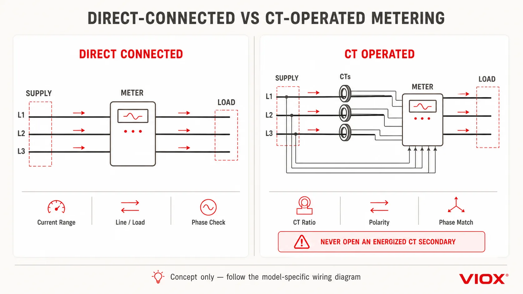
តារាងខាងក្រោមពន្យល់អំពីស្ថាបត្យកម្ម មិនមែនជាការណែនាំអំពីការដំឡើងតាមស្ថានីយនីមួយៗនោះទេ។.
| ចំណុចតភ្ជាប់ | ម៉ែត្រតភ្ជាប់ដោយផ្ទាល់ | ម៉ែត្រតភ្ជាប់តាមរយៈ CT |
|---|---|---|
| ផ្លូវចរន្ត | ចរន្តផ្ទុកឆ្លងកាត់ស្ថានីយចរន្តរបស់ម៉ែត្រ | ម៉ែត្រទទួលបានចរន្តបន្ទាប់បន្សំពី CT |
| ឯកសារយោងវ៉ុល | ភ្ជាប់ទៅនឹងហ្វាសដែលបានវាស់វែង ឬហ្វាសនានាដូចដែលបានបញ្ជាក់ | ភ្ជាប់ដោយឡែកទៅនឹងហ្វាសដែលបានវាស់វែង ឬហ្វាសនានាដូចដែលបានបញ្ជាក់ |
| ការកំណត់មាត្រដ្ឋាន | ផ្អែកលើជួរចរន្តផ្ទាល់របស់ម៉ែត្រ | សមាមាត្រចម្បងទៅបន្ទាប់បន្សំរបស់ CT ត្រូវតែបញ្ចូល ឬអនុវត្តឱ្យបានត្រឹមត្រូវ |
| ហានិភ័យនៃប៉ូលមេ | ការបញ្ច្រាសទិសដៅនៃការផ្គត់ផ្គង់/បន្ទុក អាចធ្វើឱ្យទិសដៅថាមពលបញ្ច្រាសនៅលើម៉ែត្រដែលពាក់ព័ន្ធ | ប៉ូលារបស់ CT ដែលដាក់បញ្ច្រាសអាចបង្កើតថាមពលអវិជ្ជមាន ការចុះបញ្ជីការនាំចេញ ឬកំហុសផលបូកដំណាក់កាល |
| ការផ្ដាច់ប្រព័ន្ធសេវាកម្ម | តម្រូវឱ្យមានការរៀបចំការផ្ដាច់ និងការការពាររបស់អ្នកផលិត | ជាធម្មតាទាមទារឱ្យមានការរៀបចំការធ្វើតេស្ត និងការធ្វើសៀគ្វីខ្លី CT ប្រកបដោយសុវត្ថិភាពនៅកន្លែងដែលអាចអនុវត្តបាន |
| ការត្រួតពិនិត្យការដាក់ឱ្យដំណើរការធម្មតា | ផ្ទៀងផ្ទាត់ដំណាក់កាល ទិសដៅ ចរន្ត វ៉ុល និងថាមពលដែលប្រមូលផ្ដុំ | ផ្ទៀងផ្ទាត់ផងដែរនូវសមាមាត្រ CT ប៉ូលា S1/S2 ការភ្ជាប់ដំណាក់កាល និងភាពបន្តនៃបន្ទាប់បន្សំ |
គន្លងតភ្ជាប់ដោយផ្ទាល់តាមគោលគំនិត
ចំហាយផ្គត់ផ្គង់ និងចំហាយផ្ទុកត្រូវតភ្ជាប់តាមរយៈម៉ែត្រយោងទៅតាមដ្យាក្រាមខ្សែ/ផ្ទុករបស់អ្នកផលិត ខណៈពេលដែលការវាស់វែងវ៉ុលត្រូវបានដកស្រង់ចេញពីស្ថានីយដែលបានកំណត់។ អ្នកដំឡើងត្រូវតែផ្ទៀងផ្ទាត់លំដាប់ហ្វាស ការរៀបចំខ្សែណឺត ទំហំចំហាយ កម្លាំងបង្វិលជិត (tightening torque) ការការពារនៅផ្នែកខាងលើ (upstream protection) និងថាតើឧបករណ៍ការពារសៀគ្វីវ៉ុលដាច់ដោយឡែកមួយត្រូវបានទាមទារដែរឬទេ។.
គន្លងប្រតិបត្តិការដោយ CT តាមគំនិត
CT នីមួយៗត្រូវតែដំឡើងនៅលើហ្វាសដែលបានកំណត់ និងតម្រង់ទិសក្នុងទិសដៅចម្បងដែលបានប្រកាស។ ចំហាយបន្ទាប់បន្សំរបស់វាត្រូវតភ្ជាប់ទៅនឹងច្រកបញ្ចូលចរន្តរបស់ម៉ែត្រដែលត្រូវគ្នា ខណៈពេលដែលម៉ែត្រទទួលបានឯកសារយោងវ៉ុលពីហ្វាសអគ្គិសនីតែមួយ។ សមាមាត្រ CT ដែលបានកំណត់រចនាសម្ព័ន្ធត្រូវតែផ្គូផ្គងនឹងសមាមាត្រ CT ដែលបានដំឡើង។.
ច្បាប់សុវត្ថិភាព CT ដ៏សំខាន់៖ កុំទុកផ្នែកបន្ទាប់បន្សំនៃប្លែងចរន្តធម្មតាឱ្យនៅចំហ (open) នៅពេលដែលចរន្តចម្បងកំពុងហូរ។ ត្រូវប្រើប្លុកតភ្ជាប់សៀគ្វីខ្លី (shorting block) កុងតាក់តេស្ត នីតិវិធីផ្ដាច់ចរន្ត និងឧបករណ៍ការពារផ្ទាល់ខ្លួនដែលបានកំណត់។ ការដំឡើង និងការដាក់ឱ្យដំណើរការត្រូវតែអនុវត្តដោយបុគ្គលិកដែលមានសមត្ថភាព ដោយមានសៀគ្វីដាច់ចេញពីប្រភពនៅកន្លែងដែលការងារតម្រូវឱ្យធ្វើបែបនោះ។.
កំហុសក្នុងការវាស់វែងទូទៅបន្ទាប់ពីការតភ្ជាប់ខ្សែ
- CT មួយត្រូវបានកំណត់ទៅហ្វាសវ៉ុលខុស;
- CT មួយត្រូវបានដាក់បញ្ច្រាស ដែលបណ្តាលឱ្យមានថាមពលអវិជ្ជមាន ឬផលបូកនៃការនាំចូល/នាំចេញមិនត្រឹមត្រូវ;
- សមាមាត្រ CT នៅក្នុងម៉ែត្រមិនត្រូវគ្នានឹងសមាមាត្រនៅលើផ្លាកឈ្មោះឡើយ។;
- ម៉ែត្រត្រូវបានកំណត់រចនាសម្ព័ន្ធសម្រាប់ប្រព័ន្ធបីហ្វារបួនខ្សែ ខណៈពេលដែលវាត្រូវបានតភ្ជាប់ទៅនឹងប្រព័ន្ធបីខ្សែ ឬផ្ទុយមកវិញ។;
- ហ្វុយស៊ីបយោងវ៉ុលដាច់ ដែលបណ្តាលឱ្យហ្វារមួយអានបានសូន្យ ឬធ្វើឱ្យតម្លៃសរុបមានការខុសប្រក្រតី។;
- ខ្សែណឺត (neutral) ត្រូវបានខកខានមិនបានតភ្ជាប់ ក្នុងករណីដែលថូប៉ូឡូជីដែលបានជ្រើសរើសតម្រូវឱ្យមានវា។;
- ការកំណត់មាត្រដ្ឋាន Modbus មិនត្រឹមត្រូវ ទោះបីជាការបង្ហាញនៅលើអេក្រង់មូលដ្ឋានមានភាពត្រឹមត្រូវក៏ដោយ។.
ការធ្វើតេស្តចុងក្រោយគួរតែប្រៀបធៀបចរន្តហ្វារ កម្លាំងហ្វារ កម្លាំងសរុប កត្តាកម្លាំង និងទិសដៅថាមពល ធៀបនឹងលក្ខខណ្ឌប្រតិបត្តិការដែលបានដឹង។ កុំទទួលយកតម្លៃ kWh សរុបដែលមើលទៅសមហេតុផល ដោយមិនបានពិនិត្យទិន្នន័យកម្រិតហ្វារ។.
ការពន្យល់អំពីថ្នាក់ភាពត្រឹមត្រូវនៃម៉ែត្រថាមពល
ថ្នាក់ភាពត្រឹមត្រូវគឺជាប្រភេទសមត្ថភាពការងារដែលកំណត់ដោយស្តង់ដារ ដែលត្រូវបានធ្វើតេស្តនៅចំណុចចរន្ត កត្តាកម្លាំង លក្ខខណ្ឌយោង និងលក្ខខណ្ឌឥទ្ធិពលដែលបានបញ្ជាក់។ វាត្រូវតែមិនត្រូវបានបកស្រាយថាជាការធានាជាសកលថាគ្រប់តម្លៃដែលបង្ហាញគឺស្ថិតនៅក្នុងលេខថ្នាក់នោះជានិច្ចក្នុងនាមជាភាគរយថេរឡើយ។.
ក្របខ័ណ្ឌ IEC បច្ចុប្បន្នបែងចែកតម្រូវការទូទៅចេញពីតម្រូវការជាក់លាក់នៃថ្នាក់ភាពត្រឹមត្រូវ។.
| ស្តង់ដារ | វិសាលភាពសំខាន់ដែលពាក់ព័ន្ធនឹងអត្ថបទនេះ | ថ្នាក់ ឬព្រំដែន |
|---|---|---|
| IEC 62052-11:2020 | តម្រូវការទូទៅ ការធ្វើតេស្ត លក្ខខណ្ឌនៃការធ្វើតេស្ត ការសម្គាល់ និងទិដ្ឋភាពទូទៅនៃការធ្វើតេស្តភាពត្រឹមត្រូវសម្រាប់ម៉ែត្រអគ្គិសនី AC និង DC | មិនកំណត់ថ្នាក់ថាមពលសកម្មដោយខ្លួនឯងនោះទេ |
| IEC 62052-31:2024 | តម្រូវការសុវត្ថិភាពផលិតផល និងការធ្វើតេស្តប្រភេទដែលពាក់ព័ន្ធសម្រាប់ឧបករណ៍វាស់វែងអគ្គិសនី | វិសាលភាពសុវត្ថិភាព មិនមែនជាថ្នាក់ភាពត្រឹមត្រូវនៃថាមពលទេ |
| IEC 62053-21:2020 | ម៉ែត្រឋិតិវន្តសម្រាប់ថាមពលសកម្ម AC | ថ្នាក់ 0.5, 1, និង 2 |
| IEC 62053-22:2020 | ម៉ែត្រឋិតិវន្តដំណើរការដោយត្រង់ស្វ័រសម្រាប់ថាមពលសកម្ម AC | ថ្នាក់ 0.1S, 0.2S, និង 0.5S |
| IEC 62053-24:2020 | ម៉ែត្រឋិតិវន្តសម្រាប់ថាមពលប្រតិកម្មនៃសមាសភាគមូលដ្ឋាន | ថ្នាក់ 0.5S, 1S, 1, 2, និង 3 |
| IEC 61557-12:2018+AMD1:2021 | ឧបករណ៍វាស់វែង និងត្រួតពិនិត្យថាមពលសម្រាប់ប្រព័ន្ធចែកចាយអគ្គិសនីក្នុងឧស្សាហកម្ម និងពាណិជ្ជកម្ម | ក្របខ័ណ្ឌឧបករណ៍ និងសមត្ថភាពការងារខុសគ្នា ដែលមិនអាចប្រើជំនួសគ្នាជាមួយការប្រកាសតាមស្តង់ដារ IEC 62053 បានឡើយ |
តើបច្ច័យ S មានន័យដូចម្តេច?
ថ្នាក់ S នៅក្នុង IEC 62053-22 អនុវត្តចំពោះម៉ែត្រថាមពលសកម្មដែលដំណើរការដោយត្រង់ស្្វ័រម៉ាទ័រ ហើយរួមបញ្ចូលនូវតម្រូវការសមត្ថភាពការងារជាក់លាក់តាមថ្នាក់នៅទូទាំងចំណុចប្រតិបត្តិការដែលបានកំណត់ រួមទាំងលក្ខខណ្ឌចរន្តទាបផងដែរ។ បច្ច័យនេះមិនគួរត្រូវបានបកស្រាយដោយផ្អែកលើឈ្មោះតែមួយមុខនោះទេ។ ឯកសារលទ្ធកម្មគួរតែយោងទៅតាមស្តង់ដារពេញលេញ ថ្នាក់ វិធីសាស្ត្រតភ្ជាប់ និងការបោះពុម្ពផ្សាយដែលតម្រូវដោយគម្រោង។.
ភាពត្រឹមត្រូវរបស់ម៉ែត្រមិនមែនជាភាពត្រឹមត្រូវរបស់ប្រព័ន្ធនោះទេ
សម្រាប់ការដំឡើងដែលដំណើរការដោយ CT លទ្ធផលចុងក្រោយត្រូវបានជះឥទ្ធិពលដោយកត្តាលើសពីម៉ែត្រ៖
- ភាពត្រឹមត្រូវនៃម៉ែត្រ និងជួរប្រតិបត្តិការ;
- កំហុសនៃសមាមាត្រ CT និងការផ្លាស់ប្តូរដំណាក់កាល;
- បន្ទុក CT និងលក្ខណៈនៃខ្សែនាំចរន្តបន្ទាប់បន្សំ;
- ការកំណត់ដំណាក់កាល និងប៉ូល;
- ភាពត្រឹមត្រូវនៃវ៉ុលយោង និងភាពបន្ត;
- សមាមាត្រត្រង់ស្្វ័រម៉ាទ័រដែលបានកំណត់រចនាសម្ព័ន្ធ;
- បរិយាកាសដំឡើង និងគុណភាពនៃការដាក់ឱ្យដំណើរការ។.
ការកំណត់យកម៉ែត្រកម្រិត Class 0.2S មិនធ្វើឱ្យសៀគ្វី CT ដែលជ្រើសរើសមិនត្រឹមត្រូវ ឬតភ្ជាប់ខុស ក្លាយជាប្រព័ន្ធវាស់វែងកម្រិត Class 0.2S នោះទេ។ គម្រោងត្រូវតែវាយតម្លៃខ្សែសង្វាក់វាស់វែងទាំងមូល និងច្បាប់វាស់វែងស្របច្បាប់ក្នុងតំបន់ណាមួយដែលអនុវត្តចំពោះការចេញវិក្កយបត្រ ឬការទូទាត់។.
តើម៉ែត្រថាមពល Modbus ជាអ្វី?
ម៉ែត្រថាមពល Modbus បង្ហាញតម្លៃដែលបានវាស់វែងតាមរយៈពិធីការកម្មវិធី Modbus។ នៅក្នុងបន្ទះអគ្គិសនីតង់ស្យុងទាប ការអនុវត្តទូទៅគឺ Modbus RTU លើបណ្តាញសៀរៀល RS-485។ ម៉ែត្រមួយចំនួនគាំទ្រ Modbus TCP លើ Ethernet។.
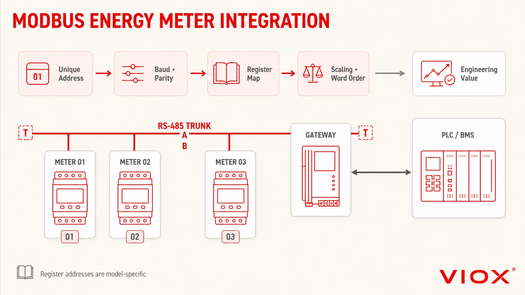
Modbus កំណត់ក្របខ័ណ្ឌផ្ញើសារសំណើ/ឆ្លើយតប និងកូដមុខងារ។ វាមិន មិន កំណត់ផែនទីចុះបញ្ជីម៉ែត្រថាមពលជាសកលនោះទេ។ ម៉ែត្រ Modbus ពីរអាចរក្សាទុកតម្លៃ kWh សរុបនៅអាសយដ្ឋានផ្សេងគ្នា ប្រើការកំណត់មាត្រដ្ឋានខុសគ្នា ឬកំណត់កូដតម្លៃដូចគ្នានៅក្នុងលំដាប់ពាក្យខុសគ្នា។.
បញ្ជីត្រួតពិនិត្យការតភ្ជាប់ខ្សែ និងការកំណត់រចនាសម្ព័ន្ធ Modbus RTU
| ធាតុ | ការសម្រេចចិត្តដែលតម្រូវឱ្យមាន | ការបរាជ័យញឹកញាប់ |
|---|---|---|
| ចំណុចប្រទាក់រូបវន្ត | ផ្ទៀងផ្ទាត់ស្ថានីយ RS-485 និងថាតើច្រកនោះត្រូវបានញែកដាច់ពីគ្នាដែរឬទេ | ការតភ្ជាប់ទៅកាន់ទិន្នផលជីពចរ ឬចំណុចប្រទាក់ស៊េរីផ្សេងទៀត |
| ថូប៉ូឡូជី | ប្រើប្រាស់ថូប៉ូឡូជីបណ្តាញដែលតម្រូវដោយឯកសាររបស់ឧបករណ៍ ដែលជាធម្មតាគឺជាខ្សែមេដែលមានមែកធាងឧបករណ៍ខ្លីៗ | ការបង្កើតមែកធាងផ្កាយដែលមិនអាចគ្រប់គ្រងបាន និងការឆ្លុះបញ្ចាំងសញ្ញា |
| ខ្សែបញ្ជូន A/B | រក្សាការកំណត់ប៉ូលរបស់ក្រុមហ៊ុនផលិតឱ្យបានត្រឹមត្រូវពេញមួយបណ្តាញ | ដោយសន្មតថាអ្នកផលិតទាំងអស់ដាក់ស្លាក A និង B ដូចគ្នា |
| ការបញ្ចប់ | ដំឡើងស្ថានីយតែនៅចុងបញ្ចប់នៃផ្នែករូបវន្តប៉ុណ្ណោះ នៅពេលដែលការរចនាបណ្តាញតម្រូវឱ្យធ្វើដូច្នេះ | ការតភ្ជាប់ស្ថានីយរាល់ម៉ែត្រ ឬការមិនដាក់រេស៊ីស្តង់ចុងបញ្ចប់ទាំងពីរ |
| អាសយដ្ឋានថ្នាំង | ផ្តល់អាសយដ្ឋានតែមួយគត់សម្រាប់ម៉ែត្រនីមួយៗ | អាសយដ្ឋានស្ទួនបណ្តាលឱ្យមានការឆ្លើយតបមិនទៀងទាត់ ឬមានជម្លោះ |
| ទម្រង់សៀរៀល | ផ្គូផ្គងអត្រាបូដ (baud rate), ប៉ារីធី (parity) និងប៊ីតបញ្ឈប់ (stop bits) | Gateway និងម៉ែត្រប្រើការកំណត់ផ្សេងគ្នា |
| ការកំណត់និយមន័យ Register | ប្រើផែនទី Register ជាក់លាក់តាមម៉ូដែល | សន្មតថាជាអាសយដ្ឋាន kWh ទូទៅ |
| ទម្រង់ទិន្នន័យ | ផ្ទៀងផ្ទាត់ទទឹង 16-bit ឬ 32-bit, signedness, លំដាប់ពាក្យ (word order) និងលំដាប់បៃ (byte order) | អាសយដ្ឋានត្រឹមត្រូវ ប៉ុន្តែតម្លៃមិនអាចទៅរួច |
| ការកំណត់មាត្រដ្ឋាន និងឯកតា | អនុវត្តមេគុណដែលបានកត់ត្រាទុក និងប្រតិបត្តិការសមាមាត្រ CT/PT | ការអានលេខ 12345 ជា 12,345 kWh ជំនួសឱ្យ 123.45 kWh |
អង្គការ Modbus ណែនាំឱ្យប្រើប្រាស់ Serial Line Protocol និងមគ្គុទ្ទេសក៍ការអនុវត្តបច្ចុប្បន្នរបស់ខ្លួនសម្រាប់ការអនុវត្តសៀរៀលថ្មី ជាជាងការប្រើប្រាស់លក្ខណៈបច្ចេកទេសសៀរៀលឆ្នាំ 1996 ដែលលែងប្រើប្រាស់។.
លំដាប់លំដោយនៃការដាក់ឱ្យដំណើរការ Modbus ជាក់ស្តែង
- ផ្ទៀងផ្ទាត់ថាអេក្រង់បង្ហាញរបស់ម៉ែត្រក្នុងស្រុកបង្ហាញវ៉ុល ចរន្ត ថាមពល និងទិសដៅថាមពលដែលគួរឱ្យជឿជាក់។.
- កត់ត្រាអាសយដ្ឋានម៉ែត្រ, baud rate, parity, stop bits និងរបៀបទំនាក់ទំនង។.
- តភ្ជាប់ម៉ែត្រមួយទៅកាន់ម៉ាស៊ីនភ្ញៀវដែលកំពុងដាក់ឱ្យដំណើរការ មុនពេលបន្ថែមបណ្តាញពេញលេញ។.
- អានចុះបញ្ជីដែលបានកត់ត្រាសាមញ្ញមួយ ហើយផ្ទៀងផ្ទាត់កូដមុខងារ និងអនុសញ្ញាអាសយដ្ឋាន។.
- សូមផ្ទៀងផ្ទាត់ប្រភេទទិន្នន័យ លំដាប់ពាក្យ កត្តាមាត្រដ្ឋាន និងឯកតាវិស្វកម្ម។.
- សូមប្រៀបធៀបតម្លៃពីចម្ងាយជាមួយនឹងការបង្ហាញនៅនឹងកន្លែងក្រោមបន្ទុកដែលមានស្ថិរភាព។.
- សូមបន្ថែមថ្នាំងដែលនៅសល់ ហើយផ្ទៀងផ្ទាត់ថាអាសយដ្ឋាននីមួយៗឆ្លើយតបដោយឯករាជ្យ។.
- សូមកត់ត្រាផែនទីចុះបញ្ជីចុងក្រោយ ក្បួនមាត្រដ្ឋាន សមាមាត្រ CT កំណែហ្វឺមវែរ និងការកំណត់រចនាសម្ព័ន្ធច្រកទ្វារ (gateway)។.
សូមចងចាំថា កម្មវិធីមួយចំនួនបង្ហាញអាសយដ្ឋានចុះបញ្ជីដោយប្រើការកំណត់លេខចាប់ផ្តើមពីមួយ ខណៈពេលដែលសារពិធីការប្រើការកំណត់លេខចាប់ផ្តើមពីសូន្យ។ សូមចាត់ទុកការណែនាំអំពីផែនទីចុះបញ្ជីរបស់អ្នកផលិតថាជាឯកសារយោងចម្បងសម្រាប់ម៉ូដែលដែលបានជ្រើសរើស។.
របៀបកំណត់លក្ខណៈបច្ចេកទេសនៃឧបករណ៍វាស់ថាមពលអគ្គិសនីឱ្យបានត្រឹមត្រូវ
សូមប្រើលំដាប់លំដោយខាងក្រោមដើម្បីបំប្លែងកម្មវិធីទៅជាលក្ខណៈបច្ចេកទេសនៃឧបករណ៍វាស់។.
១. កំណត់គោលបំណងនៃការវាស់វែង
សូមបញ្ជាក់ថាតើម៉ែត្រនេះសម្រាប់ប្រើប្រាស់ក្នុងការគ្រប់គ្រងថាមពល ការត្រួតពិនិត្យកម្រិតម៉ាស៊ីន ការវាស់វែងថាមពលសម្រាប់អ្នកជួល ការបែងចែកថ្លៃចំណាយ ការតាមដានការនាំចូល/នាំចេញថាមពលកកើតឡើងវិញ ឬសម្រាប់ការគិតថ្លៃតាមបទប្បញ្ញត្តិ។ គោលបំណងនេះនឹងកំណត់ពីភស្តុតាង ការផ្សាភ្ជាប់ ភាពត្រឹមត្រូវ និងការអនុម័តតាមតំបន់ដែលតម្រូវឱ្យមាន។.
២. កំណត់ប្រព័ន្ធអគ្គិសនី
កំណត់ត្រា៖
- AC ឬ DC;
- វ៉ុល និងប្រេកង់នាមករណ៍;
- ហ្វាសតែមួយ ឬបីហ្វាស;
- ថូប៉ូឡូជីបីខ្សែ ឬបួនខ្សែ;
- ចរន្តប្រតិបត្តិការអតិបរមា;
- ការនាំចូលតែមួយមុខ ឬលំហូរថាមពលទ្វេទិស។.
3. ជ្រើសរើសការតភ្ជាប់សម្រាប់វាស់វែង
ប្រើការតភ្ជាប់ដោយផ្ទាល់តែក្នុងករណីដែលផ្លូវចរន្ត ស្ថានីយ ខ្សែកាប សំបកការពារ និងលក្ខខណ្ឌកម្ដៅរបស់ឧបករណ៍វាស់វែងមានភាពសមស្របទៅនឹងសៀគ្វីប៉ុណ្ណោះ។ បើមិនដូច្នោះទេ សូមកំណត់ការប្រើប្រាស់ CT ឬការរៀបចំតាមប្លង់ត្រង់ស្វ័រផ្សេងទៀតដែលត្រូវបានអនុញ្ញាត។.
4. កំណត់បរិមាណដែលត្រូវវាស់វែង
រាយបញ្ជីរ៉េហ្ស៊ីស្ទ័រ (registers) ដែលត្រូវការឱ្យបានច្បាស់លាស់៖ ថាមពលសកម្ម, ថាមពលប្រតិកម្ម, ការនាំចូល/នាំចេញ, តម្រូវការថាមពល (demand), វ៉ុលតាមហ្វាស, ចរន្តតាមហ្វាស, ថាមពលសរុប, កត្តាថាមពល, ប្រេកង់ ឬប៉ារ៉ាម៉ែត្រផ្សេងទៀត។ កុំសន្មតថាពាក្យថា “ពហុមុខងារ” (multifunction) រួមបញ្ចូលរាល់តម្លៃដែលត្រូវការទាំងអស់។.
5. បញ្ជាក់ពីស្តង់ដារ និងភស្តុតាងនៃភាពត្រឹមត្រូវ
បញ្ជាក់ឈ្មោះស្តង់ដារពេញលេញ និងថ្នាក់ភាពត្រឹមត្រូវដែលសមស្របទៅនឹងគោលបំណងនៃការវាស់វែង។ សម្រាប់ប្រព័ន្ធដែលប្រើ CT សូមកំណត់តម្រូវការរបស់ CT និងវាយតម្លៃខ្សែសង្វាក់វាស់វែងទាំងមូល។ ច្បាប់ស្តីពីការគិតថ្លៃតាមតំបន់ ការវាស់វែងរង (submetering) និងច្បាប់ស្តីពីមាត្រាសាស្ត្រត្រូវតែត្រួតពិនិត្យដោយឡែកពីគ្នា។.
6. កំណត់លទ្ធផលបញ្ចេញ និងការរួមបញ្ចូលប្រព័ន្ធ
សម្រាប់ Modbus RTU សូមស្នើសុំយ៉ាងហោចណាស់៖
- ព័ត៌មានលម្អិតអំពីចំណុចប្រទាក់អគ្គិសនី RS-485;
- ជួរអាសយដ្ឋានដែលគាំទ្រ និងការកំណត់សៀរៀល;
- ផែនទីចុះបញ្ជីពេញលេញ;
- កូដមុខងារ;
- ប្រភេទទិន្នន័យ លំដាប់បៃ លំដាប់ពាក្យ ឯកតា និងកត្តាមាត្រដ្ឋាន;
- ព័ត៌មានអំពីអត្រាធ្វើបច្ចុប្បន្នភាព និងពេលវេលាឆ្លើយតប;
- ព័ត៌មានលម្អិតអំពីការញែកដាច់ពីគ្នា;
- ការណែនាំអំពីការកំណត់រចនាសម្ព័ន្ធ និងការដាក់ឱ្យដំណើរការ។.
7. ផ្ទៀងផ្ទាត់លក្ខខណ្ឌនៃការដំឡើង
ពិនិត្យមើលទម្រង់នៃការដំឡើង ទទឹងម៉ូឌុល ឬទំហំកាត់ផ្ទាំងបញ្ជា ការចូលទៅកាន់ស្ថានីយ សមត្ថភាពរបស់ខ្សែចម្លង លក្ខខណ្ឌនៃការធ្វើសៀគ្វីខ្លីសម្រាប់ CT សីតុណ្ហភាពប្រតិបត្តិការ ការការពារប្រអប់ឧបករណ៍ ការមើលឃើញអេក្រង់បង្ហាញ និងការផ្ដាច់សេវាកម្ម។.
នេះ។ ប្រអប់ចែកចាយ និងការណែនាំជ្រើសរើស ផ្ដល់បរិបទបន្ថែមសម្រាប់ការរៀបចំគ្រឿងបន្លាស់ និងការរៀបចំផែនការប្រអប់ឧបករណ៍។ សម្រាប់ការគណនាបន្ទុក និងផ្ទាំងបញ្ជា សូមមើល រូបមន្តអគ្គិសនីសម្រាប់ការរចនា និងថែទាំទូអគ្គិសនីតង់ស្យុងទាប.
បញ្ជីត្រួតពិនិត្យលក្ខណៈបច្ចេកទេសរបស់ឧបករណ៍វាស់ថាមពល
មុនពេលស្នើសុំសម្រង់តម្លៃ ឬអនុម័តគំនូរផ្ទាំងបញ្ជា សូមកត់ត្រា៖
- គោលបំណងនៃការវាស់វែង និងថាតើការវាស់វែងតាមផ្លូវច្បាប់មានអនុវត្តដែរឬទេ;
- វ៉ុលប្រព័ន្ធ ប្រេកង់ ចំនួនហ្វាស និងការរៀបចំខ្សែចម្លង;
- ការតភ្ជាប់ដោយផ្ទាល់ ឬការតភ្ជាប់តាមរយៈ CT;
- ចរន្តអតិបរមា ឬសមាមាត្រ CT និងកម្រិតវាយតម្លៃបន្ទាប់បន្សំ;
- មុខងារថាមពលសកម្ម, ថាមពលប្រតិកម្ម, ការនាំចូល/នាំចេញ, និងតម្រូវការ;
- ស្តង់ដារ IEC ដែលតម្រូវ និងថ្នាក់ភាពត្រឹមត្រូវ;
- ថេរនៃទិន្នផលជីពចរ និងកម្រិតវាយតម្លៃរបស់កុងតាក់ ប្រសិនបើមានប្រើប្រាស់;
- តម្រូវការ Modbus RTU ឬ TCP;
- ផែនទីចុះបញ្ជីជាក់លាក់តាមម៉ូដែល និងឯកសារកំណត់មាត្រដ្ឋាន;
- ការដំឡើងលើរង្វង់ DIN-rail, បន្ទះ, រន្ធដោត, ឬប្រអប់ការពារ;
- ការផ្គត់ផ្គង់ថាមពលជំនួយ ប្រសិនបើចាំបាច់;
- បរិយាកាសប្រតិបត្តិការ និងលក្ខខណ្ឌនៃប្រអប់ការពារ;
- វិធីសាស្ត្រសាកល្បងដាក់ឱ្យដំណើរការ និងឯកសារពាក់ព័ន្ធ។.
ជាញឹកញាប់បានសួរសំណួរ
តើម៉ែត្រវាស់ថាមពលវាស់ជា kW ឬ kWh?
មុខងារកំណត់របស់វាគឺថាមពលសរុប ដែលជាធម្មតាគិតជា kWh។ ម៉ែត្រវាស់ថាមពលអេឡិចត្រូនិកជាច្រើនក៏បង្ហាញតម្លៃ kW ភ្លាមៗផងដែរ ប៉ុន្តែឧបករណ៍ដែលវាស់ kW មិនប្រាកដថាផ្តល់ការវាស់វែងថាមពលស្របតាមស្តង់ដារនោះទេ។.
តើម៉ែត្រវាស់ថាមពល Class 1 តែងតែមានភាពត្រឹមត្រូវដល់ទៅបូក ឬដក 1 ភាគរយដែរឬទេ?
ទេ ។ Class សំដៅលើដែនកំណត់នៃសមត្ថភាពតាមស្តង់ដារដែលបានកំណត់ ក្រោមលក្ខខណ្ឌនៃចរន្ត កត្តាថាមពល សេចក្តីយោង និងឥទ្ធិពលដែលបានបញ្ជាក់។ សូមពិនិត្យមើលស្តង់ដារដែលអាចអនុវត្តបាន និងសេចក្តីប្រកាសរបស់ម៉ែត្រ ជំនួសឱ្យការចាត់ទុកលេខ Class ជាកម្រិតអនុគ្រោះនៃការបង្ហាញជាសកល។.
តើពេលណាដែលគួរប្រើម៉ែត្រវាស់ថាមពលដែលដំណើរការដោយ CT?
ប្រើវា នៅពេលដែលកម្មវិធីតម្រូវឱ្យមានការវាស់វែងដោយប្រើត្រង់ស្្វ័រម៉ាទ័រ ដោយសារចរន្តសៀគ្វី រចនាសម្ព័ន្ធផ្ទាំងបញ្ជា ការញែកដាច់ពីគ្នា យុទ្ធសាស្ត្រភាពត្រឹមត្រូវ ឬលក្ខណៈបច្ចេកទេសនៃគម្រោង។ ម៉ែត្រ, សមាមាត្រ CT, ភាពត្រឹមត្រូវរបស់ CT, បន្ទុក (burden), ការតភ្ជាប់ខ្សែ និងការកំណត់រចនាសម្ព័ន្ធ ត្រូវតែរៀបចំវិស្វកម្មជាខ្សែសង្វាក់តែមួយ។.
តើនឹងមានអ្វីកើតឡើងប្រសិនបើប្លែងចរន្ត (current transformer) ត្រូវបានដំឡើងបញ្ច្រាស?
ហ្វាសដែលរងផលប៉ះពាល់អាចបង្ហាញថាមពលអវិជ្ជមាន ទិសដៅថាមពលបញ្ច្រាស ការនាំចេញជំនួសឱ្យការនាំចូល ឬផលបូកបីហ្វាសមិនត្រឹមត្រូវ។ លទ្ធផលជាក់ស្តែងអាស្រ័យលើការកំណត់រចនាសម្ព័ន្ធរបស់ម៉ែត្រ និងការតភ្ជាប់ហ្វាសផ្សេងទៀត។.
តើម៉ែត្រថាមពល Modbus ទាំងអស់ប្រើប្រាស់រេហ្សីស្ទ័រ (registers) ដូចគ្នាដែរឬទេ?
ទេ Modbus កំណត់តែការផ្ញើសារ និងកូដមុខងារប៉ុណ្ណោះ មិនមែនជាគំរូទិន្នន័យម៉ែត្រថាមពលជាសកលនោះទេ។ អាសយដ្ឋានរេហ្សីស្ទ័រ ឯកតា ការកំណត់មាត្រដ្ឋាន និងទម្រង់ទិន្នន័យ គឺអាស្រ័យទៅតាមក្រុមហ៊ុនផលិត និងម៉ូដែលនីមួយៗ។.
តើម៉ែត្រថាមពលពហុមុខងារអាចជំនួសឧបករណ៍វិភាគគុណភាពថាមពលបានដែរឬទេ?
មិនមែនដោយស្វ័យប្រវត្តិទេ។ ម៉ែត្រមួយអាចបង្ហាញពីអាម៉ូនិក ឬ THD ដោយមិនចាំបាច់បំពេញតាមក្របខ័ណ្ឌដំណើរការដែលតម្រូវសម្រាប់ឧបករណ៍វិភាគគុណភាពថាមពលនោះទេ។ សូមផ្ទៀងផ្ទាត់ស្តង់ដារដែលបានប្រកាស និងគោលបំណងនៃការវាស់វែងដែលត្រូវការ។.
ប្រភព និងស្តង់ដារ
- IEC 62052-11:2020 – តម្រូវការទូទៅសម្រាប់ឧបករណ៍វាស់វែងអគ្គិសនី
- IEC 62052-31:2024 – តម្រូវការសុវត្ថិភាពផលិតផលសម្រាប់ឧបករណ៍វាស់វែងអគ្គិសនី
- IEC 62053-21:2020 – ម៉ែត្រឋិតិវន្តសម្រាប់ថាមពលសកម្ម AC, ថ្នាក់ 0.5, 1, និង 2
- IEC 62053-22:2020 – ម៉ែត្រឋិតិវន្តដំណើរការដោយត្រង់ស្វ័រសម្រាប់ថាមពលសកម្ម AC, ថ្នាក់ 0.1S, 0.2S, និង 0.5S
- IEC 62053-24:2020 – ម៉ែត្រឋិតិវន្តសម្រាប់ថាមពលប្រតិកម្មនៃសមាសភាគមូលដ្ឋាន
- IEC 61557-12:2018+AMD1:2021 – ឧបករណ៍វាស់វែង និងត្រួតពិនិត្យថាមពល
- Modbus Organization – លក្ខណៈបច្ចេកទេស និងមគ្គុទ្ទេសក៍នៃការអនុវត្ត