នៅលើទំព័រនេះ
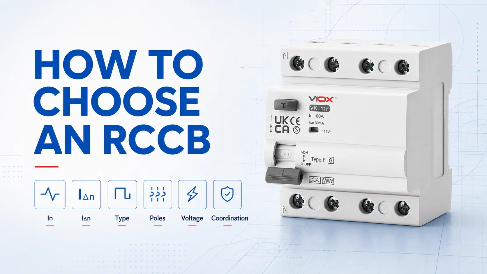
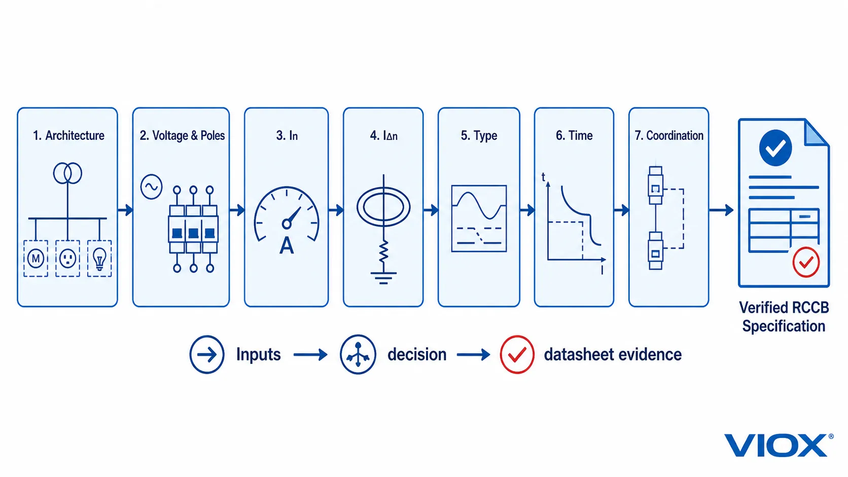
ការជ្រើសរើស Residual Current Circuit Breaker (RCCB) តម្រូវឱ្យមានច្រើនជាងការជ្រើសរើស 40A ឬ 63A, និងច្រើនជាងការជ្រើសរើស 30 mA. ។ សញ្ញាសម្គាល់ទាំងនោះពិពណ៌នាអំពីលក្ខណៈផ្សេងៗគ្នា។ លក្ខណៈបច្ចេកទេសពេញលេញនៃ RCCB ត្រូវតែបញ្ជាក់ពី៖
- ស្ថាបត្យកម្មការពារ៖ RCCB ដែលមាន MCB ឬហ្វុយស៊ីបដាច់ដោយឡែក ឬប្រើ RCBO ជំនួសវិញ;
- វាយតម្លៃបច្ចុប្បន្ន ក្នុង;
- ចរន្តប្រតិបត្តិការសេសសល់ដែលបានកំណត់ (Rated residual operating current) IΔn;
- ប្រភេទចរន្តសំណល់៖ AC, A, F, ឬ B;
- ការរៀបចំបង្គោល;
- វ៉ុល និងប្រេកង់ដែលបានកំណត់ (Rated voltage and frequency);
- ប្រតិបត្តិការភ្លាមៗ ឬប្រតិបត្តិការជ្រើសរើស/ពន្យារពេល; និង
- ការសម្របសម្រួលដែលបានចងក្រងជាឯកសារជាមួយឧបករណ៍ការពារចរន្តលើសដែលពាក់ព័ន្ធ។.
ចាប់ផ្តើមជាមួយសៀគ្វី និងមុខងារការពារដែលត្រូវការ។ បញ្ចប់ដោយការបញ្ជាក់ជាលាយលក្ខណ៍អក្សរដែលអាចពិនិត្យផ្ទៀងផ្ទាត់ជាមួយសន្លឹកទិន្នន័យ តារាងសម្របសម្រួល វិញ្ញាបនបត្រ និងច្បាប់ដំឡើងជាក់លាក់។ កុំចាប់ផ្តើមដោយជ្រើសរើសម៉ូដែល RCCB ណាមួយដែលមាននៅលើធ្នើ។.
សន្លឹកកិច្ចការជ្រើសរើស RCCB: ធាតុចូលសម្រាប់ការបញ្ជាក់
ប្រើតារាងនេះមុនពេលប្រៀបធៀបផលិតផល។ ធាតុចូលដែលទទេមានន័យថា RCCB មិនទាន់រួចរាល់សម្រាប់ការបញ្ជាក់នោះទេ។.
| ទិន្នន័យបញ្ចូលដែលត្រូវការ | ការសម្រេចចិត្តជ្រើសរើស | លទ្ធផលនៃលក្ខណៈបច្ចេកទេស | ភស្តុតាងសម្រាប់ផ្ទៀងផ្ទាត់ |
|---|---|---|---|
| ស្ថាបត្យកម្មការពារដែលតម្រូវ | RCCB បូករួមនឹង MCB/ហ្វុយស៊ីប ឬ RCBO | ក្រុមឧបករណ៍ និងការរៀបចំការការពារ | ការរចនាសៀគ្វី ស្ថាបត្យកម្មបន្ទះចែកចាយ និងវិធានដែលពាក់ព័ន្ធ |
| ប្រព័ន្ធផ្គត់ផ្គង់ និងខ្សែមានចរន្ត | វ៉ុល ប្រេកង់ និងចំនួនប៉ូល | Ue, ប្រេកង់, 2P/4P ឬការរៀបចំផ្សេងទៀតដែលបានផ្ទៀងផ្ទាត់ | ដ្យាក្រាមខ្សែតែមួយ ដ្យាក្រាមឧបករណ៍ និងការណែនាំអំពីផលិតផល |
| ចរន្តរចនា និងកាតព្វកិច្ច | កម្រិតសមត្ថភាពផ្ទុកចរន្តដែលត្រូវការ | ក្នុង | តារាងបន្ទុក ការវាយតម្លៃភាពចម្រុះ និងលក្ខខណ្ឌជុំវិញ និងការដាក់ជាក្រុម |
| គោលបំណងការពារ និងទីតាំងដំឡើង | ភាពប្រែប្រួលចរន្តលេច | IΔn | វិធានការដំឡើង ការរចនាប្រព័ន្ធដី និងមុខងារសៀគ្វី |
| ឧបករណ៍ដែលបានតភ្ជាប់ និងទម្រង់រលកចរន្តសំណល់ដែលអាចកើតមាន | ប្រភេទ RCCB | ប្រភេទ AC, A, F ឬ B | សៀវភៅណែនាំឧបករណ៍, ថូប៉ូឡូជីនៃបន្ទុក, ច្បាប់ដែលពាក់ព័ន្ធ |
| ការការពារចរន្តសំណល់ផ្នែកខាងលើ/ខាងក្រោម | លក្ខណៈពេលវេលា និងការជ្រើសរើស | ភ្លាមៗ ឬបែបជ្រើសរើស/ពន្យារពេល | ទិន្នន័យជ្រើសរើសរបស់អ្នកផលិត និងការសិក្សាអំពីការការពារ |
| លក្ខខណ្ឌនៃកំហុសដែលរំពឹងទុក និង MCB/ហ្វុយស៊ីបដែលពាក់ព័ន្ធ | ការសម្របសម្រួលពេលមានការឆ្លងចរន្តខ្លី (Short-circuit) | SCPD បម្រុងដែលត្រូវការ និងភស្តុតាងនៃការវាយតម្លៃតាមលក្ខខណ្ឌ | តារាងសម្របសម្រួល RCCB–MCB/ហ្វុយស៊ីបជាក់លាក់ |
| ទីផ្សារគោលដៅ និងឯកសារគម្រោង | ស្តង់ដារ និងដំណើរការអនុម័ត | ការបោះពុម្ពស្តង់ដារដែលអាចអនុវត្តបាន វិញ្ញាបនបត្រ និងរបាយការណ៍ | ឯកសារម៉ូដែលជាក់លាក់ មិនមែនជាការសន្មតកម្រិតក្រុមផលិតផលនោះទេ |
លទ្ធផលនេះមិនទាន់ជាលេខម៉ូដែលនៅឡើយទេ។ វាគឺជាតម្រូវការដែលលេខម៉ូដែលអាចត្រូវបានត្រួតពិនិត្យធៀបនឹងវាបាន។.
ជំហានទី 1៖ បញ្ជាក់ថា RCCB គឺជាឧបករណ៍ត្រឹមត្រូវ
RCCB មួយរកឃើញចរន្តសំណល់ ប៉ុន្តែមិនរួមបញ្ចូលការការពារការផ្ទុកលើស ឬសៀគ្វីខ្លីដែលភ្ជាប់មកជាមួយនោះទេ។ IEC 61008-1:2024 គ្របដណ្តប់លើ RCCB ដែលគ្មានការការពារចរន្តលើសដែលភ្ជាប់មកជាមួយ សម្រាប់ប្រើប្រាស់ក្នុងគ្រួសារ និងការប្រើប្រាស់ស្រដៀងគ្នា ក្នុងដែនកំណត់វ៉ុល ប្រេកង់ និងចរន្តដែលបានបញ្ជាក់។.
ព្រំដែនមុខងារនោះផ្លាស់ប្តូរការសម្រេចចិត្តជ្រើសរើសដំបូង៖
| ស្ថាបត្យកម្មដែលតម្រូវ | ឧបករណ៍សម្រាប់វាយតម្លៃ | ចំណុចសំខាន់ៗ |
|---|---|---|
| ការការពារចរន្តសំណល់ដោយប្រើ MCB ឬហ្វុយស៊ីបដាច់ដោយឡែក | RCCB | RCCB និងឧបករណ៍ការពារចរន្តលើសដែលពាក់ព័ន្ធត្រូវតែសម្របសម្រួលជាការរួមបញ្ចូលគ្នា |
| ការការពារចរន្តសំណល់ ការផ្ទុកលើស និងសៀគ្វីខ្លីនៅក្នុងឧបករណ៍តែមួយ | RCBO | ឧបករណ៍នេះត្រូវតែបំពេញតាមតម្រូវការទាំងចរន្តសំណល់ និងចរន្តលើស |
| RCCB មួយការពារក្រុមសៀគ្វីដែលផ្គត់ផ្គង់ដោយ MCB | RCCB + MCBs | ពិចារណាលើការលេចធ្លាយចរន្តសរុប និងកម្រិតនៃការបាត់បង់ការផ្គត់ផ្គង់ ប្រសិនបើ RCCB ដំណើរការ |
| ការការពារឯករាជ្យ និងការផ្តាច់កំហុសសម្រាប់សៀគ្វីបញ្ចេញនីមួយៗ | ការប្រើប្រាស់ RCBO ដាច់ដោយឡែកអាចមានភាពសមស្របជាង | សៀគ្វីនីមួយៗត្រូវការលក្ខណៈបច្ចេកទេសនៃចរន្តសំណល់ និងចរន្តលើសផ្ទុកពេញលេញដោយឡែកពីគ្នា |
សម្រាប់ការថ្លឹងថ្លែងនៅកម្រិតផ្ទាំងបញ្ជា សូមប្រើមគ្គុទ្ទេសក៍ VIOX ដើម្បី RCBO បើធៀបនឹង RCCB បូករួមជាមួយ MCB. ប្រសិនបើការរចនាទាមទារឱ្យមាន RCCB សូមបន្តបំពេញវាលដែលនៅសល់ខាងក្រោម។.
ជំហានទី 2៖ កំណត់វ៉ុល ប្រេកង់ និងចំនួនប៉ូល
កត់ត្រាការរៀបចំការផ្គត់ផ្គង់ជាក់ស្តែង ជាជាងចាត់ទុកចំនួនប៉ូលជាជម្រើសតុបតែង។.
ផ្គូផ្គងវ៉ុល និងប្រេកង់ដែលបានកំណត់
វ៉ុល និងប្រេកង់ប្រតិបត្តិការដែលបានប្រកាសរបស់ RCCB ត្រូវតែគ្របដណ្តប់លើលក្ខខណ្ឌនៃសៀគ្វី។ សូមពិនិត្យមើលសន្លឹកទិន្នន័យឱ្យបានច្បាស់លាស់ រួមទាំងថាតើសៀគ្វីតេស្ត និងមុខងារដែលអាស្រ័យលើវ៉ុលណាមួយមានតម្រូវការផ្គត់ផ្គង់ដែរឬទេ។ កុំសន្និដ្ឋានពីភាពសមស្របដោយផ្អែកលើកម្រិតចរន្ត ឬទទឹងម៉ូឌុលជាក់ស្តែង។.
ផ្គូផ្គងការរៀបចំប៉ូលទៅនឹងខ្សែដែលមានចរន្តអគ្គិសនី
ខ្សែដែលមានចរន្តអគ្គិសនីទាំងអស់ដែលស្ថិតក្នុងសៀគ្វីការពារ និងតម្រូវដោយការរចនារបស់ឧបករណ៍ ត្រូវតែឆ្លងកាត់ការរៀបចំចាប់សញ្ញាចរន្តសំណល់របស់ RCCB។ ការធ្វើផែនទីបឋមទូទៅមានដូចខាងក្រោម៖
| ការរៀបចំការផ្គត់ផ្គង់ | ចំណុចចាប់ផ្តើមទូទៅ | អ្វីដែលនៅតែត្រូវការការផ្ទៀងផ្ទាត់ |
|---|---|---|
| ខ្សែដំណាក់កាលតែមួយ និងខ្សែណឺត | RCCB 2 ប៉ូល | ការរៀបចំខ្សែណឺត ការកំណត់អត្តសញ្ញាណស្ថានីយ តម្រូវការនៃការប្តូរ និងវ៉ុលកំណត់ |
| បីដំណាក់កាលជាមួយអព្យាក្រឹត | RCCB 4 ប៉ូល | លំដាប់ដំណាក់កាលក្នុងករណីពាក់ព័ន្ធ ការគ្រប់គ្រងខ្សែណឺត ដ្យាក្រាមឧបករណ៍ និងវ៉ុលកំណត់ |
| បីដំណាក់កាលដោយគ្មានខ្សែណឺត | អាស្រ័យលើផលិតផល និងប្រព័ន្ធ | ថាតើការរចនា RCCB ដែលបានជ្រើសរើសគាំទ្រការរៀបចំនេះឬទេ និងរបៀបដែលខ្សែមានចរន្តអគ្គិសនីនីមួយៗត្រូវបានត្រួតពិនិត្យ |
តារាងនេះគឺជាជំនួយក្នុងការជ្រើសរើស មិនមែនជាការណែនាំអំពីការតភ្ជាប់ខ្សែភ្លើងនោះទេ។ ការដំឡើងត្រូវតែអនុវត្តតាមដ្យាក្រាមឧបករណ៍ជាក់លាក់ និងច្បាប់ដែលពាក់ព័ន្ធ។ ដោយឡែក មគ្គុទ្ទេសក៍ការតភ្ជាប់ខ្សែភ្លើងសម្រាប់ RCCB ប្រភេទ 2-pole និង 4-pole គ្របដណ្តប់លើកិច្ចការដំឡើង បន្ទាប់ពីផលិតផលត្រូវបានជ្រើសរើសរួចរាល់។.
ជំហានទី 3៖ កំណត់ចរន្តកំណត់ In
ការសម្គាល់អំពែរនៅលើ RCCB គឺជាចរន្តកំណត់របស់វា ក្នុង៖ ជាចរន្តដែលវាត្រូវបានរចនាឡើងដើម្បីផ្ទុកក្រោមលក្ខខណ្ឌដែលបានកំណត់។ វាមិនមែនជាការកំណត់ការកាត់ផ្តាច់នៅពេលផ្ទុកលើសនោះទេ។.
RCCB ទំហំ 63A មិនរង់ចាំរហូតដល់ 63A ទើបកាត់ផ្តាច់ដូចជាឧបករណ៍ការពារចរន្តលើសនោះទេ។ MCB, ហ្វុយស៊ីប ឬឧបករណ៍ការពារផ្សេងទៀតដែលពាក់ព័ន្ធ ត្រូវតែផ្តល់ការការពារការផ្ទុកលើស និងសៀគ្វីខ្លីតាមតម្រូវការ។.
ប្រើការត្រួតពិនិត្យចំនួនបួននៅពេលកំណត់ In៖
- ចរន្តរចនា៖ កំណត់ចរន្តដែល RCCB ត្រូវបានរំពឹងថានឹងផ្ទុក ដោយផ្អែកលើតារាងសៀគ្វី និងការវាយតម្លៃភាពចម្រុះ។.
- លក្ខខណ្ឌនៃការដំឡើង៖ សូមពិនិត្យមើលការណែនាំរបស់អ្នកផលិតសម្រាប់សីតុណ្ហភាពព័ទ្ធជុំវិញ ការដាក់ជាក្រុម លក្ខខណ្ឌនៃប្រអប់ការពារ និងកត្តាផ្សេងទៀតដែលអាចប៉ះពាល់ដល់សមត្ថភាពផ្ទុកចរន្ត។.
- ការការពារចរន្តលើសដែលពាក់ព័ន្ធ៖ សូមបញ្ជាក់ថាចំណាត់ថ្នាក់ និងលក្ខណៈរបស់ MCB ឬហ្វុយស៊ីបដែលបានជ្រើសរើស អាចការពារ RCCB បានក្នុងលក្ខខណ្ឌសម្របសម្រួលដែលបានកំណត់ដោយអ្នកផលិត។.
- ការការពារខ្សែចំលង៖ សូមផ្ទៀងផ្ទាត់ការការពារខ្សែដោយឡែកពីគ្នា។ ការដំឡើង RCCB ពី 40A ទៅ 63A មិនបង្កើនសមត្ថភាពផ្ទុកចរន្តរបស់ខ្សែឡើយ ហើយក៏មិនអាចដោះស្រាយបញ្ហាការដាច់ចរន្តដោយសារចរន្តសំណល់បានដែរ។.
សូមសរសេរតម្រូវការនៃការជ្រើសរើសជាសេចក្តីថ្លែងការណ៍សម្របសម្រួល មិនមែនជាលេខដាច់ដោយឡែកនោះទេ៖
ចរន្តកំណត់ In៖ ___ A ដែលសមស្របសម្រាប់កាតព្វកិច្ចដែលបានគណនា និងបានផ្ទៀងផ្ទាត់ជាមួយ MCB/ហ្វុយស៊ីប ___ A នៅផ្នែកខាងលើ ឬដែលពាក់ព័ន្ធ ក្រោមលក្ខខណ្ឌដែលក្រុមហ៊ុនផលិតបានប្រកាស។.
ជំហានទី 4៖ ជ្រើសរើសចរន្តប្រតិបត្តិការសំណល់ដែលបានកំណត់ IΔn
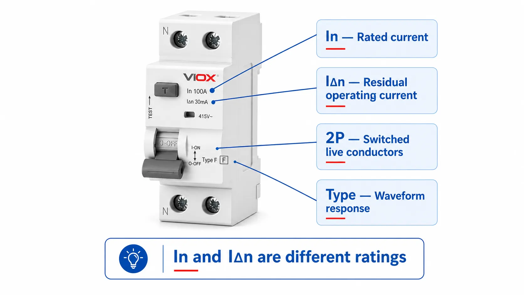
IΔn គឺជាភាពប្រែប្រួលនៃចរន្តសំណល់ ដែលជាធម្មតាត្រូវបានបង្ហាញជាមីលីអំពែរ។ វាឆ្លើយតបទៅនឹងសំណួរដែលខុសពី In។.
| សញ្ញាសម្គាល់ | អ្វីដែលវាពិពណ៌នា | ឧទាហរណ៍ធម្មតា |
|---|---|---|
| ក្នុង | កម្រិតផ្ទុកចរន្ត | 25A, 40A, 63A, 100A |
| IΔn | ចរន្តប្រតិបត្តិការសេសសល់ដែលបានកំណត់ (Rated residual operating current) | 30mA, 100mA, 300mA |
ជ្រើសរើស IΔn ដោយផ្អែកលើគោលបំណងការពារដែលត្រូវការ ទីតាំងសៀគ្វី ការរៀបចំប្រព័ន្ធដី ការលេចធ្លាយចរន្តធម្មតា តម្រូវការនៃការផ្តាច់ចរន្ត និងច្បាប់ក្នុងស្រុកដែលពាក់ព័ន្ធ។ នៅក្នុងការដំឡើងផ្អែកលើស្តង់ដារ IEC ជាច្រើន ឧបករណ៍ដែលមានកម្រិតមិនលើសពី 30mA ត្រូវបានផ្សារភ្ជាប់ជាមួយនឹងការការពារបន្ថែមសម្រាប់សៀគ្វីដែលបានកំណត់។ តម្លៃខ្ពស់ជាងនេះអាចបម្រើដល់ការការពារកំហុស ការការពារនៅផ្នែកខាងលើ ការការពារបែបជ្រើសរើស ឬមុខងារការពារហានិភ័យអគ្គិភ័យ ក្នុងករណីដែលការរចនា និងច្បាប់ដែលពាក់ព័ន្ធអនុញ្ញាត។.
កុំប្រើ IΔn ដែលខ្ពស់ជាងនេះគ្រាន់តែដើម្បីលាក់បាំងការដាច់ចរន្តដែលមិនចង់បាន ហើយកុំកំណត់តម្លៃតែមួយសម្រាប់ប្រភេទអគារទាំងមូល។ សម្រាប់ដំណើរការសម្រេចចិត្តពេញលេញ សូមប្រើ មគ្គុទ្ទេសក៍ភាពប្រែប្រួលរបស់ RCCB កម្រិត 30mA ទល់នឹង 100mA ទល់នឹង 300mA.
កត់ត្រាលទ្ធផលជាផ្នែកបញ្ជាក់មួយ៖
ចរន្តប្រតិបត្តិការសំណល់ដែលបានកំណត់ IΔn៖ ___ mA ដែលត្រូវបានជ្រើសរើសសម្រាប់គោលបំណងការពារ និងទីតាំងដំឡើងដែលមានចែងក្នុងឯកសារ។.
ជំហានទី 5៖ ជ្រើសរើសប្រភេទ AC, A, F ឬ B
ប្រភេទ RCCB ពិពណ៌នាអំពីទម្រង់រលកនៃចរន្តសំណល់ដែលឧបករណ៍ត្រូវបានរចនាឡើងដើម្បីចាប់សញ្ញា។ វាមិនពិពណ៌នាអំពីខ្សែកោងនៃការកាត់ផ្តាច់របស់ MCB នោះទេ ហើយវាមិនអាចជ្រើសរើសបានដោយផ្អែកលើស្លាកសញ្ញានៅនឹងកន្លែងតែមួយមុខបានឡើយ។.
ចាប់ផ្តើមជាមួយឧបករណ៍ដែលបានតភ្ជាប់៖
- តើវាមានឧបករណ៍កែតម្រូវ (rectifiers) ឧបករណ៍ផ្គត់ផ្គង់ថាមពលអេឡិចត្រូនិក ឧបករណ៍បំប្លែងចរន្ត (inverters) ឧបករណ៍បើកបរ (drives) ឬតំណភ្ជាប់ DC ដែរឬទេ?
- តើទម្រង់រលកនៃចរន្តសំណល់អ្វីខ្លះដែលវាអាចបង្កើតបានក្នុងលក្ខខណ្ឌធម្មតា និងលក្ខខណ្ឌមានកំហុស?
- តើក្រុមហ៊ុនផលិតឧបករណ៍បានបញ្ជាក់ពីប្រភេទ RCD នៅផ្នែកខាងលើ (upstream) ឬការរៀបចំសម្រាប់ចាប់សញ្ញា DC ដាច់ដោយឡែកដែរឬទេ?
- តើវិធាននៃការដំឡើងដែលអនុវត្តបានមានការកំណត់លើប្រភេទ AC ឬតម្រូវឱ្យមានសមត្ថភាពជាក់លាក់ណាមួយដែរឬទេ?
សូមប្រើផែនទីព្រំដែននេះសម្រាប់ការត្រួតពិនិត្យបឋម៖
| ប្រភេទ RCCB | ព្រំដែនរលកសញ្ញាបឋម | ការប្រុងប្រយ័ត្នក្នុងការជ្រើសរើស |
|---|---|---|
| វាយ AC | ចរន្តលេចធ្លាយឆ្លាស់រលកស៊ីនុស | កុំប្រើវាគ្រាន់តែដោយសារវាជាជម្រើសដែលមានតម្លៃទាបបំផុត សូមផ្ទៀងផ្ទាត់ថាបន្ទុក និងវិធានអនុញ្ញាតឱ្យប្រើវាបាន |
| ប្រភេទ A | ចរន្តសំណល់ AC បូករួមនឹងចរន្ត DC ដែលមានចង្វាក់ ស្ថិតក្នុងនិយមន័យផលិតផលដែលអនុវត្តបាន | អាចនៅតែមិនសមស្របក្នុងករណីដែលចរន្ត DC រលូន ឬចរន្តសំណល់ស្មុគស្មាញផ្សេងទៀតអាចកើតឡើង |
| ប្រភេទ F | សមត្ថភាពបន្ថែមសម្រាប់ចរន្តសំណល់ចម្រុះដែលបានបញ្ជាក់ ដែលទាក់ទងនឹងបន្ទុកឧបករណ៍បំប្លែងប្រេកង់ដំណាក់កាលតែមួយមួយចំនួន | មិនមែនជាឧបករណ៍ជំនួសជាសកលសម្រាប់ប្រភេទ B នោះទេ |
| ប្រភេទ ខ | រួមបញ្ចូលសមត្ថភាពសម្រាប់ DC រលូន និងសមាសភាគប្រេកង់បន្ថែមនៅក្នុងនិយមន័យផលិតផលដែលអាចអនុវត្តបាន | កុំចាត់ទុកវាជាការដំឡើងកំណែជាសកល។ ការណែនាំអំពីឧបករណ៍ ការសម្របសម្រួលប្រព័ន្ធ ច្បាប់ជាតិ និងការរៀបចំរកឃើញ DC ដាច់ដោយឡែកណាមួយ នៅតែជាកត្តាកំណត់ជម្រើសចុងក្រោយ |
IEC 62423 កំណត់តម្រូវការ និងការធ្វើតេស្តបន្ថែមសម្រាប់ RCD ប្រភេទ F និងប្រភេទ B ហើយត្រូវបានប្រើប្រាស់រួមគ្នាជាមួយស្តង់ដារផលិតផល RCCB ឬ RCBO ដែលពាក់ព័ន្ធ។ ឯកសារម៉ូដែលជាក់លាក់ត្រូវតែបញ្ជាក់ពីប្រភេទ និងផ្លូវស្តង់ដារដែលអាចអនុវត្តបាន។.
កត់ត្រាភស្តុតាង មិនមែនត្រឹមតែអក្សរប៉ុណ្ណោះទេ៖
ប្រភេទចរន្តសំណល់៖ ប្រភេទ ___ ដោយផ្អែកលើសៀវភៅណែនាំឧបករណ៍ដែលបានតភ្ជាប់ រូបរាងរលកចរន្តសំណល់ដែលរំពឹងទុក និងតម្រូវការដំឡើងដែលអាចអនុវត្តបាន។.
ជំហានទី 6៖ ជ្រើសរើសលក្ខណៈពេលវេលា
ប្រសិនបើឧបករណ៍ការពារចរន្តសំណល់មួយត្រូវបានដំឡើងនៅខាងលើឧបករណ៍មួយទៀត តម្លៃ IΔn ដែលខុសគ្នាតែមួយមុខមិនអាចបញ្ជាក់ពីភាពជ្រើសរើសបានទេ។ ឧបករណ៍នៅខាងលើ និងខាងក្រោមត្រូវតែសម្របសម្រួលដោយទាំងកម្រិតកំណត់ចរន្តសំណល់ និងឥរិយាបថពេលវេលាប្រតិបត្តិការ ដោយមានការគាំទ្រពីទិន្នន័យរបស់អ្នកផលិត និងការរចនាការដំឡើង។.
សូមបញ្ជាក់ថាតើឧបករណ៍នេះជា៖
- ប្រភេទប្រតិបត្តិការភ្លាមៗ, ដែលមុខងារការពារដែលត្រូវការតម្រូវឱ្យមានប្រតិបត្តិការរហ័ស ឬ
- ប្រភេទជ្រើសរើស/ពន្យារពេល, ដែលឧបករណ៍នៅខាងលើត្រូវបានបម្រុងទុកសម្រាប់សម្របសម្រួលជាមួយឧបករណ៍ការពារនៅខាងក្រោម ហើយកម្មវិធីអនុញ្ញាតឱ្យមានការពន្យារពេលនោះ។.
ឧបករណ៍ប្រភេទជ្រើសរើសមិនត្រូវជំនួសមុខងារការពារបន្ថែមដែលត្រូវការឱ្យមានល្បឿនលឿននោះទេ គ្រាន់តែដើម្បីកែលម្អភាពបន្ត។ សូមកត់ត្រាលក្ខណៈពេលវេលា និងភស្តុតាងនៃការសម្របសម្រួលរួមគ្នា៖
លក្ខណៈពេលវេលា៖ ___; ការសម្របសម្រួលត្រូវផ្ទៀងផ្ទាត់ធៀបនឹងឯកសារយោងឧបករណ៍នៅខាងលើ/ខាងក្រោម ___ និងទិន្នន័យជ្រើសរើសរបស់អ្នកផលិត ___ ។ .
ជំហានទី 7៖ ផ្ទៀងផ្ទាត់ការសម្របសម្រួលសៀគ្វីខ្លី និងចរន្តលើស
ជំហាននេះគឺជាអ្វីដែលប្រែក្លាយបញ្ជីកម្រិតកំណត់របស់ RCCB ទៅជាលក្ខណៈបច្ចេកទេសដែលអាចការពារបាន។.
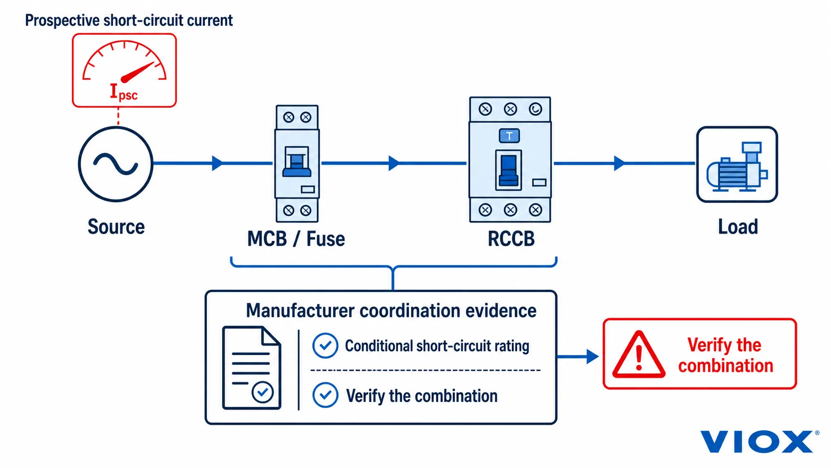
ដោយសារ RCCB មិនមានការការពារចរន្តលើសរួមបញ្ចូលក្នុងខ្លួន ឥរិយាបថរបស់វានៅក្រោមលក្ខខណ្ឌសៀគ្វីខ្លីគឺអាស្រ័យលើការរៀបចំដែលបានប្រកាសជាមួយឧបករណ៍ការពារសៀគ្វីខ្លីដែលពាក់ព័ន្ធ ឬឧបករណ៍បម្រុង។ ឯកសារផលិតផលអាចបញ្ជាក់ពីចរន្តសៀគ្វីខ្លីតាមលក្ខខណ្ឌ និងកំណត់ហ្វុយហ្ស៊ីប MCB ឬ SCPD ផ្សេងទៀតដែលតម្រូវ។.
មុនពេលទទួលយកម៉ូដែលណាមួយ សូមផ្ទៀងផ្ទាត់៖
- ចរន្តសៀគ្វីខ្លីដែលរំពឹងទុកនៅចំណុចដំឡើង;
- ឯកសារយោង RCCB ជាក់លាក់ មិនមែនត្រឹមតែក្រុមផលិតផលប៉ុណ្ណោះទេ;
- ប្រភេទ និងកម្រិតកំណត់របស់ MCB ឬហ្វុយហ្ស៊ីបដែលពាក់ព័ន្ធជាក់លាក់;
- តារាងការពារសៀគ្វីខ្លីតាមលក្ខខណ្ឌ ឬតារាងការពារបម្រុងរបស់អ្នកផលិត;
- កម្រិតអតិបរមានៃឧបករណ៍ការពារនៅផ្នែកខាងលើ (upstream) ណាមួយ;
- ការសម្របសម្រួលការផ្ទុកលើស និងការការពារខ្សែចម្លង;
- ការជ្រើសរើសចរន្តសំណល់នៅផ្នែកខាងលើ/ខាងក្រោម តាមដែលអាចអនុវត្តបាន; និង
- វ៉ុលកំណត់ ហ្វ្រេកង់ ចំនួនប៉ូល និងការរៀបចំស្ថានីយសម្រាប់ម៉ូដែលដូចគ្នា។.
កុំសន្មតថាការបង្ហាញតម្លៃសៀគ្វីខ្លីដ៏លេចធ្លោនៅលើខិត្តប័ណ្ណ មានន័យថា RCCB អាចកាត់ផ្តាច់ចរន្តនោះដោយឯករាជ្យ។ សូមអានឱ្យយល់ពីអត្ថន័យនៃតម្លៃនោះ និងឧបករណ៍ការពារបម្រុងអ្វីដែលតម្រូវឱ្យមាន។.
សម្រាប់ព្រំដែនរវាងតម្រូវការផលិតផល និងការរចនាការដំឡើង សូមមើលការពន្យល់របស់ VIOX អំពី តម្រូវការស្តង់ដារ IEC 61008-1 សម្រាប់ឧបករណ៍ RCCB. IEC 61008-1:2024 ផ្តល់នូវវិធានទូទៅ; ចំណែក IEC 61008 ផ្នែកទី 2 ដែលអាចអនុវត្តបាន គឺអាស្រ័យលើចំណាត់ថ្នាក់ និងការរចនារបស់ RCCB។.
ឧទាហរណ៍អនុវត្ត៖ ពីការបញ្ចូលសៀគ្វី ទៅជាតម្រូវការ RCCB
ឧទាហរណ៍ខាងក្រោមនេះគឺជាការសន្មត។ វាបង្ហាញពីតក្កវិជ្ជានៃឯកសារ មិនមែនជាការណែនាំផលិតផលជាសកលនោះទេ។.
ទិន្នន័យបញ្ចូលនៃគម្រោងដែលបានកត់ត្រា
- សៀគ្វីហ្វាសតែមួយ 230V, 50Hz ដែលមានខ្សែឡាញ (L) និងខ្សែណឺត (N)។;
- ចរន្តរចនាដែលបានគណនា៖ 32A។;
- MCB ទំហំ 32A ដាច់ដោយឡែកមួយត្រូវបានរក្សាទុកសម្រាប់ការការពារចរន្តលើស។;
- ការរចនាការដំឡើងដែលអនុវត្តបានតម្រូវឱ្យមានការការពារបន្ថែម 30mA។;
- ឯកសារនៃឧបករណ៍ដែលបានតភ្ជាប់តម្រូវឱ្យមានការការពារចរន្តសំណល់ប្រភេទ Type A។;
- មិនមានឧបករណ៍ការពារចរន្តសំណល់នៅផ្នែកខាងលើ (upstream) ដែលតម្រូវឱ្យមានការកំណត់ពេលនោះទេ។;
- ចរន្តសៀគ្វីខ្លីដែលរំពឹងទុកត្រូវបានគណនាហើយ ប៉ុន្តែត្រូវតែពិនិត្យផ្ទៀងផ្ទាត់ជាមួយការរួមបញ្ចូលគ្នារវាង RCCB និង MCB ជាក់លាក់; និង
- ឯកសារ និងវិញ្ញាបនបត្រសម្រាប់ទីផ្សារគោលដៅត្រូវតែផ្តល់ជូនសម្រាប់ម៉ូដែលជាក់លាក់នោះ។.
លក្ខណៈបច្ចេកទេសបឋមដែលទទួលបាន
| វិស័យ | លទ្ធផលសម្មតិកម្ម |
|---|---|
| ស្ថាបត្យកម្ម | RCCB ជាមួយ MCB ទំហំ 32A ដាច់ដោយឡែក |
| បង្គោល | 2P អាស្រ័យលើដ្យាក្រាមខ្សែភ្លើងរបស់ផលិតផល និងតម្រូវការខ្សែណឺត (neutral) |
| វ៉ុល/ប្រេកង់ដែលបានកំណត់ | សមស្របសម្រាប់លក្ខខណ្ឌសៀគ្វី 230V, 50Hz |
| ក្នុង | អប្បបរមា 40A ក្នុងឧទាហរណ៍នេះ ដោយអាស្រ័យលើការបញ្ជាក់ពីក្រុមហ៊ុនផលិតជាមួយនឹង MCB 32A ជាក់លាក់ និងលក្ខខណ្ឌនៃការដំឡើង។ |
| IΔn | 30 mA |
| ប្រភេទ | ប្រភេទ A |
| លក្ខណៈពេលវេលា | ភ្លាមៗ |
| ភស្តុតាងនៃសៀគ្វីខ្លី | តារាងក្រុមហ៊ុនផលិតដែលបញ្ជាក់ពីការរួមបញ្ចូលគ្នារវាង RCCB + MCB 32A ជាក់លាក់ សម្រាប់ចរន្តរំពឹងទុកដែលបានគណនា។ |
| ឯកសារ | សន្លឹកទិន្នន័យ វិញ្ញាបនបត្រ/របាយការណ៍ដែលអាចអនុវត្តបាន ដ្យាក្រាមខ្សែភ្លើង ទិន្នន័យសម្របសម្រួល និងការកំណត់អត្តសញ្ញាណម៉ូដែល។ |
ការផ្លាស់ប្តូរធាតុចូលសំខាន់ៗណាមួយអាចផ្លាស់ប្តូរលទ្ធផល។ បន្ទុកបីហ្វាសផ្លាស់ប្តូរការពិនិត្យលើប៉ូល និងវ៉ុល។ ឧបករណ៍អេឡិចត្រូនិកថាមពលអាចផ្លាស់ប្តូរប្រភេទ RCCB ដែលត្រូវការ។ ឧបករណ៍ការពារចរន្តសំណល់នៅផ្នែកខាងលើតម្រូវឱ្យមានការសិក្សាអំពីភាពជ្រើសរើស។ ចរន្តកំហុសរំពឹងទុកផ្សេងគ្នាអាចធ្វើឱ្យការរួមបញ្ចូលគ្នានៃការការពារបម្រុងដែលបានស្នើឡើងមិនមានសុពលភាព។.
គំរូបញ្ជាក់លក្ខណៈបច្ចេកទេស RCCB ចុងក្រោយ
បំពេញប្លុកនេះឱ្យបានពេញលេញ មុនពេលស្នើសុំការផ្គូផ្គងផលិតផល ឬសម្រង់តម្លៃ៖
ឯកសារយោងគម្រោង / សៀគ្វី៖
ទីផ្សារគោលដៅ៖
បន្ទុកដែលបានការពារ និងទីតាំងសៀគ្វី៖

ស្ថាបត្យកម្មការពារ៖ RCCB + [MCB / ហ្វុយស៊ីប / SCPD ផ្សេងទៀត]
ចរន្តកំណត់ In៖ ___ A
ចរន្តប្រតិបត្តិការសំណល់កំណត់ IΔn៖ ___ mA
ប្រភេទចរន្តសំណល់៖ AC / A / F / B / ប្រភេទផ្សេងទៀតដែលបានផ្ទៀងផ្ទាត់
ប៉ូល៖ ___
វ៉ុលកំណត់៖ ___ V AC
ប្រេកង់កំណត់៖ ___ Hz
លក្ខណៈពេលវេលា៖ ភ្លាមៗ / ជ្រើសរើស / ថ្នាក់ផ្សេងទៀតដែលបានផ្ទៀងផ្ទាត់

ឧបករណ៍ការពារចរន្តលើសដែលពាក់ព័ន្ធ៖
ក្រុមហ៊ុនផលិត / ស៊េរី / ឯកសារយោង៖ ___
កម្រិត និងលក្ខណៈ៖ ___

ចរន្តសៀគ្វីខ្លីរំពឹងទុកនៅចំណុចដំឡើង៖ ___
ភស្តុតាងនៃសៀគ្វីខ្លីតាមលក្ខខណ្ឌ / ការការពារបម្រុងដែលត្រូវការ៖ ___
ភស្តុតាងនៃភាពជ្រើសរើសផ្នែកខាងលើ/ខាងក្រោមដែលត្រូវការ៖ ___

ស្តង់ដារផលិតផលដែលអាចអនុវត្តបាន និងការបោះពុម្ពផ្សាយ៖ ___
ច្បាប់ដំឡើងដែលអាចអនុវត្តបាន៖ ___
ឯកសារយោងការណែនាំឧបករណ៍ដែលបានតភ្ជាប់៖ ___
វិញ្ញាបនបត្រ របាយការណ៍ និងគំនូរដែលត្រូវការ៖ ___
បរិមាណ និងតម្រូវការដឹកជញ្ជូន/ឯកសារ៖ ___
មានតែបន្ទាប់ពីបំពេញវាលទាំងនេះរួចរាល់ប៉ុណ្ណោះ ទើបក្រុមការងារគម្រោងគួរធ្វើការប្រៀបធៀប ជួរផលិតផល VIOX RCCB. ។ ប្រឡោះទទេនៅក្នុងសេចក្តីសង្ខេបផលិតផលមិនមែនជាភស្តុតាងបញ្ជាក់ថាការកំណត់កម្រិតមាន ឬមិនមាននោះទេ សូមបើកឯកសារម៉ូដែលជាក់លាក់ ឬស្នើសុំការបញ្ជាក់។.
បញ្ជីត្រួតពិនិត្យការផ្ទៀងផ្ទាត់សន្លឹកទិន្នន័យ និង RFQ
មុនពេលអនុម័ត RCCB ដែលបានជ្រើសរើស សូមបញ្ជាក់ថាចំណុចទាំងអស់ខាងក្រោមនេះយោងទៅលើម៉ូដែលតែមួយដូចគ្នា៖
សម្រាប់ការពិនិត្យមើលម៉ូដែល សូមផ្ញើលក្ខណៈបច្ចេកទេសដែលបានបំពេញ ដ្យាក្រាមខ្សែតែមួយ ទីផ្សារគោលដៅ បរិមាណ និងឯកសារដែលត្រូវការទៅកាន់ [email protected]. បន្ទាប់មក VIOX អាចកំណត់អត្តសញ្ញាណស៊េរី RCCB ដែលបានបោះពុម្ពផ្សាយជិតបំផុតសម្រាប់ការផ្ទៀងផ្ទាត់ ដោយមិនចាំបាច់ជំនួសតម្លៃអំពែរ ឬមីលីអំពែរទូទៅសម្រាប់ការរចនាគម្រោងនោះទេ។.
សំណួរសម្រាប់ការជ្រើសរើសដោយផ្តោតសំខាន់
តើ RCCB ទំហំ 63A 30mA អាចជំនួស RCCB ទំហំ 40A 30mA បានដែរឬទេ?
មិនអាចកំណត់បានដោយផ្អែកលើសញ្ញាសម្គាល់ទាំងពីរនោះតែឯងទេ។ ឧបករណ៍ទាំងពីរអាចមាន IΔn ដូចគ្នា ប៉ុន្តែការជំនួសត្រូវតែផ្គូផ្គងនឹងវ៉ុល, ប្រេកង់, ចំនួនប៉ូល, ប្រភេទ RCCB, លក្ខណៈពេលវេលា, ការរៀបចំស្ថានីយ, ស្តង់ដារផលិតផល និងការសម្របសម្រួលដែលបានបញ្ជាក់ជាមួយឧបករណ៍ការពារការផ្ទុកលើសចរន្តដែលពាក់ព័ន្ធ។.
តើ 30mA មានន័យថា RCCB ត្រូវបានកំណត់កម្រិតសម្រាប់ផ្ទុកបន្ទុក 30A មែនទេ?
ទេ 30mA ជាធម្មតាសំដៅលើ IΔn ដែលជាចរន្តប្រតិបត្តិការសំណល់ដែលបានកំណត់។ សមត្ថភាពផ្ទុកបន្ទុកត្រូវបានកំណត់ដោយឡែកដោយ In ដូចជា 40A ឬ 63A ជាដើម។.
តើកម្រិតចរន្តរបស់ RCCB គួរតែខ្ពស់ជាងកម្រិតរបស់ MCB ដែរឬទេ?
កុំអនុវត្តច្បាប់ដាច់ដោយឡែកមួយដោយគ្មានឯកសារផលិតផល។ RCCB ត្រូវតែអាចទ្រាំទ្រនឹងកាតព្វកិច្ចនៃការរចនា និងត្រូវបានការពារដោយឧបករណ៍ការពារការផ្ទុកលើសចរន្តដែលពាក់ព័ន្ធ ស្របតាមលក្ខខណ្ឌសម្របសម្រួលដែលក្រុមហ៊ុនផលិតបានប្រកាស។ សូមផ្ទៀងផ្ទាត់ការរួមបញ្ចូលគ្នារវាង RCCB–MCB ឬ RCCB–ហ្វុយស៊ីបឱ្យបានត្រឹមត្រូវ។.
តើ RCCB បួនប៉ូលត្រូវបានប្រើសម្រាប់រាល់សៀគ្វីបីហ្វាសជានិច្ចឬ?
RCCB បួនប៉ូលគឺជាចំណុចចាប់ផ្តើមទូទៅសម្រាប់ប្រព័ន្ធបីហ្វាសដែលមានខ្សែណឺត ប៉ុន្តែការរៀបចំចុងក្រោយគឺអាស្រ័យលើខ្សែសៀគ្វី តម្រូវការខ្សែណឺត ការរចនាឧបករណ៍ ប្រព័ន្ធផ្គត់ផ្គង់ និងបទប្បញ្ញត្តិដែលពាក់ព័ន្ធ។ សូមផ្ទៀងផ្ទាត់ដ្យាក្រាមជាក់លាក់ជំនួសឱ្យការជ្រើសរើសចំនួនប៉ូលដោយផ្អែកលើឃ្លាថា “បីហ្វាស” តែមួយមុខ។.