
In modern electrical systems, short-circuit faults can release devastating amounts of energy in milliseconds. A prospective fault current of 50,000 amperes generates magnetic forces powerful enough to bend busbars, thermal energy intense enough to vaporize copper conductors, and arc flash hazards that endanger personnel. Yet most of this destruction is preventable.
Current limiting circuit breakers represent a fundamental advancement in circuit protection technology. Unlike conventional breakers that interrupt faults at the natural zero crossing of the AC waveform, current-limiting breakers act within milliseconds to choke off the fault current before it reaches its destructive peak. This rapid intervention dramatically reduces the mechanical and thermal stress on electrical equipment, protects sensitive electronics from damage, and significantly mitigates arc flash hazards.
For electrical engineers designing distribution systems, panel builders selecting protection devices, and facility managers responsible for critical infrastructure, understanding current-limiting technology is essential. This guide explains how current-limiting circuit breakers work, the key specifications that define their performance, and when this technology delivers critical benefits over standard circuit protection.
What is a Current Limiting Circuit Breaker?
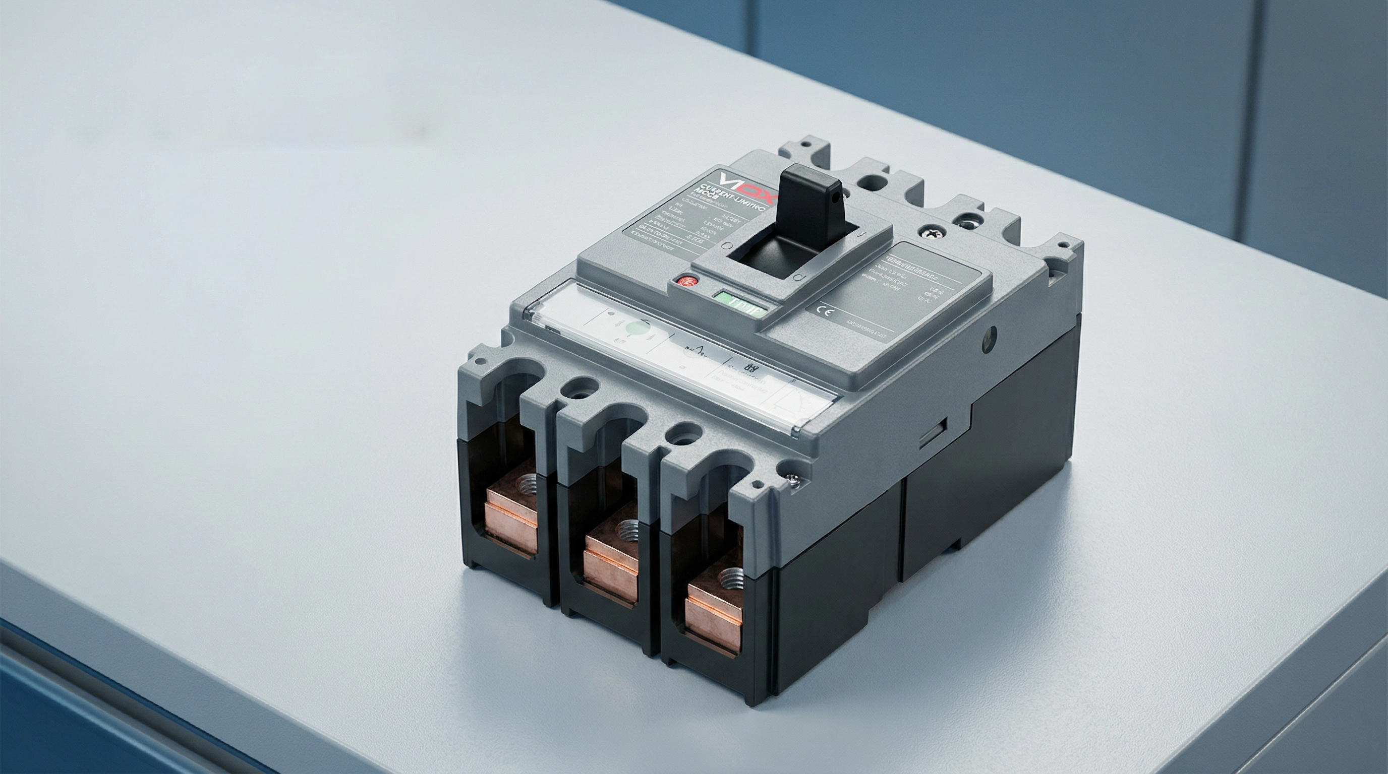
A current limiting circuit breaker is a protective device engineered to interrupt a short-circuit current before it reaches its maximum prospective peak value. This capability distinguishes it from conventional circuit breakers, which typically allow the fault current to reach its full peak before interrupting at a natural zero crossing.
When a short circuit occurs in an electrical system, the current begins rising at an extremely high rate—potentially reaching tens of thousands of amperes within milliseconds. A standard circuit breaker senses this fault condition and initiates its trip mechanism, but the interruption process takes time. During this brief interval, the fault current may reach its full prospective peak, releasing tremendous energy that stresses conductors, busbars, and downstream equipment.
Current limiting circuit breakers, by contrast, act with extraordinary speed. According to UL 489 (the North American standard for molded case circuit breakers), a circuit breaker qualifies as “current limiting” if it clears the fault in less than half a cycle—typically under 10 milliseconds. This rapid response introduces a high arc voltage that opposes the system voltage, effectively choking off the current flow and forcing the peak let-through current to a much lower value than the prospective fault current.
The result is dramatic: while a prospective fault current might be 50,000 amperes RMS symmetrical, a current-limiting breaker might limit the actual peak current to 15,000 amperes or less. This reduction in peak current and total fault energy protects downstream equipment from mechanical forces, thermal damage, and arc flash hazards that would otherwise occur.
How Current Limiting Circuit Breakers Work
The current-limiting capability of these circuit breakers results from a carefully engineered combination of mechanical design, electromagnetic physics, and arc management. The process unfolds in milliseconds through several coordinated mechanisms.
Electrodynamic Contact Separation
The first critical element is ultra-fast contact separation. When a high fault current flows through the breaker’s contacts, the enormous magnetic fields generated by this current create powerful electrodynamic forces. Current-limiting breakers are designed with contact configurations that harness these forces to assist separation—the contacts are arranged so the magnetic field creates a repulsive force that literally blows the contacts apart.
This “electrodynamic repulsion” means that higher fault currents actually accelerate contact separation. The breaker doesn’t rely solely on the mechanical force of the trip mechanism; the fault current itself contributes energy to open the contacts faster. This ensures extremely rapid contact separation—often within 1-2 milliseconds of fault initiation.
Arc Formation and Elongation
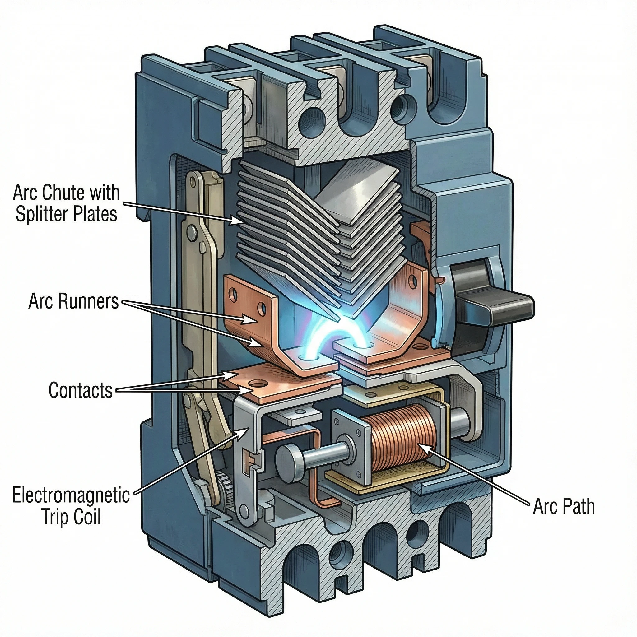
As the contacts separate at high speed, an electrical arc forms in the gap. Rather than being a problem to suppress, this arc becomes the primary tool for current limitation. The breaker’s internal geometry is designed to force this arc to move rapidly away from the contacts and into a specially designed arc chamber called an arc chute.
Magnetic fields generated by the current flow and the physical shape of the arc runners guide the arc upward into the arc chute. As the arc moves and stretches, its length increases dramatically. A longer arc requires higher voltage to sustain it, and this arc voltage opposes the system voltage driving the fault current.
Arc Commutation and Splitting
The arc chute contains a series of metal plates arranged in a specific configuration (often V-shaped), called arc splitters or arc dividers. As the arc is driven into the chute, it contacts these plates and “commutates”—transferring from the main arc path to the splitter plates.
This process effectively splits the single high-energy arc into multiple smaller arcs in series. Each small arc develops its own voltage drop. If the arc chute contains, for example, 20 splitter plates, the total arc voltage can reach many times the system voltage. When the cumulative arc voltage exceeds the system voltage, the current is forced to decrease rapidly.
Arc Cooling and Extinction
The metal splitter plates also serve as heat sinks, rapidly cooling the arcs. The plates increase the arc’s surface area and conduct heat away. Combined with surrounding air or arc-quenching gases, this cooling reduces the arc’s conductivity.
The interplay of high arc voltage (opposing current flow) and arc cooling (reducing conductivity) forces the current toward zero. The breaker extinguishes the arc and clears the fault—all within a fraction of a cycle, before the fault current reaches its prospective peak.
This entire sequence—from fault detection through contact separation, arc elongation, splitting, and extinction—occurs in under 10 milliseconds. The current is interrupted not at a natural zero crossing but forcibly, by creating conditions where the arc cannot be sustained.
Key Technical Specifications
Understanding current-limiting performance requires familiarity with three critical specifications that define how effectively a breaker limits fault current and protects downstream equipment.
Let-Through Current (Ip)
នេះ។ let-through current (Ip) is the actual peak current that flows through the breaker during a fault, measured in amperes. This value represents the breaker’s current-limiting effectiveness: a lower Ip indicates better current limitation.
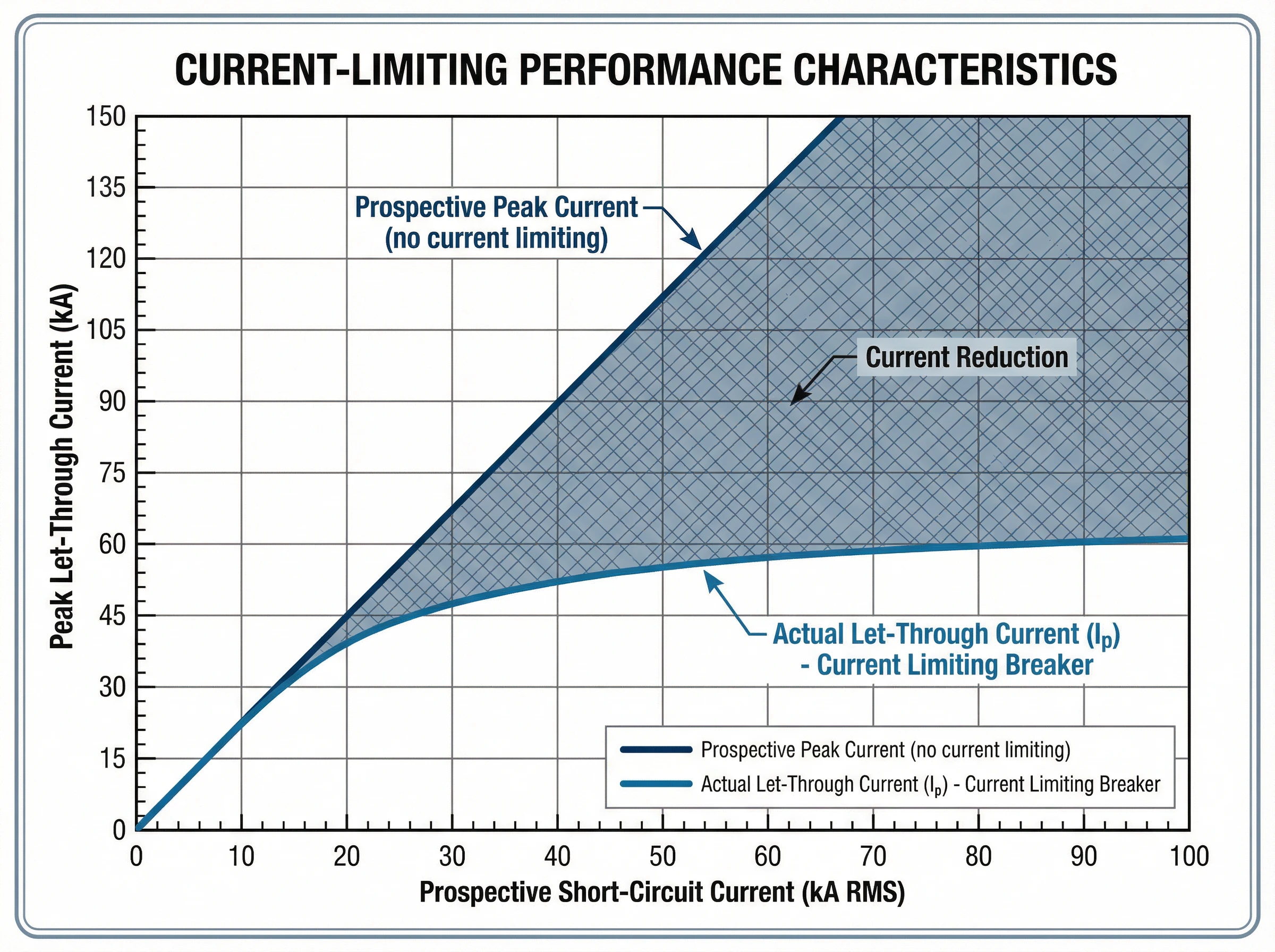
Manufacturers provide let-through current data in the form of characteristic curves. These graphs plot the peak let-through current (Ip) on the vertical axis against the prospective short-circuit current (RMS symmetrical amperes) on the horizontal axis. For any given prospective fault level at the installation point, the curve shows the maximum peak current that will actually flow.
For example, if the available fault current at a panelboard is 42,000 amperes RMS symmetrical, a current-limiting breaker might limit the actual peak current to just 18,000 amperes. This reduction from prospective to actual peak current protects busbars from bending, prevents conductor overheating, and reduces mechanical stress on all downstream components.
Thermal Stress (I²t)
នេះ។ I²t value (pronounced “I-squared-t”), measured in ampere-squared seconds (A²s), quantifies the thermal energy let through by the breaker during fault clearing. It represents the integral of the current squared over the total clearing time.
This specification is critical for protecting cables and sensitive electronic equipment. The insulation of cables has a specific thermal withstand rating expressed as I²t. If the protective device lets through more thermal energy than the cable can withstand, the insulation will be damaged even if the cable doesn’t physically melt.
Current-limiting breakers dramatically reduce I²t compared to standard breakers. For the same prospective fault current, a current-limiting device might have an I²t value 50-80% lower than a conventional breaker. This reduced thermal stress prevents conductor damage, protects cable insulation, and extends equipment life.
Manufacturers provide I²t curves similar to let-through current curves, showing the maximum thermal energy as a function of prospective fault current. Some standards define energy-limiting classes for circuit breakers based on their I²t performance.
Breaking Capacity (Icu and Ics)
នេះ។ សមត្ថភាពបំបែក defines the maximum fault current the breaker can safely interrupt. Two ratings are relevant under IEC 60947-2 (the international standard for low-voltage circuit breakers):
- សមត្ថភាពបំបែកចុងក្រោយ (Icu): The maximum fault current the breaker can interrupt without being destroyed. After interrupting a fault at Icu level, the breaker may not be suitable for continued service and might require replacement. This represents the breaker’s absolute upper limit.
- សមត្ថភាពបំបែកសេវាកម្ម (Ics): The maximum fault current the breaker can interrupt multiple times while remaining fully functional and reliable for continued service. Ics is expressed as a percentage of Icu (typically 50%, 75%, or 100%). For critical applications requiring high reliability, breakers with Ics = 100% Icu are preferred.
The fundamental selection rule is straightforward: the breaker’s Icu must be equal to or greater than the prospective short-circuit current at the point of installation. Current-limiting breakers can achieve high breaking capacities (50kA, 85kA, or higher) in compact form factors because the current-limiting action itself reduces the energy the breaker must handle.
The Interrelationship of Specifications
These specifications work together to define protection performance. When a fault occurs up to the breaker’s Icu rating, the current-limiting action reduces both the peak current (Ip) and the total thermal energy (I²t) to values far below what the prospective fault would produce. This coordinated reduction in peak mechanical stress and thermal damage is what makes current-limiting breakers essential for protecting modern electrical systems with high available fault currents.
Standards and Compliance
Current-limiting circuit breakers are governed by rigorous international and regional standards that define performance requirements, testing procedures, and safety criteria.
IEC 60947-2: International Standard
IEC 60947-2 is the international standard for low-voltage circuit breakers used in industrial and commercial applications. This comprehensive standard establishes:
- Performance categories: The standard distinguishes between Category A breakers (no intentional short-circuit time delay) and Category B breakers (with short-time withstand capability). Most modern current-limiting MCCBs are Category A devices.
- Breaking capacity verification: IEC 60947-2 specifies rigorous test sequences to verify both ultimate breaking capacity (Icu) and service breaking capacity (Ics). These tests involve multiple making and breaking operations under specified fault conditions.
- Current-limiting performance: While the standard doesn’t mandate current limitation, it provides test procedures to verify and document let-through current and I²t performance for breakers claiming current-limiting capability.
- Coordination and selectivity: The standard establishes requirements for back-up protection (cascading), where a current-limiting breaker upstream protects a downstream breaker with lower breaking capacity than the prospective fault current at its location.
UL 489: North American Standard
UL 489 is the Underwriters Laboratories standard for molded case circuit breakers in North America. Key provisions include:
- Current-limiting definition: UL 489 specifies that a circuit breaker qualifies as “current limiting” if it clears a fault in less than half a cycle (typically under 10 milliseconds for 60 Hz systems).
- Let-through testing: The standard requires extensive testing to generate let-through current curves that show the actual peak current as a function of prospective fault current.
- Short-circuit ratings: UL 489 defines interrupting ratings (IR) and establishes test procedures to verify breaker performance at rated voltage and current levels.
ការអនុលោមភាព និងការបញ្ជាក់
For electrical system designers and specifiers, standards compliance ensures:
- Verified performance: Certified breakers have undergone rigorous third-party testing to confirm their current-limiting capability and breaking capacity.
- Design confidence: Engineers can rely on published let-through curves and I²t data for equipment protection analysis and arc flash calculations.
- Regulatory acceptance: Standards-compliant breakers meet electrical code requirements in their respective markets (IEC zones or North American installations).
VIOX current-limiting circuit breakers are designed and tested to meet both IEC 60947-2 and UL 489 requirements, ensuring global applicability and verified protection performance.
កម្មវិធី និងករណីប្រើប្រាស់
Current-limiting circuit breakers deliver critical benefits in electrical systems where high available fault currents threaten equipment integrity and personnel safety.
Data Centers and Critical IT Infrastructure
Modern data centers face extraordinary fault current challenges. High-density server racks, powerful UPS systems, and multiple utility feeds create available fault currents that can exceed 65kA or more. Current-limiting breakers are essential in these environments:
- IT equipment protection: Servers, storage arrays, and networking gear contain sensitive electronics vulnerable to even brief overcurrent events. Current-limiting breakers reduce the fault energy to levels that prevent component damage.
- ការសម្របសម្រួលជ្រើសរើស: Data center reliability depends on isolating faults without cascading outages. Current-limiting breakers facilitate coordination between upstream and downstream protection, ensuring only the affected circuit trips.
- Arc flash mitigation: Maintenance personnel work on energized equipment regularly. By reducing peak fault current and clearing time, current-limiting breakers dramatically lower arc flash incident energy, improving worker safety and potentially reducing PPE requirements.
- Compact installations: Current-limiting technology enables high breaking capacity (50kA-100kA) in compact MCCBs, supporting dense power distribution without requiring oversized switchgear.
Industrial Manufacturing Facilities
Industrial plants with large motors, transformers, and extensive distribution networks face fault currents that can damage production equipment:
- មជ្ឈមណ្ឌលគ្រប់គ្រងម៉ូទ័រ: Protecting motor starters, variable frequency drives, and control electronics from fault current stress. Current-limiting breakers prevent damage to expensive drive electronics and ensure production continuity.
- High-capacity feeders: Where multiple power sources or large transformers create fault currents exceeding 50kA, current-limiting breakers provide protection without requiring expensive high-interrupting-capacity switchgear throughout the system.
- ការការពារឧបករណ៍: Busbars, cable trays, and panel components have mechanical strength limits. Current-limiting breakers reduce the magnetic forces during faults, preventing physical damage to distribution infrastructure.
Commercial Buildings with High Power Density
Office towers, hospitals, and retail centers increasingly deploy high-power systems:
- Main and sub-main distribution: Current-limiting breakers on main service entrances and distribution boards protect against utility-supplied fault currents while enabling effective downstream coordination.
- Emergency power systems: Generator and transfer switch protection where multiple sources increase available fault current.
- ការកែលម្អនិងការពង្រីកការបន្ថែមសមត្ថភាពទៅអគារដែលមានស្រាប់ជាញឹកញាប់បង្កើនកម្រិតចរន្តកំហុស។ ឧបករណ៍បំលែងសៀគ្វីកំណត់ចរន្ត ជួនកាលអាចលុបបំបាត់តម្រូវការសម្រាប់ការធ្វើឱ្យប្រសើរឡើងប្រព័ន្ធពេញលេញដោយផ្តល់នូវការការពារគ្រប់គ្រាន់នៅក្នុងការវាយតម្លៃហេដ្ឋារចនាសម្ព័ន្ធដែលមានស្រាប់។.
ការការពារជាដំណាក់កាល (ការការពារបម្រុងទុក)
កម្មវិធីមួយដែលមានតម្លៃបំផុតគឺការបើកដំណើរការការវាយតម្លៃជាដំណាក់កាល ឬស៊េរី។ ឧបករណ៍បំលែងសៀគ្វីកំណត់ចរន្តដែលបានដំឡើងនៅផ្នែកខាងលើអាចការពារឧបករណ៍បំលែងសៀគ្វីផ្នែកខាងក្រោមជាមួយនឹងសមត្ថភាពបំបែកទាបជាងចរន្តកំហុសដែលមានសក្តានុពលនៅទីតាំងរបស់វា។ នេះអនុញ្ញាតឱ្យ៖
- ការបង្កើនប្រសិទ្ធភាពចំណាយការប្រើប្រាស់ឧបករណ៍បំលែងសៀគ្វីដែលមានតម្លៃថោកជាង ដែលមានអត្រាទាបជាងនៅផ្នែកខាងក្រោម ខណៈពេលដែលរក្សាបាននូវការការពារពេញលេញ។.
- លក្ខណៈបច្ចេកទេសសាមញ្ញការធ្វើស្តង់ដារលើប្រភេទឧបករណ៍បំលែងសៀគ្វីទូទៅនៅទូទាំងកន្លែង ខណៈពេលដែលឧបករណ៍បំលែងសៀគ្វីមេកំណត់ចរន្តផ្តល់នូវការការពារទូទាំងប្រព័ន្ធ។.
- ភាពបត់បែននៃប្រព័ន្ធការបន្ថែមសៀគ្វី ឬបន្ទុកដោយមិនចាំបាច់ធ្វើឱ្យប្រសើរឡើងនូវឧបករណ៍ការពារផ្នែកខាងក្រោមទាំងអស់។.
ការកំណត់ចរន្តធៀបនឹងឧបករណ៍បំលែងសៀគ្វីស្តង់ដារ
ការយល់ដឹងអំពីភាពខុសគ្នារវាងការកំណត់ចរន្ត និងឧបករណ៍បំលែងសៀគ្វីស្តង់ដារ បញ្ជាក់នៅពេលដែលបច្ចេកវិទ្យានីមួយៗគឺសមរម្យ។.
វិធីសាស្ត្ររំខាន
ឧបករណ៍បំលែងស្តង់ដារឧបករណ៍បំលែងសៀគ្វីធម្មតារកឃើញកំហុស និងចាប់ផ្តើមយន្តការធ្វើដំណើរ ប៉ុន្តែអនុញ្ញាតឱ្យចរន្តកំហុសកើនឡើងដល់តម្លៃកំពូលដែលមានសក្តានុពលរបស់វា។ ការរំខានកើតឡើងនៅ ឬជិតសូន្យឆ្លងកាត់ចរន្តធម្មជាតិ ជាធម្មតាបន្ទាប់ពី 0.5 ទៅ 1.5 វដ្ត (8-25 មិល្លីវិនាទីនៅ 60 Hz)។ ក្នុងអំឡុងពេលនេះ ចរន្តកំហុសពេញលេញសង្កត់ធ្ងន់លើប្រព័ន្ធ។.
ឧបករណ៍បំលែងសៀគ្វីកំណត់ចរន្តឧបករណ៍ទាំងនេះធ្វើសកម្មភាពក្នុងរយៈពេលប៉ុន្មានមីលីវិនាទីដើម្បីរំខានចរន្តដោយបង្ខំ មុនពេលវាឈានដល់កម្រិតកំពូលដែលមានសក្តានុពលរបស់វា។ តាមរយៈការបំបែកទំនាក់ទំនងអេឡិចត្រូឌីណាមិក និងការបង្កើតវ៉ុលធ្នូ ពួកគេជម្រះកំហុសក្នុងរយៈពេលតិចជាងពាក់កណ្តាលវដ្ត (ក្រោម 10 មិល្លីវិនាទី) ដែលកាត់បន្ថយយ៉ាងខ្លាំងទាំងចរន្តកំពូល និងថាមពលកំហុសសរុប។.
ចរន្តកំពូល និងភាពតានតឹងមេកានិច
ឧបករណ៍បំលែងស្តង់ដារចរន្តកំហុសដែលមានសក្តានុពលពេញលេញហូរ បង្កើតកម្លាំងម៉ាញ៉េទិចអតិបរមា។ សម្រាប់កំហុសដែលមានសក្តានុពល 50kA ពេញ 50kA (កំពូល asymmetrical 70kA) បង្កើតភាពតានតឹងមេកានិចយ៉ាងខ្លាំងនៅលើ busbars, terminals និងការតភ្ជាប់។.
ឧបករណ៍បំលែងសៀគ្វីកំណត់ចរន្តចរន្តអនុញ្ញាតត្រូវបានកាត់បន្ថយយ៉ាងខ្លាំង។ សម្រាប់កំហុសដែលមានសក្តានុពល 50kA ដូចគ្នា ឧបករណ៍បំលែងសៀគ្វីកំណត់ចរន្តអាចកំណត់កម្រិតកំពូលពិតប្រាកដត្រឹម 15-20kA ដែលកាត់បន្ថយកម្លាំងម៉ាញ៉េទិចដោយ 60-70% ។.
ថាមពលកម្ដៅ (I²t)
ឧបករណ៍បំលែងស្តង់ដារពេលវេលាជម្រះយូរ និងចរន្តកំពូលខ្ពស់បណ្តាលឱ្យមានការបញ្ចេញថាមពលកម្ដៅយ៉ាងច្រើន។ ខ្សែ, busbars និងការតភ្ជាប់ស្រូបយកកំដៅយ៉ាងសំខាន់ដែលអាចបំផ្លាញអ៊ីសូឡង់។.
ឧបករណ៍បំលែងសៀគ្វីកំណត់ចរន្តចរន្តកំពូលដែលបានកាត់បន្ថយ និងការសម្អាតលឿនបំផុតកាត់បន្ថយតម្លៃ I²t យ៉ាងខ្លាំង ជាញឹកញាប់ដោយ 50-80% ។ នេះការពារអ៊ីសូឡង់ខ្សែ ការពារការដុតនំចំហាយ និងការពារគ្រឿងអេឡិចត្រូនិចដែលងាយរងគ្រោះពីភាពតានតឹងកម្ដៅ។.
ថាមពលឧប្បត្តិហេតុ Arc Flash
ឧបករណ៍បំលែងស្តង់ដារចរន្តកំហុសខ្ពស់ និងពេលវេលាជម្រះយូរបង្កើនថាមពលឧប្បត្តិហេតុពន្លឺធ្នូ ដែលតម្រូវឱ្យមាន PPE កម្រិតខ្ពស់ និងបង្កើតគ្រោះថ្នាក់សុវត្ថិភាពកាន់តែច្រើនសម្រាប់បុគ្គលិកថែទាំ។.
ឧបករណ៍បំលែងសៀគ្វីកំណត់ចរន្តទំហំ និងរយៈពេលនៃចរន្តកំហុសដែលបានកាត់បន្ថយបន្ថយថាមពលពន្លឺធ្នូយ៉ាងខ្លាំង។ នេះអាចបន្ថយព្រំដែនពន្លឺធ្នូ កាត់បន្ថយតម្រូវការ PPE និងធ្វើអោយប្រសើរឡើងនូវសុវត្ថិភាពអគ្គិសនីទាំងមូល។.
ការចំណាយ និងការសម្របសម្រួលភាពស្មុគស្មាញ
ឧបករណ៍បំលែងស្តង់ដារជាទូទៅមានតម្លៃថោកជាងក្នុងមួយឯកតា។ ស័ក្តិសមសម្រាប់កម្មវិធីដែលចរន្តកំហុសមានកម្រិតមធ្យម ហើយការវាយតម្លៃឧបករណ៍លើសពីកម្រិតកំហុសដែលមាន។.
ឧបករណ៍បំលែងសៀគ្វីកំណត់ចរន្តការចំណាយដំបូងខ្ពស់ជាង ប៉ុន្តែអាចកាត់បន្ថយការចំណាយប្រព័ន្ធសរុបដោយ៖
- អនុញ្ញាតឱ្យសមាសធាតុផ្នែកខាងក្រោមស្រាលជាងមុន
- ការបើកដំណើរការការការពារជាដំណាក់កាលជាមួយនឹងឧបករណ៍បំលែងសៀគ្វីដែលមានអត្រាទាបជាង
- កាត់បន្ថយតម្រូវការការពង្រឹងបន្ទះ
- ការពារឧបករណ៍ដែលមានតម្លៃថ្លៃពីការខូចខាត
- កាត់បន្ថយការចំណាយលើការកាត់បន្ថយពន្លឺធ្នូ
ពេលណាត្រូវជ្រើសរើសប្រភេទនីមួយៗ
ជ្រើសរើសឧបករណ៍បំលែងស្តង់ដារនៅពេល:
- ចរន្តកំហុសដែលមានគឺទាបជាងការវាយតម្លៃសៀគ្វីខ្លីរបស់ប្រព័ន្ធ
- ការរឹតបន្តឹងថវិកាមានសារៈសំខាន់ ហើយកម្រិតកំហុសមិនសមហេតុផលចំពោះការការពារការកំណត់ចរន្ត
- ការសម្របសម្រួលអាចត្រូវបានសម្រេចដោយគ្មានការកំណត់ចរន្ត
ជ្រើសរើសឧបករណ៍បំលែងសៀគ្វីកំណត់ចរន្តនៅពេល:
- ចរន្តកំហុសដែលមានលើសពី 20-25kA
- ការការពារឧបករណ៍អេឡិចត្រូនិកដែលងាយរងគ្រោះ (មជ្ឈមណ្ឌលទិន្នន័យ ប្រព័ន្ធគ្រប់គ្រង)
- ស្វែងរកការកាត់បន្ថយគ្រោះថ្នាក់ពន្លឺធ្នូ
- ការបើកដំណើរការការការពារជាដំណាក់កាលដើម្បីកាត់បន្ថយការចំណាយ
- ការពង្រីកកន្លែងបានបង្កើនកម្រិតកំហុសលើសពីការវាយតម្លៃឧបករណ៍ដើម
លក្ខណៈវិនិច្ឆ័យជ្រើសរើស
ការជ្រើសរើសឧបករណ៍បំលែងសៀគ្វីកំណត់ចរន្តត្រឹមត្រូវតម្រូវឱ្យមានការវាយតម្លៃកត្តាបច្ចេកទេស និងកម្មវិធីជាច្រើន។.
គណនាចរន្តកំហុសដែលមាន
ជំហានដំបូងគឺការកំណត់ចរន្តសៀគ្វីខ្លីដែលមានសក្តានុពលនៅចំណុចដំឡើង។ នេះទាមទារ:
- សមត្ថភាព និង impedance របស់ឧបករណ៍បំលែងឧបករណ៍ប្រើប្រាស់
- ប្រវែង និងទំហំនៃចំហាយ
- ភាពធន់នៃសមាសធាតុចែកចាយ
- ការរួមចំណែកពីម៉ូទ័រនិងម៉ាស៊ីនភ្លើង
ឧបករណ៍ប្រើប្រាស់ជាច្រើនផ្តល់ទិន្នន័យចរន្តកំហុស ឬវិស្វករអគ្គិសនីដែលមានលក្ខណៈសម្បត្តិគ្រប់គ្រាន់អាចអនុវត្តការគណនាសៀគ្វីខ្លីដោយប្រើវិធីសាស្ត្រស្តង់ដារឧស្សាហកម្ម (IEC 60909 ឬស្តង់ដារ IEEE)។ សមត្ថភាពបំបែកចុងក្រោយរបស់ឧបករណ៍បំបែក (Icu) ត្រូវតែបំពេញ ឬលើសពីចរន្តកំហុសដែលបានគណនានេះ។.
វាយតម្លៃតម្រូវការការពារឧបករណ៍
ពិចារណាអ្វីដែលត្រូវការការការពារ៖
- គ្រឿងអេឡិចត្រូនិចរសើប: មជ្ឈមណ្ឌលទិន្នន័យ ប្រព័ន្ធគ្រប់គ្រង និងឧបករណ៍ទូរគមនាគមន៍ទទួលបានអត្ថប្រយោជន៍យ៉ាងសំខាន់ពីការកាត់បន្ថយចរន្តអនុញ្ញាត និង I²t ។.
- ការវាយតម្លៃ Busbar និង conductor: ប្រសិនបើចរន្តកំហុសខិតជិត ឬលើសពីការវាយតម្លៃធន់នឹងសៀគ្វីខ្លីនៃ busbars ខ្សែ ឬសមាសធាតុបន្ទះ ការកំណត់បច្ចុប្បន្នមានសារៈសំខាន់។.
- ឧបករណ៍ដែលមានស្រាប់: នៅពេលពង្រីកគ្រឿងបរិក្ខារ ឧបករណ៍បំបែកដែនកំណត់បច្ចុប្បន្ន ជួនកាលអាចការពារហេដ្ឋារចនាសម្ព័ន្ធដែលមានស្រាប់ដោយមិនចាំបាច់ជំនួសទាំងស្រុង។.
វាយតម្លៃតម្រូវការកាត់បន្ថយគ្រោះថ្នាក់ Arc Flash
ប្រសិនបើការសិក្សាអំពី arc flash បង្ហាញពីកម្រិតថាមពលឧប្បត្តិហេតុខ្ពស់ដែលតម្រូវឱ្យមាន PPE យ៉ាងទូលំទូលាយ ឬបង្កើតគ្រោះថ្នាក់ដល់កម្មករដែលមិនអាចទទួលយកបាន ឧបករណ៍បំបែកដែនកំណត់បច្ចុប្បន្នអាចកាត់បន្ថយថាមពល arc flash យ៉ាងខ្លាំង។ ពិនិត្យមើលការគណនា arc flash ដើម្បីកំណត់ថាតើដែនកំណត់បច្ចុប្បន្ននឹងបន្ថយកម្រិតគ្រោះថ្នាក់ និងធ្វើអោយប្រសើរឡើងនូវសុវត្ថិភាពដែរឬទេ។.
ពិចារណាតម្រូវការសម្របសម្រួល
ការសម្របសម្រួលជ្រើសរើស—ធានាថាតែឧបករណ៍បំបែកដែលនៅជិតបំផុតនឹងការធ្វើដំណើរខុស—គឺមានសារៈសំខាន់នៅក្នុងកម្មវិធីជាច្រើន៖
- ការការពារ Cascading: ប្រសិនបើឧបករណ៍បំបែកផ្នែកខាងក្រោមមានសមត្ថភាពបំបែកទាបជាងចរន្តកំហុសដែលមាន ឧបករណ៍បំបែកដែនកំណត់បច្ចុប្បន្ននៅផ្នែកខាងលើអាចផ្តល់ការការពារបម្រុងទុក។.
- ការផ្ទុកសំខាន់: មជ្ឈមណ្ឌលទិន្នន័យ មន្ទីរពេទ្យ និងដំណើរការឧស្សាហកម្មទាមទារឱ្យមានការដាច់ចរន្តដោយមិនមានការដាច់ចរន្តដែលមិនចាំបាច់។ ឧបករណ៍បំបែកដែនកំណត់បច្ចុប្បន្នជួយសម្រួលដល់ការសម្របសម្រួលដោយកាត់បន្ថយថាមពលអនុញ្ញាត។.
ពិនិត្យមើលខ្សែកោងបច្ចុប្បន្ន
ក្រុមហ៊ុនផលិតផ្តល់ចរន្តអនុញ្ញាត (Ip) និងខ្សែកោង I²t សម្រាប់ឧបករណ៍បំបែកដែនកំណត់បច្ចុប្បន្នរបស់ពួកគេ។ ប្រៀបធៀបខ្សែកោងទាំងនេះទល់នឹង៖
- ការវាយតម្លៃធន់នឹងឧបករណ៍
- ដែនកំណត់ខ្សែ I²t
- គោលដៅកាត់បន្ថយថាមពល Arc flash
- តម្រូវការសម្របសម្រួលជាមួយឧបករណ៍ផ្នែកខាងក្រោម
ផ្ទៀងផ្ទាត់ការអនុលោមតាមស្តង់ដារ
ធានាថាឧបករណ៍បំបែកបំពេញតាមស្តង់ដារដែលអាចអនុវត្តបាន៖
- IEC 60947-2 សម្រាប់កម្មវិធីអន្តរជាតិ/ឧស្សាហកម្ម
- UL 489 សម្រាប់ការដំឡើងនៅអាមេរិកខាងជើង
- លេខកូដអគ្គិសនីក្នុងស្រុក និងតម្រូវការវិញ្ញាបនប័ត្រ
សេចក្តីសន្និ
ឧបករណ៍បំបែកសៀគ្វីកំណត់បច្ចុប្បន្នតំណាងឱ្យការរីកចម្រើនដ៏សំខាន់នៅក្នុងបច្ចេកវិទ្យាការពារអគ្គិសនី ដោយដោះស្រាយបញ្ហាជាមូលដ្ឋាននៃចរន្តកំហុសខ្ពស់នៅក្នុងប្រព័ន្ធថាមពលទំនើប។ ដោយការរំខានដល់កំហុសក្នុងរយៈពេលប៉ុន្មានមីលីវិនាទី និងកាត់បន្ថយយ៉ាងខ្លាំងនូវចរន្តអនុញ្ញាតកំពូល និងភាពតានតឹងកម្ដៅ ឧបករណ៍ទាំងនេះការពារឧបករណ៍ដែលមានតម្លៃថ្លៃ ធ្វើអោយប្រសើរឡើងនូវសុវត្ថិភាពបុគ្គលិក និងអនុញ្ញាតឱ្យមានការរចនាប្រព័ន្ធដែលអាចបត់បែនបានជាងមុន។.
សម្រាប់វិស្វករអគ្គិសនី និងអ្នកគ្រប់គ្រងគ្រឿងបរិក្ខារដែលធ្វើការជាមួយប្រព័ន្ធចែកចាយថាមពលខ្ពស់—ជាពិសេសមជ្ឈមណ្ឌលទិន្នន័យ គ្រឿងបរិក្ខារឧស្សាហកម្ម និងអគារពាណិជ្ជកម្មដែលមានចរន្តកំហុសលើសពី 25kA—បច្ចេកវិទ្យាកំណត់បច្ចុប្បន្នផ្តល់នូវអត្ថប្រយោជន៍ដែលអាចវាស់វែងបានក្នុងការការពារឧបករណ៍ ការកាត់បន្ថយ arc flash និងភាពបត់បែននៃការសម្របសម្រួល។ លក្ខណៈបច្ចេកទេសសំខាន់ៗ (ចរន្តអនុញ្ញាត Ip, ភាពតានតឹងកម្ដៅ I²t និងសមត្ថភាពបំបែក Icu) ផ្តល់ទិន្នន័យវិស្វកម្មដែលត្រូវការដើម្បីផ្ទៀងផ្ទាត់ដំណើរការការពារ និងធានាបាននូវប្រតិបត្តិការប្រកបដោយសុវត្ថិភាព និងអាចទុកចិត្តបាន។.
VIOX Electric ផលិតឧបករណ៍បំបែកសៀគ្វីកំណត់បច្ចុប្បន្នដែលត្រូវបានរចនាឡើងតាមស្តង់ដារ IEC 60947-2 និង UL 489 ដោយផ្តល់នូវសមត្ថភាពបំបែកពី 35kA ដល់ 100kA និងខ្សែកោងដំណើរការអនុញ្ញាតដ៏ទូលំទូលាយ។ សម្រាប់លក្ខណៈបច្ចេកទេស ការណែនាំអំពីកម្មវិធី ឬដើម្បីពិភាក្សាអំពីតម្រូវការការពារជាក់លាក់របស់អ្នក សូមទាក់ទងក្រុមវិស្វកម្មរបស់ VIOX ។.
ការពារហេដ្ឋារចនាសម្ព័ន្ធសំខាន់របស់អ្នកជាមួយនឹងបច្ចេកវិទ្យាកំណត់បច្ចុប្បន្នដែលបានបញ្ជាក់។. ទាក់ទង VIOX Electric ដើម្បីពិភាក្សាអំពីតម្រូវការការពារសៀគ្វីរបស់អ្នក។.
