

Di halaman ini
A cam switch switching program is the schedule of which contact pairs are open or closed at every handle position. The same position markings can operate different contact combinations. Read the position columns and terminal-pair rows, match them to the handle diagram, then compare the documented states with an isolated-switch continuity record.
This guide uses a real cam-switch target table from the Basic Controls material included in Massachusetts Maritime Academy’s electrical machines course manual. It works through the stop column, the direction columns and the shared contact row before explaining the multimeter method. The teaching example is not a VIOX model specification. Always obtain the drawing for the exact unit being tested.
Continuity testing is de-energized work only. Qualified personnel must isolate every relevant supply, secure against reconnection and verify absence of voltage before disconnecting or probing a switch. A multimeter’s continuity function is not an absence-of-voltage test.
What the Program Physically Is
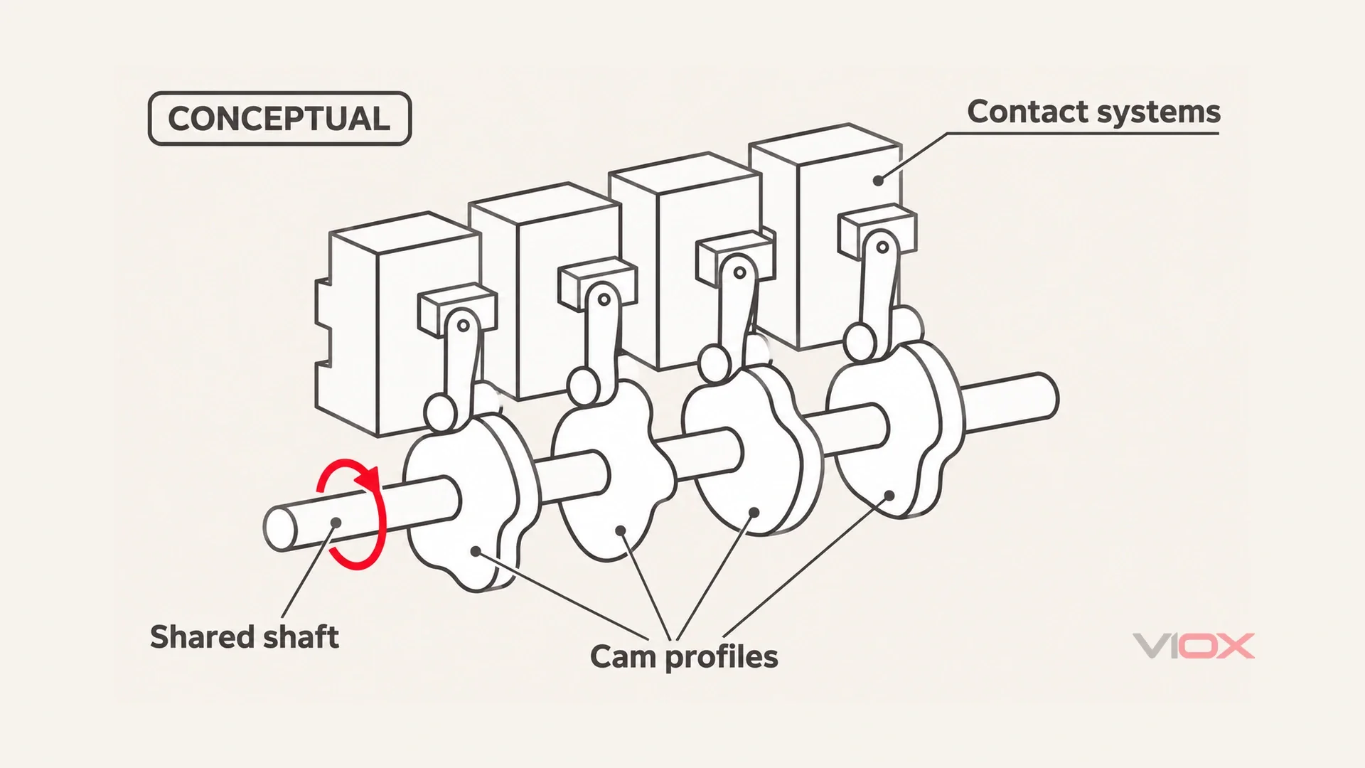
A cam switch coordinates contact sets through a common rotating shaft and shaped cam profiles. Turning the handle moves the profiles relative to their followers, changing the contact states. Contact systems are arranged in stacked sections or decks; their operating pattern is mechanical rather than software loaded into the device.
The important relationship is between shaft position and contact state. Contacts can close together, open together or operate in different combinations. A front plate tells the operator where to turn; it cannot reveal all the resulting electrical paths.
A section is a physical contact-system layer. It is not automatically a single row in a contact table, a single pole or a complete independent external circuit. Follow the manufacturer’s layer arrangement and terminal map. Counting visible decks and assigning an imagined contact pair to each is not a reliable way to reconstruct a missing program.
For operator terminology, the selector switch definition guide separates handle style, maintained or momentary action and contact logic. Electrical-duty decisions belong in the cam switch technical selection guide; a correctly read program does not itself establish a suitable load rating.
Anatomy of a Contact Table
Start with an actual published table, not an invented demonstration grid. The course material’s “Target table of the Cam Switch” places contact pairs down the left and the handle states F, O and R across the top. It is a forward/off/reverse teaching example; its contact numbers must not be transferred to another switch by appearance.
Table 1. Published cam-switch target table
| Contact pair | F | O | R |
|---|---|---|---|
| 1-2 | X | ||
| 3-4 | X | ||
| 5-6 | X | ||
| 7-8 | X | ||
| 9-10 | X | X |
Referensi: Basic Controls, Table 2-11, “Target table of the Cam Switch,” in the Massachusetts Maritime Academy EN 3111L course manual, printed page 2-21, PDF page 187. X means closed; blank means open. Terminal labels are normalized to plain hyphens without changing states.
Find the position column first
Choose the column corresponding to the handle’s actual marked position. In column F, read downward: 1-2 is closed, 3-4 is open, 5-6 is open, 7-8 is closed and 9-10 is closed. Column O contains no closure marks, so the listed pairs are open there.
This column-first method answers the operating question: “What is connected now?” Reading a single row across instead answers a different question: “At which positions does this particular pair close?” Both are useful, but mixing the two directions is a common source of incorrect records.
Treat each row as a named terminal pair
The row 1-2 means continuity between terminals marked 1 and 2 on the documented switch. It does not mean that terminal 1 connects to every other terminal in column F. Nor is a terminal number automatically a phase, supply or load designation.
Locate the actual molded or printed terminal markings on the isolated device. Do not assume the first visible screw is terminal 1, or that the rear view has the same left-to-right orientation as a front-view drawing. Record the viewing direction and any manufacturer’s section layout.
Read the legend, not just the symbol
This teaching table uses X for a closed pair. Another drawing may use a dot, bar or differently oriented matrix. Confirm its legend before translating anything into a truth table. Keep the source’s position labels and pair identities even when changing the page layout for readability.
A contact-state grid also has a boundary: it lists states at the specified positions. Without additional documentation, it does not establish the contact overlap, opening sequence or behavior between those positions.
The Handle Diagram: Match Position, Angle and Return Action
The handle diagram is the map between the front plate and the table columns. Read it beside the contact schedule. A position called 1 in a diagram must be matched to that same marked position on the supplied assembly, not merely to the first detent reached clockwise.
LW26 documentation includes 30°, 45°, 60° and 90° switching arrangements. These are available arrangements, not angles to apply indiscriminately to every program. Determine the angle and reference orientation from the exact drawing. Similar-looking handles can have different stops, travel and position spacing.
Maintained positions remain selected after release. A spring-return position is a defined electrical position that the operator reaches against a restoring action. It still needs a column in the contact schedule; it does not disappear from the program because the handle will not remain there unattended.
The actual manufacturer’s operation diagram must identify the return behavior and reference position. A rotation arrow, return arrow and mechanical-stop indication serve different purposes; interpret them under that drawing’s legend. Do not decide that a position is maintained or momentary simply from the shape of the front handle.
The centre label O in Table 1 denotes the off state in this source. Other switches may use 0, OFF or another label. Preserve the actual label in the record. An off marking is not, by itself, evidence that every conductor in the equipment is isolated.
Record the complete product and program reference, whose format is manufacturer-specific, when requesting the exact diagram through the VIOX LW26 product page.
Worked Reading 1: Establish the Off State
The following worked readings all use Table 1. They are different ways to interrogate one documented program, not different factory programs or measured results.
Start with column O. Every listed row is blank: 1-2, 3-4, 5-6, 7-8 and 9-10 are open. That is a complete statement about these documented pairs in this position. It does not say anything about unlisted conductors, other switching devices or the isolation status of the machine.
This distinction prevents a common bench-record error. If a technician writes “OFF = no continuity” without identifying which pairs were checked, the record cannot be compared reliably with the source. Record each pair’s state even when an entire column appears simple.
Next read a row back across the table as a cross-check. Pair 1-2 is closed at F, open at O and open at R. That agrees with the column reading. If a handwritten record says otherwise, investigate the position label, row alignment and actual observation before blaming the switch.
An all-open stop column is valuable information, but it is not a universal feature of every control program. Some applications intentionally retain a signaling path in a neutral operator position. The actual drawing, not the word printed on the front, determines the expected state.
Worked Reading 2: Compare the Direction Columns
Read column F from top to bottom. The closed pairs are 1-2, 7-8 and 9-10. Pairs 3-4 and 5-6 are open. Read R independently: 3-4, 5-6 and 9-10 are closed, while 1-2 and 7-8 are open.
Now separate the alternating paths from the shared path. The first and fourth rows operate in F; the second and third operate in R. The final row participates in both active states. This is information obtained from the table, not inferred from the word “reverse”.
The associated source drawing shows the surrounding relationships used by its training circuit. Those relationships are not reproduced here as a motor-wiring procedure. A contact table by itself does not identify every field connection or authorize a particular reversal arrangement on another machine.
Where external conductors go is a separate task. The cam switch wiring diagram guide introduces that task; actual connections and terminal requirements must follow the exact switch and machine documentation. Do not turn a contact-pair list into an improvised installation diagram.
The reading also has a transition limit. Matching F, O and R states does not establish how the contacts behave while the handle travels between them. Where contact overlap or break-before-make operation matters, obtain that information from the exact device documentation. A position table is not a timing certificate.
Worked Reading 3: Follow the Shared Row Across Positions
Read pair 9-10 horizontally: closed at F, open at O and closed at R. Calling it “the common row” is convenient only if the statement remains precise. It is shared by the active positions in this particular program; it is not closed at every position.
Nor does “common row” mean that terminal 9 is a universal supply common, or that it connects internally to all the other contact pairs. A matrix describes a pair’s state. Any permanent bridge or external commoning arrangement must be established separately from the actual circuit drawing.
This is a useful final check on a contact schedule: identify any row that remains closed across multiple operating positions, then check the exceptions. Do not fill a blank cell merely because the neighboring cells contain X marks. An unexpected open state may be an intended part of the program.
The same discipline applies when comparing a replacement. A candidate could match the alternating rows but differ on a shared path. Front labels and partial continuity checks would miss that difference. Every relevant row and position must agree with the required program before the separate questions of ratings, mounting and transition behavior are considered.
For a program without a shared active-position row, the correct conclusion would be that no such row exists. The table-reading method requires observing that result, not forcing every application into the pattern of this teaching example.
Verify It Yourself: The Multimeter Truth Table
The manufacturer’s contact table is the expected schedule. Your continuity record is the observed schedule. Keep them separate until the observations are complete, so that an expected X is not copied into the results without a measurement.
Establish a safe, identifiable test object
Have qualified personnel isolate the equipment, prevent reconnection and verify dead by the applicable procedure. Identify backfeeds and stored-energy sources as relevant. Do not select continuity mode or attach probes until the switch and connected circuit are confirmed de-energized.
Record the switch identity, full markings, front-plate legend and drawing reference. Photograph terminal markings and existing connections before any necessary disconnection. A useful continuity record must remain traceable to the unit and the view being described.
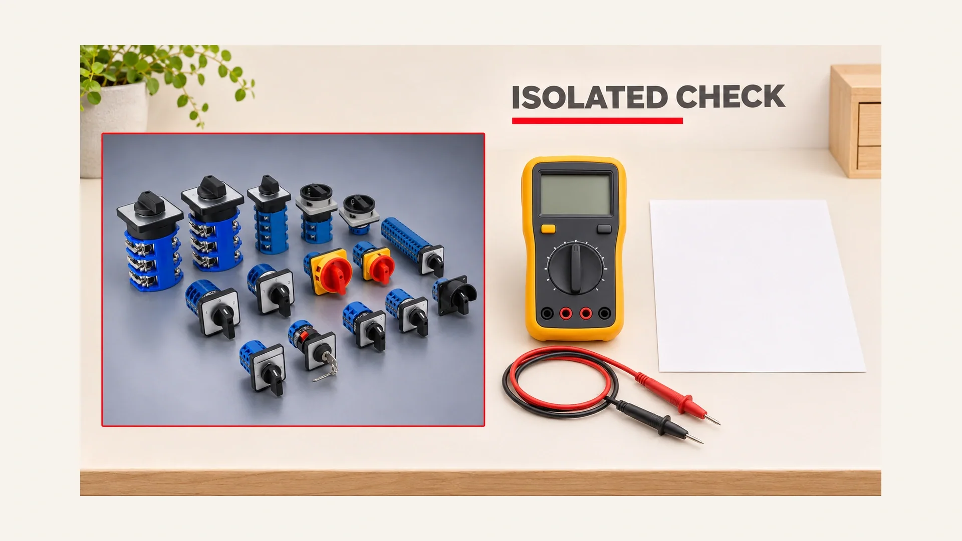
External conductors and links can create parallel paths that make an open contact appear closed. Establish the test boundary before interpreting the meter. Identify documented factory connections separately from installation wiring, and do not remove internal parts or dismantle the cam stack to obtain a convenient result.
If the switch cannot be safely isolated from misleading paths, stop and resolve that boundary. A continuity map of the surrounding circuit is not automatically a map of the switch’s own contacts.
Record each position and pair consistently
Prepare a record with the manufacturer’s position labels across the top and its listed contact pairs down the side. Include the legend defining the recorded open and closed states. This is the same information structure as the published example, not a new, guessed program.
Check that the meter and leads function correctly by the instrument’s instructions. Identify the actual terminal pair from its markings, select the documented handle position, and record the observed continuity state. Continue until every listed pair has a result at every listed position.
Keep position labels, viewing direction and pair identities consistent throughout. For a spring-return position, use only a safe method appropriate to the isolated device to maintain that position during observation. Do not wedge or modify the mechanism, and do not omit the position because it returns when released.
An unclear or intermittent indication is a result to investigate, not a reason to fill the cell with the expected state. Recheck identification, probe contact and the test boundary before interpreting it as a failed contact. Do not invent a universal resistance threshold: use the manufacturer’s requirements and the instrument’s capabilities.
Compare the completed record cell by cell
Start with the position labels and pair list, then compare every observed state against the exact source diagram. A mismatch can mean several different things:
- Different supplied program: a repeatable, different pattern may indicate the wrong drawing or configuration. Confirm the complete reference before calling it a manufacturing defect.
- A pair fails to close as documented: after excluding identification and test-path errors, contact damage, wear or a mechanical problem becomes a reason for further assessment.
- Unexpected pattern after dismantling: a previously disassembled unit may have an incorrect section order or cam arrangement. Stop use pending an appropriate manufacturer assessment; this guide does not authorize rebuilding it by trial and error.
Keep these as interpretations to confirm. No pattern in this article is a fabricated measurement of a particular supplied switch.
Keep the conclusion within the test’s limits
A matching continuity record establishes agreement at the tested positions under those conditions. It does not certify load-breaking duty, insulation performance, contact pressure under service conditions or the opening sequence between detents.
When an old switch has no recoverable drawing, preserve the measured record as an input to a replacement enquiry, together with its condition and uncertainty. A worn device can fail to reveal its original intended state. Therefore, the observed pattern is evidence to review against the machine’s requirements, not an instruction to reproduce every old result in a new product.
PERTANYAAN YANG SERING DIAJUKAN
What is the difference between a switching program and a wiring diagram?
A program lists contact states at handle positions. A wiring diagram shows conductor connections and the surrounding circuit. They complement each other. A correct contact schedule alone does not establish where field conductors should be connected or whether the application is suitable.
Can two cam switches with the same positions have different programs?
Yes. Handle labels and detents describe the operator interface; cam profiles determine the contact combinations. Matching the front plate does not establish matching logic. Compare the exact diagrams and, where appropriate, isolated continuity records.
Where do I find the program of a switch I already have?
Record its full nameplate, reference and handle markings, then obtain the manufacturer’s corresponding diagram. If the reference is missing or unreadable, a qualified person’s isolated continuity map can document observed states. It cannot recover missing ratings or guarantee the original intent of damaged contacts.
What does the number of sections mean in a contact table?
Sections are physical contact-system layers, not automatically the number of matrix rows. Rows identify the contact pairs specified by that drawing. Use the manufacturer’s section arrangement to relate the table to the assembly; do not equate deck count, row count and external circuit count.
A position on my switch springs back — is it in the table too?
Yes. A momentary position still has defined contact states while reached. Identify it from the operation-and-position diagram and include its column in the isolated record. The return action describes what happens when the operator releases the handle; it does not replace the contact schedule.
Sumber
- Massachusetts Maritime Academy, EN 3111L Electrical Machines Lab course manual: its Basic Controls teaching material contains Table 2-11, “Target table of the Cam Switch,” printed page 2-21/PDF page 187. This is the source for the contact states, not a VIOX model declaration.
- OSHA 1910.333, Selection and use of work practices: U.S. workplace guidance on de-energization, control of energy and verification before work. Local requirements and equipment instructions remain applicable.
- VIOX LW26 rotary cam switch product information: product exterior, modular contact sections, maintained/spring-return mechanisms and available switching-angle options. The teaching table is not a VIOX program-availability list.