
Selecting the appropriate busbar for your Miniature Circuit Breaker (MCB) system is a critical decision that directly impacts the safety, reliability, and performance of your electrical installation. With various materials, configurations, and specifications available in the market, making an informed choice can be challenging. This comprehensive guide will walk you through the essential factors to consider when selecting busbars for MCBs, helping you make decisions based on technical requirements, safety standards, and budget considerations.
What Is a Busbar and Why Is It Important?

A busbar is a metallic conductor that serves as a common connection point for multiple electrical circuits in a power distribution system. In MCB applications, busbars collect electricity from incoming feeders and distribute it to outgoing circuits, simplifying wiring and ensuring efficient power distribution.
These conductive bars function as central distribution hubs within electrical panels, switchboards, and substations, providing a common, low-impedance pathway to efficiently distribute electrical power from one or more incoming sources to multiple outgoing circuits. In the context of MCB installations, busbars significantly simplify the process of connecting and supplying power to numerous breakers, replacing complex wiring harnesses and reducing installation time and potential errors.
The quality and appropriateness of your busbar selection directly impact:
- System reliability and operational safety
- Power distribution efficiency
- Installation time and complexity
- Maintenance requirements and accessibility
- Overall electrical system performance
Understanding Miniature Circuit Breakers (MCBs)
Miniature Circuit Breakers are electromechanical devices fundamental to modern electrical safety. They are designed to automatically interrupt the flow of electrical current when it exceeds safe levels due to either overload conditions or short circuits, thereby protecting wiring, connected appliances, and personnel.
MCBs operate using two primary mechanisms:
- Thermal Operation (Overload Protection): Inside the MCB, a bimetallic strip is calibrated to heat up and bend when the current flowing through it exceeds the breaker’s rated current for a sustained period. This bending action eventually triggers a mechanical latch, causing the contacts to open and interrupt the circuit.
- Magnetic Operation (Short Circuit Protection): MCBs also contain an electromagnetic coil or solenoid. In the event of a short circuit, the current rises dramatically and very rapidly. This sudden surge creates a strong magnetic field in the coil, which instantly trips the mechanical latch, interrupting the circuit within a fraction of a second.
Types of Busbars for MCBs
Several busbar types are commonly used with MCBs, each designed for specific applications:
- Pin-type busbars: Feature pins that plug directly into compatible spring-loaded or screw-clamp terminals on the MCBs, providing secure connections with wider contact areas.
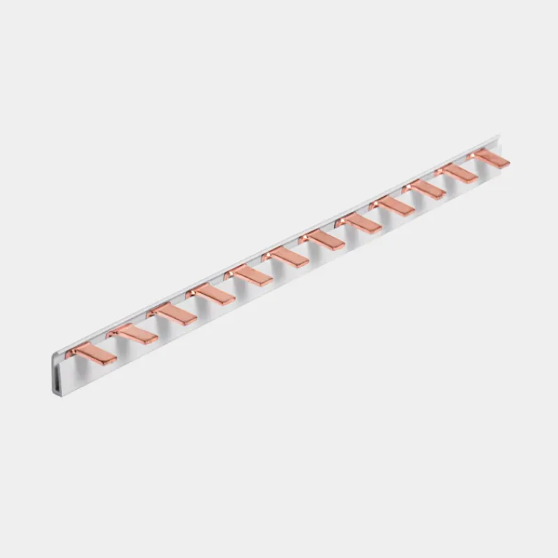
- Fork-type busbars: Utilize fork-shaped connectors that wrap around terminal screws for reliable connections.

- Comb-type busbars: Arranged in a comb pattern for easy connection of multiple MCBs, offering simplified installation.
- Enclosed busbar systems: Provide additional protection with a shared enclosure, enhancing safety in demanding environments.
Key Factors for Selecting the Right Busbar for MCBs
1. Material Selection: Copper vs. Aluminum
The material of your busbar significantly affects its conductivity, heat dissipation, and long-term performance:
Copper busbars:
- Offer premium conductivity (97-99% rating) with minimal resistance
- Provide excellent heat dissipation properties
- Demonstrate superior corrosion resistance compared to alternatives
- Typically specify high-grade copper for optimal performance
Aluminum busbars:
- Provide approximately 61% of copper’s conductivity at a lower cost
- Weigh less than copper, making them easier to handle and install
- Require proper alloy composition to prevent galvanic corrosion when connecting to copper components
A key consideration for aluminum is its tendency to form an insulating oxide layer on its surface. To ensure reliable, low-resistance connections and prevent long-term corrosion issues, aluminum busbars are typically plated with materials like tin or silver. This plating overcomes the potential drawbacks of bare aluminum, making plated aluminum a viable and often cost-effective alternative to copper, provided the larger size is acceptable.
2. Current Rating (Ampacity)
This is arguably the most crucial electrical parameter. The busbar’s rated current, often denoted as In or similar, specifies the maximum continuous current it can carry without exceeding its maximum permissible operating temperature.
When evaluating current capacity:
- Determine the maximum expected current load for your circuit, including potential future expansion
- Select a busbar rated at least 25% above your calculated maximum load for safety margin
- Consider typical MCB busbar ratings (ranging from 40A to 125A for most applications)
- Match the busbar and MCB to the circuit’s load – for example, use a B-curve MCB for residential circuits and a C-curve for inductive loads
The fundamental requirement is that the selected busbar’s rated current must be equal to or greater than the total maximum current expected to flow through it under normal operating conditions.
Important considerations that affect current rating include:
- Ambient Temperature: Higher ambient temperatures inside the electrical enclosure reduce the busbar’s ability to dissipate heat, thus lowering its effective ampacity. Manufacturers often provide derating curves or factors for operation above a reference temperature.
- Grouping: Installing multiple busbars or heat-producing devices like MCBs close together increases the local temperature, necessitating further derating.
- Enclosure Type and Ventilation: The size, material, and ventilation characteristics of the enclosure significantly impact heat dissipation. A poorly ventilated enclosure will lead to higher internal temperatures and require greater derating.
- Infeed Position: The location where the supply conductor is connected to the busbar significantly impacts its maximum usable current capacity. Feeding the power in at one end (end-feed) means the entire current flows through the initial section of the busbar. Feeding the power in at the center (center-feed) allows the current to split and flow towards both ends, reducing the current density in any single section and allowing for a higher overall current rating for the same busbar profile.
3. Short Circuit Current Rating (Withstand Capability)
Beyond continuous current, the busbar must be able to withstand the immense electromechanical forces and thermal stress generated during a short circuit fault without failing. This capability is defined by its short-circuit rating, often expressed as the Rated Conditional Short-Circuit Current (Icc): The maximum prospective short circuit current the busbar, protected by a specified upstream device (like a fuse or circuit breaker), can withstand for a defined duration without sustaining damage that compromises safety.
The critical requirement is that the busbar’s short-circuit withstand rating must be greater than the Prospective Short Circuit Current (PSCC) calculated or measured at the specific point in the installation where the busbar is located. If the PSCC exceeds the busbar’s rating, a fault could cause the busbar to physically break, melt, or cause an explosive arc flash, leading to catastrophic failure of the panel.
In fault conditions, busbars must withstand momentary high currents without damage. This short-circuit withstand capability is a critical safety factor. For high-risk installations or systems with large power sources, prioritize busbars with superior short-circuit ratings, typically 25kA or higher.
4. Physical Compatibility with MCB Systems
Ensuring the busbar physically fits and connects correctly with the MCBs is paramount:
Connection Type Matching: The busbar connection type (Pin or Fork) must exactly match the terminal design of the MCBs. Visual inspection and datasheet verification are necessary.
MCBs intended for use with busbars typically feature terminals designed specifically for either:
- Pin-type busbars: These MCBs have receptacles designed to accept the round or rectangular pins of the busbar.
- Fork-type (or Spade-type) busbars: These MCBs have screw terminals designed so that the fork-shaped contacts of the busbar can slide underneath the screw head or into a dedicated clamp.
Number of Poles/Phases: The busbar must correspond to the electrical system (e.g., single-phase, three-phase) and the pole configuration of the devices being interconnected (1P, 2P, 3P, 4P, 1P+N, 3P+N). A three-phase busbar is needed to connect a row of 3P MCBs.
Pitch Dimension Alignment: The pitch is the center-to-center distance between adjacent connection points (pins or forks) on the busbar. This dimension must precisely match the spacing between the poles of the MCBs being connected. This spacing is determined by the standard modular width of the MCBs.
Using a busbar with the wrong pitch will make correct installation impossible or unsafe. Verifying compatibility between the MCB module width (e.g., 18mm per pole) and the busbar pitch is essential.
5. Voltage Rating
The busbar assembly, including its insulation, must have voltage ratings suitable for the electrical system. Key ratings include:
- Rated Operational Voltage (Ue): The maximum voltage at which the busbar is designed to operate continuously.
- Rated Insulation Voltage (Ui): The voltage value used for dielectric tests and creepage distance requirements, indicating the insulation’s capability.
Both Ue and Ui must be equal to or greater than the nominal system voltage (e.g., 230V, 400V, 415V, 480V, 600V).
Technical Specifications to Evaluate
Temperature Rise and Heat Dissipation Properties
Heat management is critical for busbar performance and longevity. According to IEC 61439-1, the upper safe temperature limit for busbars is 140°C (which is 105K over the ambient temperature of 35°C). Quality busbars typically demonstrate:
- Less than 30°C rise above ambient temperature under full load
- Even temperature distribution without hot spots
- Effective heat dissipation through proper materials and design
- Stable performance across varying load conditions
Insulation and Safety Features
Modern busbar systems incorporate various safety features to prevent accidental contact and ensure long-term reliability:
- Look for flame-retardant and temperature-resistant insulation materials (typically fire-resistant PVC for MCB busbars)
- Verify finger-safe designs that prevent accidental contact with live components
- Ensure clear phase identification and proper spacing between conductors
- Check for UL listings or equivalent safety certifications
Standards and Certifications
Reputable busbars conform to established industry standards that ensure safety and performance:
- IEC 61439: Defines testing requirements, thermal performance specifications, and busbar spacing requirements
- ASTM B187: Specific standard for copper busbars
- UL 67: Important for panelboards in North American applications
- BS EN 13601: Regulates copper and copper alloys for electrical applications
- DIN EN 60 439: Provides specifications for busbar systems
Additionally, look for quality control certifications like ISO 9001 and environmental compliance certifications such as RoHS.
Installation Best Practices
Proper installation is essential for busbar performance and safety:
- Use a torque screwdriver to tighten terminals to the manufacturer’s specifications
- Ensure proper alignment between the busbar and MCB terminals before securing
- Avoid forcing connections or modifying busbars to fit incompatible systems
- Test connections for security before energizing the system
Perhaps the most critical step is tightening the MCB terminal screws to the correct torque value specified by the manufacturer. Under-tightening results in a high-resistance connection, leading to overheating, potential melting, and voltage drop. Over-tightening can damage the terminal screw, the clamp, or the busbar itself, also leading to connection failure.
The quality of terminal connections significantly impacts system reliability:
- Premium busbars feature silver or tin-plated contact points for enhanced conductivity
- Contact surfaces should be flat, clean, and free from oxidation
- Connections should maintain their integrity after multiple connect/disconnect cycles
- Apply dielectric grease to connections in humid environments to prevent corrosion
Proper planning ensures efficient use of panel space and adequate clearances:
- Consider the position of the bars (horizontal or vertical) based on your panel configuration
- Ensure adequate spacing between busbars of different phases
- Allow for proper ventilation to dissipate heat effectively
- Consider future expansion requirements when planning layout
Common Mistakes to Avoid When Selecting MCB Busbars
Undersizing and Overheating Issues
One of the most common errors is selecting busbars with insufficient current-carrying capacity:
- Undersized busbars operate at higher temperatures, accelerating insulation degradation
- Inadequate cross-sectional area leads to excessive voltage drop and energy waste
- Future load increases can push borderline busbars beyond safe operating parameters
- Match the busbar to both current loads and the circuit’s short-circuit capacity
Incompatibility Problems with MCB Systems
Compatibility issues between busbars and MCBs can create dangerous conditions:
- Misalignment between busbar connections and MCB terminals causes loose connections
- Incorrect busbar types for specific MCB models may not secure properly
- Force-fitting incompatible components compromises the connection integrity
- Mixing components from different manufacturers without verifying compatibility can lead to problems
Some MCBs may have cage terminals or dual terminals primarily designed for wire connections, which might or might not accommodate certain busbar styles. It is absolutely essential that the terminal design of the MCB matches the connection type of the busbar. An MCB that is correctly rated electrically but has incompatible terminals cannot be safely or effectively connected using a busbar.
Overlooking Environmental Factors
Environmental conditions significantly impact busbar performance and longevity:
- Ambient temperature affects current-carrying capacity (derate in hot environments)
- Humidity can accelerate corrosion in non-protected copper or aluminum
- Dust or contaminants can degrade insulation and create tracking paths
- UV exposure can degrade certain insulation materials over time
Cost vs. Quality: Making the Right Investment
When evaluating busbar options, consider the total cost of ownership rather than just initial purchase price:
- Higher-quality busbars typically offer lower maintenance requirements
- Premium materials reduce energy losses through lower resistance
- Quality components provide longer service life with consistent performance
- System failures due to substandard busbars can result in costly downtime and repairs
Investing in higher-quality busbars is particularly justified in scenarios where reliability is paramount, in high-current applications where efficiency losses become significant, in harsh environments that would quickly degrade lower-quality options, and in systems where maintenance access is difficult or costly.
Evaluating Busbar Quality Before Purchase
Visual Inspection Techniques
Even before installation, visual examination can reveal much about busbar quality:
- Check for uniform color and finish without discoloration or oxidation
- Examine for physical defects like bends, nicks, or irregularities
- Verify consistent dimensions and thickness throughout the length
- Inspect insulation material for integrity and uniform application
Documentation and Specifications Verification
Reputable manufacturers provide comprehensive documentation:
- Review technical specifications for compliance with your requirements
- Check for test reports and performance data
- Verify rated current, voltage, and temperature specifications
- Confirm material composition and manufacturing process details
Manufacturer Reputation and Support
The reputation of the manufacturer often indicates product quality:
- Research the manufacturer’s history and experience in electrical components
- Look for customer reviews and testimonials
- Verify warranty terms and technical support availability
- Check if they specialize in cleaner energy and efficient energy development
Conclusion: Making the Right Busbar Selection for MCB Applications
Selecting the appropriate busbar for your MCB installation requires a systematic approach that considers multiple factors, including material properties, current ratings, physical dimensions, and compatibility with your specific MCB system. By evaluating these elements carefully and understanding how they impact performance and safety, you can make an informed decision that balances cost considerations with reliability requirements.
Remember these key points:
- Ensure the busbar’s current rating exceeds your system’s maximum expected load, accounting for derating factors
- Verify the short-circuit withstand rating is higher than the calculated PSCC at the installation point
- Confirm physical compatibility, particularly connection type and pitch dimensions
- Choose appropriate materials based on your application needs and environmental conditions
- Follow proper installation techniques, especially terminal torque specifications
- Consider total cost of ownership, not just initial purchase price
Quality should never be compromised when it comes to electrical distribution components. The right busbar enhances system efficiency, simplifies installation, and provides years of trouble-free operation. Conversely, using inappropriate or substandard busbars can lead to dangerous conditions, system failures, and costly repairs.
Take the time to evaluate your specific requirements, consult manufacturer documentation, and when necessary, seek professional advice to ensure your busbar selection provides the performance, reliability, and safety your electrical system demands.
Related
Custom Circuit Breaker Busbar Manufacturer
