
Αναρωτηθήκατε ποτέ γιατί όταν σβήνει ένα χριστουγεννιάτικο φωτάκι, μερικές φορές σβήνει όλο το νήμα, αλλά άλλες φορές σταματά να λειτουργεί μόνο η μία λάμπα; Αυτό το καθημερινό μυστήριο καταδεικνύει τέλεια το θεμελιώδες... διαφορά μεταξύ σειριακών και παράλληλων κυκλωμάτων – δύο βασικοί τρόποι σύνδεσης ηλεκτρικών εξαρτημάτων που επηρεάζουν τον τρόπο με τον οποίο ρέει η ηλεκτρική ενέργεια μέσω των συσκευών μας.
Η κατανόηση των σειριακών έναντι των παράλληλων κυκλωμάτων δεν είναι απλώς ακαδημαϊκή γνώση. Αυτές οι έννοιες καθορίζουν τα πάντα, από το γιατί οι οικιακές σας πρίζες λειτουργούν ανεξάρτητα μέχρι το πώς λειτουργεί αξιόπιστα το ηλεκτρικό σύστημα του αυτοκινήτου σας. Είτε είστε φοιτητής που μαθαίνει ηλεκτρονικά, είτε λάτρης των DIY που ασχολείται με ηλεκτρικά έργα, είτε απλώς είστε περίεργοι για το πώς λειτουργεί ο ηλεκτρισμός στην καθημερινότητά σας, η κατανόηση αυτών των εννοιών θα σας δώσει πολύτιμες γνώσεις για τον ηλεκτρικό κόσμο γύρω σας.
Σε αυτόν τον ολοκληρωμένο οδηγό, θα εξερευνήσουμε τις βασικές διαφορές μεταξύ σειριακών και παράλληλων κυκλωμάτων, θα εξετάσουμε εφαρμογές στον πραγματικό κόσμο και θα παρέχουμε πρακτικές συμβουλές για τον εντοπισμό και την αντιμετώπιση προβλημάτων και των δύο τύπων. Μέχρι το τέλος, θα κατανοήσετε όχι μόνο πώς λειτουργούν αυτά τα κυκλώματα, αλλά και πότε και γιατί να χρησιμοποιείτε κάθε διαμόρφωση.
Γρήγορη απάντηση: Η βασική διαφορά μεταξύ κυκλωμάτων σε σειρά και παράλληλων κυκλωμάτων
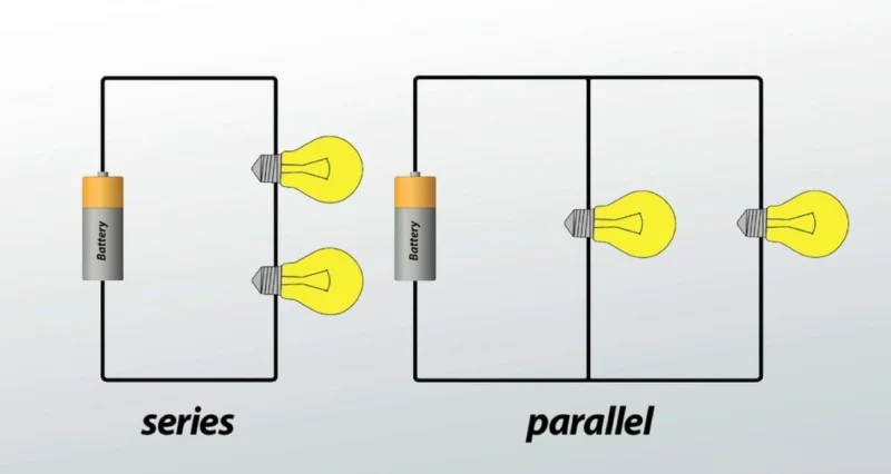
Κυκλώματα ΣειράςΤα εξαρτήματα συνδέονται από άκρο σε άκρο σε μία μόνο διαδρομή. Το ίδιο ηλεκτρικό ρεύμα ρέει μέσω όλων των εξαρτημάτων, αλλά η τάση κατανέμεται σε κάθε εξάρτημα με βάση την αντίστασή του.
Παράλληλα ΚυκλώματαΤα εξαρτήματα συνδέονται σε κοινά σημεία σύνδεσης, δημιουργώντας πολλαπλές διαδρομές για το ρεύμα. Κάθε εξάρτημα λαμβάνει την ίδια τάση, αλλά το συνολικό ρεύμα κατανέμεται μεταξύ των διαφορετικών κλάδων.
Η ΣυμπέρασμαΣε κυκλώματα σε σειρά, τα εξαρτήματα εξαρτώνται το ένα από το άλλο (αν κάποιο χαλάσει, όλα σταματούν να λειτουργούν). Σε παράλληλα κυκλώματα, τα εξαρτήματα λειτουργούν ανεξάρτητα (αν κάποιο χαλάσει, τα άλλα συνεχίζουν να λειτουργούν κανονικά).
Τι είναι τα κυκλώματα σειράς; [Ορισμός και βασικά στοιχεία]
Πώς λειτουργούν τα κυκλώματα σειράς
A κύκλωμα σειράς Συνδέει τα ηλεκτρικά εξαρτήματα από άκρο σε άκρο, σχηματίζοντας μια ενιαία συνεχή διαδρομή για τη ροή του ηλεκτρικού ρεύματος. Σκεφτείτε το σαν αυτοκίνητα που ταξιδεύουν σε έναν ορεινό δρόμο μίας λωρίδας – κάθε αυτοκίνητο πρέπει να ακολουθεί την ίδια διαδρομή και αν υπάρχει κάποιο εμπόδιο οπουδήποτε, όλη η κυκλοφορία σταματά.
Σε ηλεκτρικούς όρους, αυτό σημαίνει:
- Ρεύμα ρέει μέσα από κάθε εξάρτημα το ένα μετά το άλλο
- Η ίδια ποσότητα ρεύματος διέρχεται από κάθε εξάρτημα
- Εάν κάποιο εξάρτημα παρουσιάσει βλάβη ή αφαιρεθεί, ολόκληρο το κύκλωμα σταματά να λειτουργεί.
- Τα εξαρτήματα δεν μπορούν να ελεγχθούν ανεξάρτητα
Βασικά χαρακτηριστικά των κυκλωμάτων σειράς
Τρέχουσα ΣυμπεριφοράΤο πιο σημαντικό χαρακτηριστικό των κυκλωμάτων σε σειρά είναι ότι το ρεύμα παραμένει σταθερό σε όλο το κύκλωμαΕίτε μετρήσετε το ρεύμα πριν από το πρώτο στοιχείο είτε μετά το τελευταίο, θα λάβετε την ίδια ένδειξη. Αυτό συμβαίνει επειδή υπάρχει μόνο μία διαδρομή για να ακολουθήσουν τα ηλεκτρόνια.
Κατανομή τάσηςΣε αντίθεση με το ρεύμα, η τάση σε ένα κύκλωμα σε σειρά διαιρείται σε κάθε στοιχείοΑν έχετε μια μπαταρία 12 βολτ που τροφοδοτεί τρεις πανομοιότυπους λαμπτήρες σε σειρά, κάθε λαμπτήρας λαμβάνει 4 βολτ. Οι πτώσεις τάσης σε κάθε εξάρτημα αθροίζονται και ισούται με την τάση της πηγής – μια αρχή που είναι κρίσιμη για τον σωστό σχεδιασμό κυκλώματος.
Επιδράσεις ΑντίστασηςΣε κυκλώματα σειράς, Η συνολική αντίσταση ισούται με το άθροισμα όλων των επιμέρους αντιστάσεωνΗ προσθήκη περισσότερων εξαρτημάτων αυξάνει τη συνολική αντίσταση, γεγονός που μειώνει τη ροή ρεύματος σε ολόκληρο το κύκλωμα. Αυτός είναι ο λόγος για τον οποίο η προσθήκη περισσότερων φώτων σε ένα κύκλωμα σε σειρά μειώνει τη φωτεινότητα όλων των φώτων.
Επιχείρηση Όλα-ή-ΤίποταΊσως το πιο αξιοσημείωτο χαρακτηριστικό είναι ότι τα κυκλώματα σε σειρά λειτουργούν με βάση την αρχή "όλα ή τίποτα". Όταν ανοίγετε τον διακόπτη, όλα τα εξαρτήματα ενεργοποιούνται μαζί. Όταν ένα εξάρτημα παρουσιάσει βλάβη, όλα σταματούν να λειτουργούν.
Παραδείγματα κυκλωμάτων σειράς που βλέπετε καθημερινά
Χριστουγεννιάτικα φωτάκια σε κορδόνι (παραδοσιακό στυλ)Οι παλαιότερες σειρές χριστουγεννιάτικων φωτιστικών χρησιμοποιούν σειριακά κυκλώματα. Όταν καεί μία λάμπα, ολόκληρη η σειρά σβήνει επειδή το κύκλωμα είναι σπασμένο. Τα σύγχρονα χριστουγεννιάτικα φωτιστικά συχνά περιλαμβάνουν μηχανισμούς παράκαμψης ή χρησιμοποιούν παράλληλα κυκλώματα για να αποφευχθεί αυτό το πρόβλημα.
Φακοί με πολλαπλές μπαταρίεςΠολλοί φακοί στοιβάζουν μπαταρίες από άκρο σε άκρο σε σειρά για να αυξήσουν τη συνολική τάση. Δύο μπαταρίες AA 1,5 βολτ σε σειρά παρέχουν 3 βολτ για να τροφοδοτήσουν μια φωτεινότερη λάμπα από ό,τι θα μπορούσε να διαχειριστεί μια μόνο μπαταρία.
Συστήματα ασφαλείας αυτοκινήτουΟι αισθητήρες συναγερμού οχημάτων γύρω από πόρτες και παράθυρα είναι συχνά συνδεδεμένοι σε σειρά. Εάν ανοίξει κάποια πόρτα ή παράθυρο (διακόπτοντας το κύκλωμα), ο συναγερμός ανιχνεύει το ανοιχτό κύκλωμα και ενεργοποιεί το σύστημα προειδοποίησης.
Ηλεκτρικοί διακόπτες και ασφάλειεςΑυτές οι συσκευές ασφαλείας τοποθετούνται σκόπιμα σε σειρά με τα κυκλώματα που προστατεύουν. Όταν καεί μια ασφάλεια ή ανοίξει ένας διακόπτης, διακόπτεται το κύκλωμα σειράς και διακόπτεται η ροή ρεύματος για την αποφυγή ζημιάς ή την παροχή ελέγχου.
Τι είναι τα παράλληλα κυκλώματα; [Ορισμός και βασικά στοιχεία]
Πώς λειτουργούν τα παράλληλα κυκλώματα
A παράλληλο κύκλωμα Συνδέει εξαρτήματα σε κοινά σημεία σύνδεσης, δημιουργώντας πολλαπλές διαδρομές για τη ροή του ηλεκτρικού ρεύματος. Φανταστείτε έναν αυτοκινητόδρομο με πολλαπλές λωρίδες κυκλοφορίας – αν μία λωρίδα είναι μπλοκαρισμένη, η κυκλοφορία μπορεί να συνεχίσει να ρέει μέσω των άλλων λωρίδων. Κάθε λωρίδα λειτουργεί ανεξάρτητα.
Σε ηλεκτρικούς όρους, αυτό σημαίνει:
- Το ρεύμα έχει πολλαπλές διαδρομές για να διανύσει
- Κάθε στοιχείο λειτουργεί ανεξάρτητα
- Τα εξαρτήματα μπορούν να ελέγχονται ξεχωριστά
- Εάν ένα εξάρτημα παρουσιάσει βλάβη, τα υπόλοιπα συνεχίζουν να λειτουργούν κανονικά
Βασικά χαρακτηριστικά των παράλληλων κυκλωμάτων
Συνέπεια τάσηςΤο καθοριστικό χαρακτηριστικό των παράλληλων κυκλωμάτων είναι ότι κάθε εξάρτημα λαμβάνει την ίδια τάσηΕίτε συνδέσετε μία συσκευή είτε δέκα συσκευές παράλληλα, η καθεμία λαμβάνει την πλήρη τάση πηγής. Αυτός είναι ο λόγος για τον οποίο όλες οι πρίζες στο σπίτι σας παρέχουν τα ίδια 120 βολτ (στις ΗΠΑ) ανεξάρτητα από το πόσες συσκευές συνδέετε.
Τρέχουσα ΔιαίρεσηΕνώ η τάση παραμένει σταθερή, τρέχοντα χάσματα μεταξύ των διαφόρων κλάδωνΚάθε κλάδος τραβάει μόνο το ρεύμα που χρειάζεται με βάση την αντίστασή του. Το συνολικό ρεύμα από την πηγή ισούται με το άθροισμα όλων των ρευμάτων των κλάδων - όπως το νερό που ρέει μέσα από πολλαπλούς σωλήνες διαφορετικών μεγεθών.
Συμπεριφορά Αντίστασης: Αντιφατικά, Η προσθήκη περισσότερων εξαρτημάτων παράλληλα μειώνει στην πραγματικότητα τη συνολική αντίσταση του κυκλώματοςΑυτό συμβαίνει επειδή παρέχετε περισσότερες διαδρομές για τη ροή του ρεύματος, διευκολύνοντας την ολοκλήρωση του κυκλώματος από το ηλεκτρικό ρεύμα. Είναι σαν να προσθέτετε περισσότερες λωρίδες στα ταμεία σε ένα κατάστημα - περισσότερες λωρίδες σημαίνουν λιγότερο χρόνο αναμονής.
Ανεξάρτητη ΛειτουργίαΚάθε κλάδος ενός παράλληλου κυκλώματος λειτουργεί ανεξάρτητα. Μπορείτε να ενεργοποιείτε και να απενεργοποιείτε συσκευές χωρίς να επηρεάζετε άλλες και, εάν μία συσκευή παρουσιάσει βλάβη, οι υπόλοιπες συνεχίζουν να λειτουργούν κανονικά.
Παραδείγματα παράλληλων κυκλωμάτων στο σπίτι σας
Οικιακές ηλεκτρικές πρίζεςΚάθε πρίζα στο σπίτι σας είναι συνδεδεμένη παράλληλα με τον κύριο ηλεκτρικό πίνακα. Αυτό σας επιτρέπει να συνδέετε τις συσκευές ανεξάρτητα – η ενεργοποίηση του ψυγείου σας δεν επηρεάζει τον υπολογιστή σας και, αν χαλάσει η τοστιέρα σας, η καφετιέρα σας εξακολουθεί να λειτουργεί.
Φωτισμός αυτοκινήτωνΟι προβολείς, τα πίσω φώτα και τα εσωτερικά φώτα του αυτοκινήτου σας είναι συνδεδεμένα παράλληλα. Μπορείτε να τα ελέγχετε ανεξάρτητα με διαφορετικούς διακόπτες και, αν καεί μία λάμπα, οι άλλες συνεχίζουν να παρέχουν φωτισμό για ασφάλεια.
Στοιχεία ΥπολογιστήΜέσα στις ηλεκτρονικές συσκευές, εξαρτήματα όπως τα τσιπ μνήμης και οι επεξεργαστές συνδέονται παράλληλα για να διασφαλιστεί ότι όλα λαμβάνουν σταθερή τάση για αξιόπιστη λειτουργία.
Κυκλώματα Φωτισμού ΣπιτιούΟ σύγχρονος φωτισμός κατοικιών χρησιμοποιεί παράλληλα κυκλώματα, ώστε να μπορείτε να ελέγχετε διαφορετικά δωμάτια ανεξάρτητα. Κάθε διακόπτης φωτισμού ελέγχει τον δικό του κλάδο χωρίς να επηρεάζει τα φώτα σε άλλα δωμάτια.
Κυκλώματα σε σειρά έναντι παράλληλων κυκλωμάτων: Σύγκριση μεταξύ τους
| Όψη | Κυκλώματα Σειράς | Παράλληλα Κυκλώματα |
|---|---|---|
| Ροή ρεύματος | Το ίδιο σε όλα τα εξαρτήματα | Διαιρεί μεταξύ των κλάδων |
| Τάση | Διαιρεί τα στοιχεία | Ίδιο σε όλα τα εξαρτήματα |
| Συνολική Αντίσταση | Άθροισμα μεμονωμένων αντιστάσεων | Μικρότερη από την ελάχιστη μεμονωμένη αντίσταση |
| Έλεγχος εξαρτημάτων | Όλα τα εξαρτήματα μαζί | Ανεξάρτητος έλεγχος εξαρτημάτων |
| Βλάβη εξαρτήματος | Ολόκληρο το κύκλωμα αποτυγχάνει | Άλλα εξαρτήματα συνεχίζουν να λειτουργούν |
| Φορτίο πηγής ισχύος | Αυξάνεται με περισσότερα εξαρτήματα | Αυξάνεται με περισσότερα εξαρτήματα |
| Πολυπλοκότητα καλωδίωσης | Απλό, λιγότερες συνδέσεις | Πιο σύνθετο, περισσότερες συνδέσεις |
| Κόστος | Γενικά χαμηλότερο | Γενικά υψηλότερο |
| Αξιοπιστία | Κάτω (αστοχία ενός σημείου) | Υψηλότερο (πλεονάζουσες διαδρομές) |
| Εφαρμογές | Απλοί έλεγχοι, διαίρεση τάσης | Οικιακή καλωδίωση, ανεξάρτητες συσκευές |
Συμπεριφορά τάσης: Γιατί έχει σημασία
Κυκλώματα σε σειρά: Η τάση μειώνεται σε κάθε εξάρτημα με βάση την αντίστασή του. Αυτή η διαίρεση τάσης είναι χρήσιμη όταν χρειάζεστε διαφορετικά επίπεδα τάσης για διαφορετικά εξαρτήματα. Για παράδειγμα, εάν χρειάζεται να τροφοδοτήσετε μια συσκευή 6 βολτ από μια μπαταρία 12 βολτ, θα μπορούσατε να προσθέσετε μια αντίσταση σε σειρά για να μειώσετε τα επιπλέον 6 βολτ.
Σε παράλληλα κυκλώματαΚάθε εξάρτημα λαμβάνει την πλήρη τάση πηγής, εξασφαλίζοντας σταθερή απόδοση. Αυτό είναι απαραίτητο για συσκευές που χρειάζονται συγκεκριμένες τάσεις για να λειτουργήσουν σωστά. Ο φορτιστής του smartphone σας χρειάζεται ακριβώς τη σωστή τάση – πολύ μικρή και δεν θα φορτίσει, πολύ μεγάλη και θα μπορούσε να καταστραφεί.
Τρέχοντα πρότυπα ροής
Ροή ρεύματος σειράςΤο ρεύμα δεν έχει άλλη επιλογή από το να ρέει μέσα από κάθε εξάρτημα διαδοχικά. Αυτό καθιστά τη μέτρηση ρεύματος απλή (ίδια παντού), αλλά σημαίνει ότι το πιο αδύναμο εξάρτημα περιορίζει την απόδοση ολόκληρου του κυκλώματος.
Παράλληλη ροή ρεύματος: Το ρεύμα διαιρείται με βάση την αντίσταση κάθε κλάδου, ακολουθώντας την πορεία της ελάχιστης αντίστασης. Οι κλάδοι χαμηλής αντίστασης καταναλώνουν περισσότερο ρεύμα, ενώ οι κλάδοι υψηλής αντίστασης καταναλώνουν λιγότερο. Αυτό επιτρέπει σε συσκευές με διαφορετικές ανάγκες ισχύος να μοιράζονται το ίδιο κύκλωμα.
Υπολογισμοί αντίστασης απλοί
Αντίσταση σειράς: Απλώς προσθέστε τα
- Συνολική Αντίσταση = R₁ + R₂ + R₃ + …
- Παράδειγμα: 10Ω + 20Ω + 30Ω = 60Ω συνολικά
Παράλληλη ΑντίστασηΧρησιμοποιήστε τον αντίστροφο τύπο
- 1/Συνολική Αντίσταση = 1/R₁ + 1/R₂ + 1/R₃ + …
- Παράδειγμα: Δύο αντιστάσεις 10Ω παράλληλα = 5Ω συνολικά
- Γρήγορη συμβουλή: Για πανομοιότυπες αντιστάσεις, διαιρέστε με τον αριθμό των αντιστάσεων
Εφαρμογές στον Πραγματικό Κόσμο: Όπου Κάθε Τύπος Κυκλώματος Λάμπει
Γιατί χρησιμοποιούνται κυκλώματα σειράς
Εφαρμογές ελέγχου τάσης: Τα κυκλώματα σε σειρά υπερέχουν όταν χρειάζεται να δημιουργήσετε συγκεκριμένα επίπεδα τάσης. Μπαταρίες για ηλεκτρικά εργαλεία συχνά συνδέουν στοιχεία σε σειρά για να επιτύχουν υψηλότερες τάσεις – τέσσερα στοιχεία λιθίου 3,7V σε σειρά δημιουργούν μια μπαταρία 14,8V.
Συστήματα Ασφάλειας και ΕλέγχουΤα κυκλώματα σε σειρά παρέχουν εξαιρετικά χαρακτηριστικά ασφαλείας. Εάν κάποιος αισθητήρας σε ένα σύστημα ασφαλείας παρουσιάσει βλάβη (αισθητήρας πόρτας, αισθητήρας παραθύρου, ανιχνευτής κίνησης), το ανοιχτό κύκλωμα ειδοποιεί αμέσως το σύστημα. Αυτός ο σχεδιασμός "ασφάλειας" διασφαλίζει ότι τα προβλήματα εντοπίζονται γρήγορα.
Οικονομικά Αποδοτικές ΛύσειςΓια απλές εφαρμογές όπου όλα τα εξαρτήματα πρέπει να λειτουργούν μαζί, τα κυκλώματα σε σειρά ελαχιστοποιούν το κόστος καλωδίωσης και εξαρτημάτων. Ένας μόνο διακόπτης μπορεί να ελέγχει πολλαπλά φώτα ή συσκευές ταυτόχρονα.
Όριο ρεύματοςΟι αντιστάσεις σε σειρά χρησιμοποιούνται συνήθως για τον περιορισμό του ρεύματος σε ευαίσθητα εξαρτήματα όπως τα LED, προστατεύοντάς τα από ζημιές και διασφαλίζοντας παράλληλα την ορθή λειτουργία τους.
Γιατί τα παράλληλα κυκλώματα κυριαρχούν στην οικιακή καλωδίωση
Ανεξάρτητος έλεγχος συσκευήςΗ παράλληλη καλωδίωση επιτρέπει την ανεξάρτητη λειτουργία των ηλεκτρικών συσκευών. Μπορείτε να λειτουργήσετε το πλυντήριο πιάτων σας ενώ ο υπολογιστής σας είναι απενεργοποιημένος και καμία από τις δύο δεν επηρεάζει την απόδοση της άλλης.
Σταθερή απόδοση συσκευήςΚάθε συσκευή λαμβάνει την πλήρη τάση γραμμής, εξασφαλίζοντας βέλτιστη απόδοση. Το ψυγείο σας λαμβάνει τα ίδια 120V ανεξάρτητα από το αν χρησιμοποιείτε το κλιματιστικό σας ή όχι.
Αξιοπιστία συστήματοςΕάν μια συσκευή παρουσιάσει βλάβη, οι άλλες συνεχίζουν να λειτουργούν. Όταν καεί μια λάμπα, τα άλλα φώτα σας παραμένουν αναμμένα. Αυτή η πλεονάζουσα λειτουργία είναι ζωτικής σημασίας για κρίσιμα συστήματα όπως ο φωτισμός έκτακτης ανάγκης και ο εξοπλισμός ασφαλείας.
ΕπεκτασιμότηταΜπορείτε να προσθέσετε περισσότερες συσκευές σε παράλληλα κυκλώματα χωρίς να επηρεάσετε σημαντικά τις υπάρχουσες συσκευές (εντός των ορίων χωρητικότητας του κυκλώματος). Αυτή η ευελιξία καθιστά την παράλληλη καλωδίωση ιδανική για επεκτάσιμα συστήματα.
Σειριακά-Παράλληλοι Συνδυασμοί σε Πολύπλοκα Συστήματα
Τα περισσότερα ηλεκτρικά συστήματα στον πραγματικό κόσμο συνδυάζουν τόσο σειριακά όσο και παράλληλα στοιχεία για βελτιστοποίηση της απόδοσης, του κόστους και της αξιοπιστίας:
Ηλεκτρικά Συστήματα ΑυτοκινήτωνΤα αυτοκίνητα χρησιμοποιούν σειριακά κυκλώματα για ορισμένα χειριστήρια (όπως αλυσίδες αισθητήρων) ενώ χρησιμοποιούν παράλληλα κυκλώματα για φώτα και αξεσουάρ. Το κύκλωμα εκκίνησης μπορεί να έχει εξαρτήματα σε σειρά για ασφάλεια, ενώ το σύστημα φωτισμού χρησιμοποιεί παράλληλα κυκλώματα για ανεξάρτητη λειτουργία.
Ηλεκτρονικά είδη ευρείας κατανάλωσηςΗ μπαταρία του φορητού υπολογιστή σας ενδέχεται να έχει στοιχεία συνδεδεμένα τόσο σε σειρά (για τάση) όσο και παράλληλα (για χωρητικότητα). Το κύκλωμα φόρτισης χρησιμοποιεί στοιχεία σε σειρά για ρύθμιση τάσης και παράλληλα στοιχεία για πλεονασμό.
Ηλεκτρικοί Πίνακες ΣπιτιούΟι διακόπτες κυκλώματος είναι συνδεδεμένοι σε σειρά με τα αντίστοιχα κυκλώματά τους (για ασφάλεια), ενώ οι μεμονωμένες πρίζες σε κάθε κύκλωμα είναι συνδεδεμένες παράλληλα (για ανεξάρτητη λειτουργία).
Πώς να αναγνωρίσετε κυκλώματα σειράς έναντι παράλληλων κυκλωμάτων [Πρακτικός οδηγός]
Μέθοδοι Οπτικής Αναγνώρισης
Ακολουθήστε την τρέχουσα διαδρομήΗ πιο αξιόπιστη μέθοδος είναι η ανίχνευση της διαδρομής που πρέπει να ακολουθήσει το ρεύμα:
- Σειρά: Μόνο μία πιθανή διαδρομή από το θετικό στο αρνητικό τερματικό
- ΠαράλληλοΠολλαπλές διαδρομές μεταξύ των ίδιων δύο σημείων σύνδεσης
Μέτρηση σημείων σύνδεσης:
- ΣειράΚάθε στοιχείο συνδέεται με ακριβώς δύο άλλα (εκτός από το πρώτο και το τελευταίο)
- ΠαράλληλοΤα εξαρτήματα μοιράζονται κοινά σημεία σύνδεσης, δημιουργώντας συνδέσεις "Τ" ή "Υ"
Αναζητήστε διακλάδωση:
- ΣειράΤα εξαρτήματα σχηματίζουν μια ενιαία αλυσίδα
- Παράλληλο: Η τρέχουσα διαδρομή διακλαδώνεται και επανασυνδέεται
Συμπεριφορά διακόπτη:
- ΣειράΈνας διακόπτης ελέγχει όλα τα εξαρτήματα
- ΠαράλληλοΚάθε κλάδος μπορεί να έχει ανεξάρτητους διακόπτες
Δοκιμή με πολύμετρο
Μέθοδος δοκιμής τάσης:
- Αναγνώριση ΣειράςΜετρήστε την τάση σε κάθε εξάρτημα. Σε κυκλώματα σε σειρά, οι τάσεις θα αθροίζονται στην τάση πηγής.
- Παράλληλη ΤαυτοποίησηΜετρήστε την τάση σε κάθε εξάρτημα. Σε παράλληλα κυκλώματα, όλα τα εξαρτήματα εμφανίζουν την ίδια τάση.
Τρέχουσα μέθοδος δοκιμής:
- Αναγνώριση ΣειράςΟι μετρήσεις ρεύματος θα είναι ίδιες σε οποιοδήποτε σημείο του κυκλώματος.
- Παράλληλη ΤαυτοποίησηΟι μετρήσεις ρεύματος θα διαφέρουν μεταξύ των κλάδων, αλλά το άθροισμα είναι το συνολικό ρεύμα.
Μέθοδος δοκιμής αντοχής:
- Απενεργοποιήστε πλήρως το κύκλωμα
- ΣειράΗ συνολική αντίσταση ισούται με το άθροισμα των αντιστάσεων των επιμέρους συστατικών
- ΠαράλληλοΗ συνολική αντίσταση είναι μικρότερη από τη μικρότερη μεμονωμένη αντίσταση
Προφυλάξεις ασφαλείας:
- Πάντα να απενεργοποιείτε την παροχή ρεύματος πριν συνδέσετε τους μετρητές για μέτρηση ρεύματος
- Χρησιμοποιήστε κατάλληλα εύρη τάσης και ρεύματος
- Ποτέ μην μετράτε αντίσταση σε κυκλώματα με τροφοδοσία ρεύματος.
- Ελέγξτε ξανά τις συνδέσεις πριν από την τροφοδοσία ρεύματος
Συνήθη σενάρια αντιμετώπισης προβλημάτων
Όταν ένα στοιχείο επηρεάζει άλλα (Υποδεικνύει Σειρά):
- Μία λάμπα καίγεται, όλες οι λάμπες σβήνουν
- Μία συσκευή παρουσιάζει βλάβη, ολόκληρο το κύκλωμα σταματά να λειτουργεί
- Η προσθήκη περισσότερων συσκευών μειώνει τη φωτεινότητα ή μειώνει την ένταση του ήχου σε όλες τις συσκευές.
Όταν τα εξαρτήματα λειτουργούν ανεξάρτητα (Υποδεικνύει Παράλληλο):
- Οι μεμονωμένες συσκευές μπορούν να ελέγχονται ξεχωριστά
- Η βλάβη μιας συσκευής δεν επηρεάζει τις άλλες
- Κάθε συσκευή διατηρεί σταθερή απόδοση ανεξάρτητα από τις άλλες
Αναγνώριση μικτών κυκλωμάτων:
- Ορισμένα εξαρτήματα λειτουργούν ανεξάρτητα (παράλληλα τμήματα)
- Ορισμένα στοιχεία επηρεάζουν το ένα το άλλο (τμήματα σειράς)
- Απαιτείται προσεκτική ανάλυση κάθε τμήματος του κυκλώματος
Ανάλυση πλεονεκτημάτων και μειονεκτημάτων
Πλεονεκτήματα και μειονεκτήματα κυκλώματος σειράς
Πλεονεκτήματα:
- Απλότητα: Απαιτείται ελάχιστη καλωδίωση και συνδέσεις
- Οικονομικά αποδοτικόΛιγότερα εξαρτήματα και απλούστερη εγκατάσταση
- Ακριβής έλεγχος τάσηςΕύκολη δημιουργία συγκεκριμένων πτώσεων τάσης
- Ομοιόμορφο ρεύμα: Το ίδιο ρεύμα που διαπερνά όλα τα εξαρτήματα απλοποιεί τους υπολογισμούς
- Εύκολη μέτρηση ρεύματος: Το ρεύμα είναι ίδιο σε όλο το κύκλωμα
Μειονεκτήματα:
- Μοναδικό Σημείο Αποτυχίας: Η βλάβη ενός εξαρτήματος σταματάει ολόκληρο το κύκλωμα
- Πτώσεις τάσηςΗ προσθήκη εξαρτημάτων μειώνει την τάση σε κάθε συσκευή
- Χωρίς ανεξάρτητο έλεγχοΔεν είναι δυνατός ο ξεχωριστός έλεγχος των εξαρτημάτων
- Περιορισμένη ευελιξίαΔύσκολη τροποποίηση ή επέκταση
- Τρέχοντες περιορισμοίΌλα τα εξαρτήματα πρέπει να διαχειρίζονται το ίδιο ρεύμα
Πλεονεκτήματα και μειονεκτήματα παράλληλου κυκλώματος
Πλεονεκτήματα:
- Ανεξάρτητη Λειτουργία: Κάθε συσκευή μπορεί να ελεγχθεί ξεχωριστά
- ΑξιοπιστίαΟι βλάβες των εξαρτημάτων δεν επηρεάζουν άλλες συσκευές
- Συνεπής τάσηΚάθε συσκευή λαμβάνει πλήρη τάση πηγής
- ΕπεκτασιμότηταΕύκολη προσθήκη περισσότερων συσκευών (εντός ορίων)
- Ευέλικτο σύστημα ελέγχου: Μπορεί να χρησιμοποιήσει μεμονωμένους διακόπτες για κάθε κλάδο
Μειονεκτήματα:
- ΠολυπλοκότηταΑπαιτούνται περισσότερες καλωδιώσεις και συνδέσεις
- Υψηλότερο κόστοςΠερισσότερα υλικά και εργασία για την εγκατάσταση
- Τρέχουσα προσθήκη: Το συνολικό ρεύμα αυξάνεται με κάθε επιπλέον συσκευή
- Εξισορρόπηση φορτίουΠρέπει να διασφαλιστεί ότι το συνολικό ρεύμα δεν υπερβαίνει την χωρητικότητα της πηγής
- Αντιμετώπιση προβλημάτων πολυπλοκότηταςΠερισσότερα κυκλώματα για διάγνωση και συντήρηση
Συνηθισμένα λάθη και συμβουλές αντιμετώπισης προβλημάτων
Λάθη σχεδιασμού που πρέπει να αποφεύγετε
Σύγχυση τάσης και ρεύματος:
- ΛάθοςΥποθέτοντας ότι όλα τα εξαρτήματα χρειάζονται το ίδιο ρεύμα σε παράλληλα κυκλώματα
- ΛύσηΝα θυμάστε ότι το ρεύμα διαιρείται ενώ η τάση παραμένει σταθερή
Εποπτείες Αξιολόγησης Στοιχείων:
- ΛάθοςΧρήση εξαρτημάτων με ονομαστική τιμή για διαφορετικά ρεύματα σε κυκλώματα σειράς
- ΛύσηΒεβαιωθείτε ότι όλα τα εξαρτήματα της σειράς μπορούν να διαχειριστούν το ρεύμα κυκλώματος
Σφάλματα κυκλώματος ασφαλείας:
- ΛάθοςΤοποθέτηση διατάξεων ασφαλείας (ασφάλειες, διακόπτες) παράλληλα αντί για σε σειρά
- ΛύσηΟι συσκευές ασφαλείας πρέπει να είναι συνδεδεμένες σε σειρά για να διακόπτουν τη ροή ρεύματος
Σφάλματα υπολογισμού ισχύος:
- ΛάθοςΥποεκτίμηση της συνολικής κατανάλωσης ισχύος σε παράλληλα κυκλώματα
- Λύση: Υπολογίστε την ισχύ για κάθε κλάδο ξεχωριστά και στη συνέχεια αθροίστε για το σύνολο
Αντιμετώπιση προβλημάτων κυκλωμάτων σειράς
Πλήρης βλάβη κυκλώματος:
- Ελέγξτε για ανοιχτά κυκλώματα (σπασμένες συνδέσεις, καμένες ασφάλειες)
- Ελέγξτε κάθε εξάρτημα ξεχωριστά για συνέχεια
- Επαληθεύστε την τάση και την ισχύ της πηγής ρεύματος
- Αναζητήστε διαβρωμένες ή χαλαρές συνδέσεις
Προβλήματα μειωμένης απόδοσης:
- Μετρήστε τις πτώσεις τάσης σε κάθε εξάρτημα
- Ελέγξτε για συνδέσεις υψηλής αντίστασης
- Επαληθεύστε ότι οι προδιαγραφές των εξαρτημάτων ταιριάζουν με τις απαιτήσεις του κυκλώματος
- Δοκιμή για αλλαγές αντίστασης που σχετίζονται με τη θερμοκρασία
Διακοπτόμενη λειτουργία:
- Ελέγξτε για χαλαρές συνδέσεις που δημιουργούν διακοπτόμενη επαφή
- Δοκιμή εξαρτημάτων υπό μεταβαλλόμενες συνθήκες θερμοκρασίας
- Επαληθεύστε την αξιοπιστία του διακόπτη και του συνδετήρα
- Αναζητήστε προβλήματα σύνδεσης που προκαλούνται από κραδασμούς
Αντιμετώπιση προβλημάτων παράλληλων κυκλωμάτων
Μεμονωμένες βλάβες υποκαταστήματος:
- Απομονώστε τον κλάδο του προβλήματος δοκιμάζοντας τον καθένα ξεχωριστά
- Ελέγξτε για ανοιχτά κυκλώματα μόνο στον διακλάδωση που έχει υποστεί βλάβη
- Επαλήθευση διακοπτών και συνδέσεων που αφορούν συγκεκριμένα υποκαταστήματα
- Δοκιμή λειτουργικότητας μεμονωμένων στοιχείων
Προβλήματα μη ισορροπημένου φορτίου:
- Μετρήστε το ρεύμα σε κάθε κλάδο για να εντοπίσετε ανισορροπίες
- Ελέγξτε για εξαρτήματα που καταναλώνουν υπερβολικό ρεύμα
- Επαληθεύστε τη σωστή τάση σε κάθε σημείο σύνδεσης διακλάδωσης
- Αναζητήστε διαφορές αντίστασης μεταξύ παράλληλων διαδρομών
Προβλήματα υπερφορτωμένου κυκλώματος:
- Υπολογίστε τη συνολική κατανάλωση ρεύματος και συγκρίνετέ την με την χωρητικότητα της πηγής
- Ελέγξτε για υπερθέρμανση στην καλωδίωση και τις συνδέσεις
- Βεβαιωθείτε ότι οι συσκευές προστασίας κυκλώματος έχουν το σωστό μέγεθος
- Σκεφτείτε την ανακατανομή φορτίων σε πολλά κυκλώματα
Ποιον τύπο κυκλώματος πρέπει να επιλέξετε;
Παράγοντες Απόφασης
Απαιτήσεις ελέγχου:
- Επιλέγω σειρά όταν όλα τα εξαρτήματα πρέπει να λειτουργούν μαζί
- Επιλέγω παράλληλο όταν απαιτείται ανεξάρτητος έλεγχος
Ανάγκες Αξιοπιστίας:
- Επιλέγω σειρά για απλές, οικονομικά αποδοτικές εφαρμογές όπου η ταυτόχρονη λειτουργία είναι αποδεκτή
- Επιλέγω παράλληλο για κρίσιμες εφαρμογές όπου η ανεξαρτησία των εξαρτημάτων είναι απαραίτητη
Απαιτήσεις τάσης:
- Επιλέγω σειρά όταν χρειάζεται να διαιρέσετε την τάση ή να δημιουργήσετε υψηλότερες τάσεις
- Επιλέγω παράλληλο όταν όλα τα εξαρτήματα χρειάζονται την ίδια τάση
Τρέχουσες Σκέψεις:
- Επιλέγω σειρά όταν ο περιορισμός ρεύματος είναι ωφέλιμος
- Επιλέγω παράλληλο όταν τα εξαρτήματα έχουν διαφορετικές τρέχουσες ανάγκες
Σχέδια επέκτασης:
- Επιλέγω σειρά για σταθερές, απλές εγκαταστάσεις
- Επιλέγω παράλληλο για συστήματα που ενδέχεται να χρειαστούν μελλοντική επέκταση
Συστάσεις ειδικά για την εφαρμογή
Έργα DIY για το σπίτι:
- ΦωτισμόςΧρήση παράλληλων κυκλωμάτων για φωτισμό δωματίου (ανεξάρτητος έλεγχος)
- Διακοσμητικά φώταΗ σειρά μπορεί να λειτουργήσει για απλές εφαρμογές όπου απαιτείται ταυτόχρονη λειτουργία
- ΠρίζεςΧρησιμοποιείτε πάντα παράλληλα κυκλώματα για την εγκατάσταση της πρίζας
- ΔιακόπτεςΧρησιμοποιήστε διακόπτες σειράς για λειτουργίες ασφαλείας και ελέγχου
Εφαρμογές στην αυτοκινητοβιομηχανία:
- ΦωτισμόςΠαράλληλα κυκλώματα για ασφάλεια (η βλάβη μιας λάμπας δεν επηρεάζει τις άλλες)
- Αισθητήρες: Κυκλώματα σειράς για συστήματα ασφαλείας (οποιαδήποτε βλάβη αισθητήρα ενεργοποιεί συναγερμό)
- Αξεσουάρ: Παράλληλα κυκλώματα για ανεξάρτητη λειτουργία
- Συστήματα φόρτισης: Σειριακά παράλληλοι συνδυασμοί για βελτιστοποίηση τάσης και χωρητικότητας
Πρωτότυπα Ηλεκτρονικών:
- Διανομή ισχύοςΠαράλληλα κυκλώματα για σταθερή παροχή τάσης
- Επεξεργασία σήματος: Κυκλώματα σε σειρά για διαίρεση τάσης και επεξεργασία σήματος
- Προστασία: Κυκλώματα σειράς για περιορισμό ρεύματος και ασφάλεια
- Σχεδιασμός με αρθρωτά στοιχεία: Παράλληλα κυκλώματα για ανεξάρτητη λειτουργία μονάδας
Βιομηχανικά Συστήματα:
- Κυκλώματα ασφαλείαςΚυκλώματα σειράς για στάσεις έκτακτης ανάγκης και μανδαλώσεις
- Διανομή ισχύοςΠαράλληλα κυκλώματα για ανεξαρτησία εξοπλισμού
- Συστήματα ΕλέγχουΣυνδυαστικά κυκλώματα για σύνθετες ανάγκες αυτοματισμού
- Παρακολούθηση: Κυκλώματα σε σειρά για αλυσίδες αισθητήρων, παράλληλα για ανεξάρτητους αισθητήρες
Συχνές Ερωτήσεις
Γιατί δεν χρησιμοποιούμε σειριακά κυκλώματα για την οικιακή καλωδίωση;
Η οικιακή καλωδίωση χρησιμοποιεί παράλληλα κυκλώματα για διάφορους κρίσιμους λόγους. Πρώτον, ανεξάρτητη λειτουργία είναι απαραίτητο – πρέπει να ανάβετε και να σβήνετε τα φώτα σε διαφορετικά δωμάτια χωρίς να επηρεάζεται το ένα το άλλο. Δεύτερον, συνέπεια τάσης διασφαλίζει ότι κάθε συσκευή λαμβάνει τα πλήρη 120V για τα οποία έχει σχεδιαστεί. Τρίτον, αξιοπιστία σημαίνει ότι όταν μια συσκευή χαλάσει, οι άλλες συνεχίζουν να λειτουργούν. Φανταστείτε όλο το σπίτι σας να σκοτεινιάζει κάθε φορά που καίγεται μια μόνο λάμπα!
Μπορείτε να συνδυάσετε σειριακή και παράλληλη σύνδεση στο ίδιο κύκλωμα;
Απολύτως! Τα περισσότερα πολύπλοκα ηλεκτρικά συστήματα χρησιμοποιούν σειριακούς-παράλληλους συνδυασμούςΓια παράδειγμα, το αυτοκίνητό σας μπορεί να έχει προβολείς που συνδέονται παράλληλα (για ανεξαρτησία) και ελέγχονται από έναν διακόπτη που συνδέεται σε σειρά (για έλεγχο). Τα οικιακά κυκλώματα χρησιμοποιούν παράλληλες πρίζες που ελέγχονται από διακόπτες κυκλώματος συνδεδεμένους σε σειρά. Αυτοί οι συνδυασμοί επιτρέπουν στους μηχανικούς να βελτιστοποιήσουν τόσο την απόδοση όσο και το κόστος.
Ποιος τύπος καταναλώνει περισσότερη ενέργεια;
Κανένας από τους δύο τύπους κυκλώματος δεν χρησιμοποιεί εγγενώς περισσότερη ισχύ – Η κατανάλωση ενέργειας εξαρτάται από τα εξαρτήματα και τον τρόπο χρήσης τουςΩστόσο, τα παράλληλα κυκλώματα φαίνεται συχνά να καταναλώνουν περισσότερη ισχύ επειδή κάθε εξάρτημα λειτουργεί σε πλήρη τάση και καταναλώνει το προβλεπόμενο ρεύμα του. Στα κυκλώματα σε σειρά, η μειωμένη τάση σε κάθε εξάρτημα συνήθως οδηγεί σε χαμηλότερη κατανάλωση ενέργειας ανά εξάρτημα.
Πώς λειτουργούν διαφορετικά τα χριστουγεννιάτικα λαμπάκια;

Παραδοσιακά χριστουγεννιάτικα φώτα Χρησιμοποιήστε κυκλώματα σε σειρά – όταν χαλάσει μία λάμπα, ολόκληρη η σειρά σβήνει. Σύγχρονα χριστουγεννιάτικα φώτα συχνά χρησιμοποιούν παράλληλα κυκλώματα ή ειδικούς μηχανισμούς παράκαμψης. Ορισμένες νεότερες σειρές χρησιμοποιούν έναν συνδυασμό: μικρές ομάδες φώτων σε σειρά, με αυτές τις ομάδες να συνδέονται παράλληλα, παρέχοντας μια ισορροπία μεταξύ κόστους και αξιοπιστίας.
Τι συμβαίνει με την αντίσταση όταν προσθέτουμε εξαρτήματα;
Αυτή είναι μια από τις πιο αντιφατικές πτυχές των κυκλωμάτων:
- Κυκλώματα σειράς: Προσθήκη στοιχείων αυξήσεις συνολική αντίσταση (σαν να προσθέτουμε εμπόδια σε μία μόνο διαδρομή)
- Παράλληλα κυκλώματα: Προσθήκη στοιχείων μειώνεται συνολική αντίσταση (όπως η προσθήκη περισσότερων διαδρομών για τη ροή του ρεύματος)
Η κατανόηση αυτής της έννοιας είναι κρίσιμη για την πρόβλεψη του τρόπου με τον οποίο θα συμπεριφερθούν τα κυκλώματα όταν τροποποιηθούν.
Συμπέρασμα
Κατανόηση της διαφορά μεταξύ σειριακών και παράλληλων κυκλωμάτων είναι θεμελιώδης για την ασφαλή και αποτελεσματική εργασία με ηλεκτρικά συστήματα. Τα κυκλώματα σε σειρά υπερέχουν σε εφαρμογές που απαιτούν απλό έλεγχο, διαίρεση τάσης ή λειτουργία χωρίς σφάλματα, ενώ τα παράλληλα κυκλώματα κυριαρχούν όπου η ανεξάρτητη λειτουργία, η αξιοπιστία και η σταθερή τάση αποτελούν προτεραιότητες.
Βασικά σημεία για πρακτική εφαρμογή:
- Κυκλώματα σειράς συνδέστε τα εξαρτήματα από άκρο σε άκρο, μοιράζοντας το ρεύμα αλλά διαιρώντας την τάση
- Παράλληλα κυκλώματα συνδέστε εξαρτήματα σε κοινά σημεία, μοιράζοντας τάση αλλά διαιρώντας το ρεύμα
- Οικιακή καλωδίωση χρησιμοποιεί παράλληλα κυκλώματα για αξιοπιστία και ανεξάρτητο έλεγχο
- Συστήματα ασφαλείας συχνά χρησιμοποιούν σειριακά κυκλώματα για ασφαλή λειτουργία από σφάλματα
- Τα περισσότερα συστήματα του πραγματικού κόσμου συνδυάστε και τους δύο τύπους για βέλτιστη απόδοση
Είτε επιλύετε προβλήματα σε ένα κύκλωμα, είτε σχεδιάζετε ένα ηλεκτρικό έργο που κάνετε μόνοι σας, είτε απλώς προσπαθείτε να κατανοήσετε πώς λειτουργούν οι ηλεκτρονικές σας συσκευές, αυτές οι βασικές έννοιες θα σας φανούν χρήσιμες. Να θυμάστε ότι η ηλεκτρική ασφάλεια πρέπει πάντα να είναι η πρώτη σας προτεραιότητα – σε περίπτωση αμφιβολίας, συμβουλευτείτε εξειδικευμένους επαγγελματίες.
Είστε έτοιμοι να εφαρμόσετε αυτές τις γνώσεις στην πράξη; Ξεκινήστε αναγνωρίζοντας τα σειριακά και παράλληλα κυκλώματα στο σπίτι σας και θα δείτε γρήγορα πώς αυτές οι έννοιες εφαρμόζονται στα ηλεκτρικά συστήματα που χρησιμοποιείτε καθημερινά.
