
If you are choosing between a latching relay και non-latching relay, one distinction decides the rest: a latching relay holds its last contact position after the control signal is removed, while a non-latching relay springs back to its default state the moment coil power disappears.
That single behavioral difference ripples through every other design consideration — energy consumption, coil heat, power-loss response, wiring complexity, fail-safe philosophy, and application fit. Understanding exactly how and why these two relay types diverge is the fastest path to a correct selection. Before diving into the comparison, it’s helpful to understand the broader context of επαφείς έναντι ρελέ in switching applications.
In short:
- Επιλέξτε έναν latching relay (bistable relay) when the circuit must remember its last state without continuous coil power.
- Επιλέξτε έναν non-latching relay (monostable relay) when the circuit must return to a defined default state whenever power is lost.
Βασικά συμπεράσματα
- A latching relay stays in its last switched position even after the coil pulse ends — no holding power required.
- A non-latching relay requires continuous coil energization to remain in its activated state.
- Latching relays excel in low-power, battery-sensitive, remote-control, and state-memory applications.
- Non-latching relays excel in simple control logic, fail-safe return behavior, and conventional industrial panels.
- The right choice depends on power budget, thermal constraints, reset behavior, control architecture, and the required response to power loss.
Latching Relay vs Non-Latching Relay: Quick Comparison Table
| Παράγοντας Επιλογής | Latching Relay | Non-Latching Relay |
|---|---|---|
| Also called | Bistable relay, keep relay, impulse relay | Monostable relay, standard relay |
| State after control power is removed | Remains in last switched position | Returns to default (de-energized) position |
| Coil power requirement | Short pulse to set or reset; zero holding power | Continuous power required for entire energized duration |
| Παραγωγή θερμότητας | Low — coil is off between switching events | Higher — coil dissipates heat continuously while energized |
| Έλεγχος πολυπλοκότητας | Higher — set/reset pulse logic or polarity reversal needed | Lower — simple on/off voltage application |
| Μηχανική διάρκεια ζωής | Typically shorter due to latching mechanism wear | Typically longer in standard designs |
| Power-loss behavior | Retains last state (memory) | Drops out to default state (auto-reset) |
| Καλύτερη εφαρμογή | Energy-saving, battery systems, smart metering, building automation, remote switching | Industrial control panels, interposing circuits, alarm logic, motor-control auxiliaries |
| Typical cost | Slightly higher per unit | Generally lower per unit |
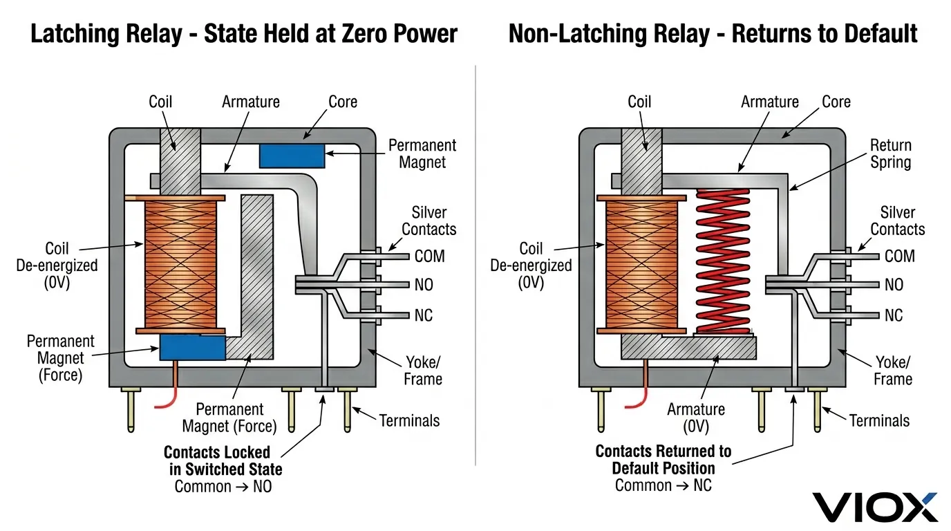
What Is a Latching Relay?
A latching relay is an electromechanical switch that remains in its last switched position even after coil power is completely removed. Once a control pulse moves the contacts to a new position, they stay there — indefinitely — until a second pulse explicitly commands them to move back.
This “positional memory” is the defining characteristic. Because the relay does not need continuous current to hold its contacts, it functions as a bistable device with two equally stable resting states: set and reset.
How a Latching Relay Works
The working principle differs slightly between single-coil and two-coil designs, but the core concept is the same: a permanent magnet or mechanical latch holds the armature in position after the coil pulse ends.
- Pulse applied — Current flows through the coil, generating a magnetic field strong enough to overcome the holding force of the existing state and move the armature.
- Contacts switch — The armature moves, opening or closing the contact set.
- Pulse removed — The coil de-energizes, but a permanent magnet (in polarized designs) or a mechanical catch (in mechanically latched designs) keeps the armature locked in its new position.
- State held at zero power — The relay remains in that position with no energy consumption whatsoever.
- Opposite pulse applied — A reverse-polarity pulse (single-coil) or a pulse on the second coil (two-coil) releases the latch and moves the armature back.
This is why a latching relay is also called a bistable relay, ένα keep relay, or an impulse relay. It has two stable positions and toggles between them only when it receives an explicit command.
Latching Relay Types: Single-Coil vs Two-Coil
Not all latching relays use the same control method. The two most common architectures are single-coil and two-coil designs, and they have meaningful differences in wiring and control logic.
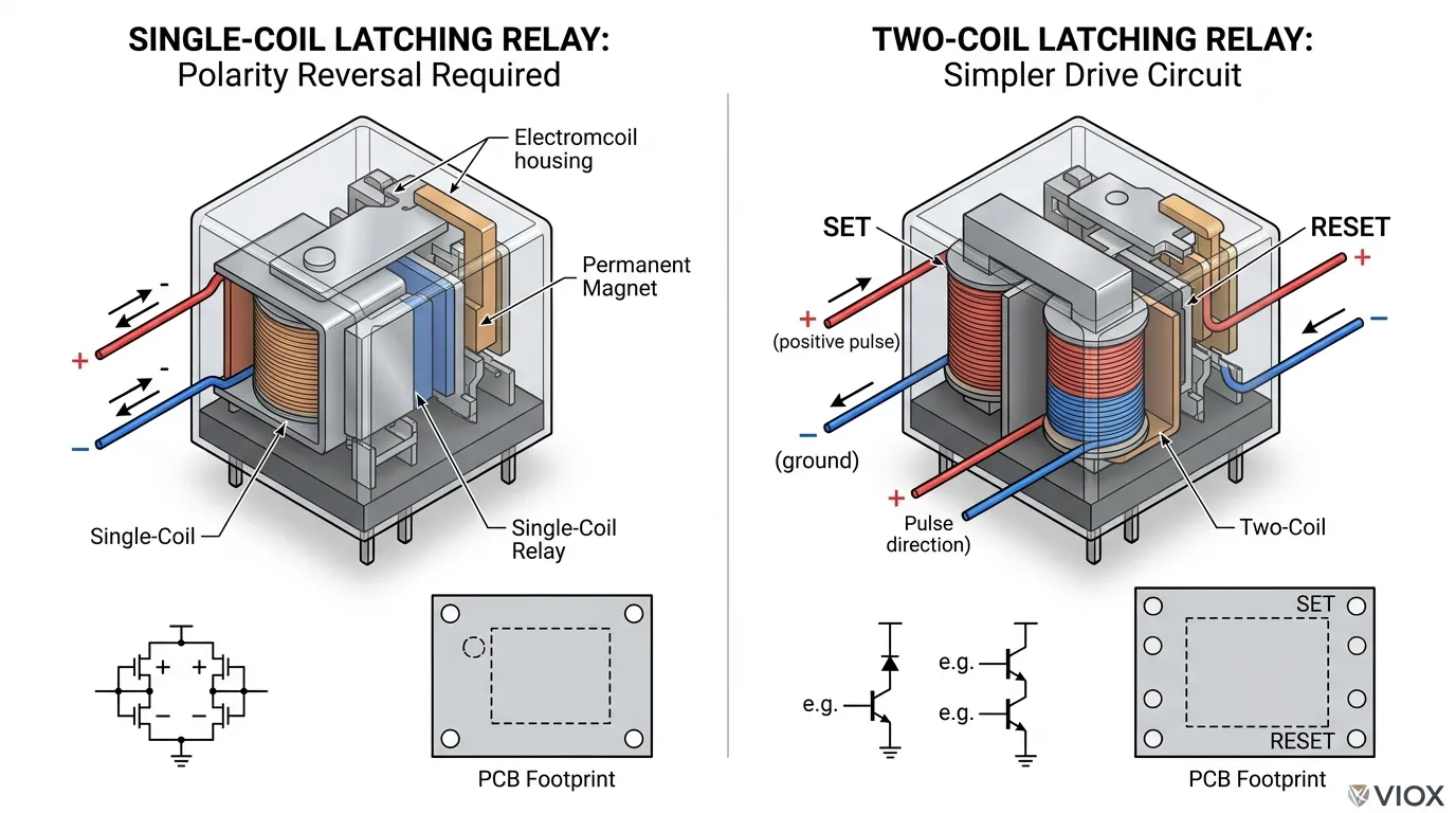
Single-Coil Latching Relay
A single-coil latching relay uses one coil for both the set and reset operations. The direction of current through the coil determines which state the relay moves to.
- To set: Apply a positive-polarity pulse to the coil.
- To reset: Apply a reverse-polarity pulse to the same coil.
This design uses fewer pins and less board space, making it popular in compact PCB layouts and consumer electronics. However, the control circuit must be capable of reversing coil polarity — which typically requires an H-bridge driver or a microcontroller output stage with polarity-switching capability.
Two-Coil Latching Relay
A two-coil latching relay has two physically separate coils: one dedicated to setting the contacts and one dedicated to resetting them.
- To set: Apply a pulse to the set coil.
- To reset: Apply a pulse to the reset coil.
This approach simplifies the drive circuit because no polarity reversal is needed — each coil only receives current in one direction. In PLC-controlled systems and industrial panel designs, two-coil latching relays are often easier to integrate because each coil can be driven by a separate discrete output.
Which Latching Relay Design Should You Choose?
| Design Factor | Single-Coil Latching Relay | Two-Coil Latching Relay |
|---|---|---|
| Pin count | Fewer (2 coil pins) | More (4 coil pins) |
| Drive circuit | Requires polarity reversal (H-bridge) | Simpler — one direction per coil |
| PCB space | Smaller footprint | Slightly larger |
| PLC integration | More complex output mapping | Easier — one output per coil |
| Κόστος | Usually lower | Usually slightly higher |
Σωστό coil suppression techniques are essential for protecting drive circuits from inductive kickback, regardless of which latching relay design you choose.
Why Engineers Choose Latching Relays
The primary motivation is almost always reduced energy consumption. Because the coil draws power only during the brief switching pulse — typically 10 to 100 milliseconds — the long-term power demand approaches zero while the relay holds its state.
Beyond energy savings, latching relays offer:
- Reduced coil heat — No sustained current means no sustained thermal dissipation, which matters in sealed enclosures and high-density layouts.
- State survival through power outages — The last contact position is preserved even during a complete loss of control power, which is critical in metering and safety-lockout applications.
- Lower demand on the power supply — Battery-powered and solar-powered systems benefit significantly from eliminating continuous coil current.
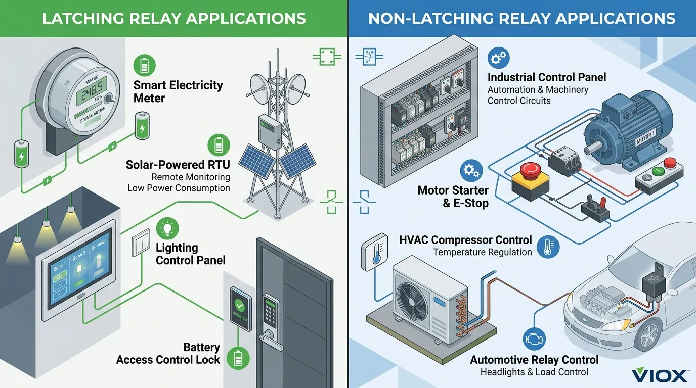
Typical latching relay applications include:
- Smart electricity, gas, and water metering
- Lighting control and dimming systems
- Building automation (HVAC valve control, motorized blinds)
- Remote power switching in telecom and utility infrastructure
- Battery-powered or energy-harvesting devices
- Security system door locks and access control
- Medical devices where state retention is required during battery changeover
For applications requiring timed switching operations in addition to state retention, consider exploring χρονικά ρελέ which can complement latching relay functionality.
What Is a Non-Latching Relay?
A non-latching relay is an electromechanical switch that changes state only while its coil remains energized. The instant coil power is removed, a return spring pushes the armature back to its default (de-energized) position.
This means a non-latching relay has only one stable state — its spring-return position. The energized state is maintained entirely by continuous current flow through the coil. Remove the current, and the contacts always return to the same known position.
This single-stable-state behavior is why non-latching relays are also called monostable relays.
How a Non-Latching Relay Works
The operating principle is straightforward:
- Coil energized — Applying voltage to the coil generates a magnetic field that attracts the armature, moving the contacts from their normal position (typically NC — normally closed) to their energized position (typically NO — normally open).
- State maintained by continuous power — As long as coil voltage is maintained, the magnetic force holds the armature against the spring force, keeping the contacts in the energized position.
- Coil de-energized — When coil voltage is removed, the magnetic field collapses and the return spring pushes the armature back to its resting position.
- Contacts return to default — The relay is now back in its normal state, exactly where it started.
There is no memory, no latch, and no ambiguity. The relay position is always a direct function of whether or not coil power is present.
Why Engineers Choose Non-Latching Relays
Non-latching relays remain the most widely used relay type across industrial, commercial, and consumer applications for several practical reasons:
- Simple control logic — One signal, one state. Apply voltage to energize; remove voltage to de-energize. No pulse timing, no polarity management, no set/reset sequencing.
- Predictable default behavior — On power loss, the relay always returns to the same known state. This inherent fail-safe characteristic is essential in many safety-critical applications.
- Straightforward wiring — A non-latching relay integrates directly with standard PLC outputs, timer contacts, pushbutton stations, and ladder logic without special driver circuits.
- Lower cost and wider availability — Non-latching relays are produced in vastly higher volumes, making them cheaper and available in more form factors, voltage ratings, and contact configurations.
- Longer mechanical life — Without a latching mechanism to wear, standard non-latching relays often achieve higher cycle counts.
Typical non-latching relay applications include:
- Interposing relays in industrial control panels
- Standard machine control logic (motor starters, solenoid drivers)
- Alarm and annunciation circuits
- Timer-controlled processes
- HVAC compressor and fan control
- Automotive accessories (headlights, wipers, horn)
- Any circuit where loss of control power should de-energize the output
In safety-critical applications like fire alarm systems, non-latching relays provide essential fail-safe behavior by automatically returning to their default state when control power is lost.
The Key Differences That Actually Affect Relay Selection
1. State Retention After Power Loss
This is the most consequential difference and should be the first question in any selection process.
A latching relay retains its last contact position through a power interruption. When control power returns, the contacts are still in whatever position they were in before the outage. This makes latching relays the natural choice for applications that require non-volatile state memory — smart meters that must keep a disconnect switch open during outages, for example, or lighting scenes that should persist through momentary power flickers.
A non-latching relay drops out immediately when control power disappears. Every power cycle starts from the same known default state. This is desirable in motor-control circuits, emergency shutdown systems, and any application where an uncontrolled or unknown state after power recovery could create a hazard.
Decision rule: If the answer to “What should happen to the output when control power is lost?” is “stay where it is,” lean toward a latching relay. If the answer is “return to a safe default,” lean toward a non-latching relay.
2. Power Consumption and Energy Efficiency
This difference becomes significant in applications with long hold times or constrained power budgets.
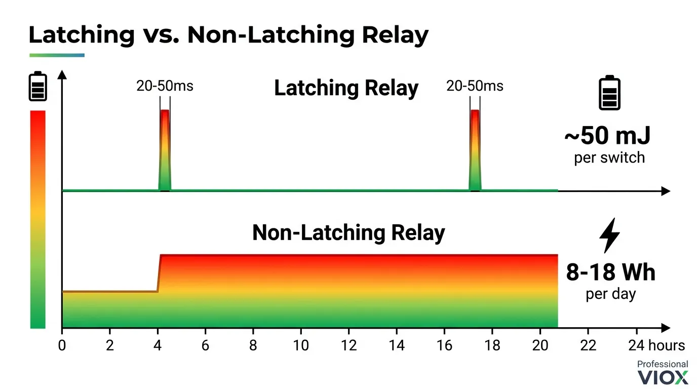
A latching relay consumes coil power only during the switching pulse. For a typical 5V latching relay, the pulse might last 20–50 ms and draw 150–200 mA — a total energy expenditure of roughly 15–50 mJ per switching event. Between events, the coil power consumption is exactly zero.
A non-latching relay consumes coil power continuously for the entire time it is held in the energized state. A typical 5V non-latching relay might draw 70–150 mA continuously. Over a 24-hour hold period, that amounts to roughly 8–18 Wh of energy — orders of magnitude more than a latching relay switching once per day.
For battery-powered systems, solar-powered remote installations, or energy-harvesting IoT devices, this difference can be the deciding factor in whether the system meets its operational lifetime target.
3. Coil Heat and Thermal Management
Non-latching relays generate continuous heat whenever they are energized. The power dissipated in the coil — typically calculated as $P = I^2 R$ or $P = V^2 / R$ — becomes thermal energy that must be managed.
In a sealed enclosure with limited airflow, multiple continuously energized non-latching relays can raise the internal temperature significantly. This is a real concern in outdoor cabinets, compact DIN-rail assemblies, and high-density PCB designs.
Latching relays largely eliminate this problem. Because the coil is de-energized between switching events, there is no sustained heat source. In thermally constrained designs, this advantage alone can justify the switch to a latching relay — even when power consumption is not a primary concern.
4. Fail-Safe and Safety Considerations
This is the selection factor where the most costly mistakes happen.
Non-latching relays are inherently fail-safe in the drop-out direction. If the coil circuit fails (broken wire, blown fuse, controller fault, power supply failure), the relay returns to its spring-loaded default position. Designers can arrange the circuit so that this default position is the safe condition — motor stopped, valve closed, heater off, alarm activated.
Latching relays do not have an inherent fail-safe direction. They stay wherever they are, regardless of what happens to the control system. If the relay was in the “output on” state when the controller failed, it remains in the “output on” state. This persistence can be valuable (smart meter disconnect) or dangerous (heater left on), depending on the application.
When selecting a latching relay for any safety-adjacent application, the design must include an independent means of forcing the relay to a safe state — a watchdog timer, a hardware safety circuit, or a redundant shutdown path.
5. Control Method, Wiring, and Drive Circuits
Non-latching relays require the simplest possible control interface: connect the coil to a switched voltage source. A PLC discrete output, a transistor, a mechanical switch, or even a simple timer contact can drive a non-latching relay directly. The control logic is one line of ladder logic or one GPIO pin.
Latching relays require more deliberate control design:
- Single-coil latching relays need polarity reversal. This typically requires an H-bridge circuit, a DPDT switch arrangement, or a microcontroller with a dual-output driver. The pulse duration must also be controlled — too short and the relay may not switch reliably; too long and the coil may overheat.
- Two-coil latching relays need two independent control signals — one for the set coil and one for the reset coil. In PLC systems, this means allocating two discrete outputs per relay instead of one. In microcontroller designs, it means two GPIO pins plus driver transistors.
Additionally, after a power-up or system initialization, the controller may not know the current state of a latching relay unless there is a position feedback mechanism (auxiliary contacts or a contact-position sensor). This state-uncertainty problem does not exist with non-latching relays, because their state is always known from the coil drive signal.
When selecting coil voltage for your application, understanding 12V vs 24V DC relay considerations can help optimize your design for power efficiency and control circuit compatibility.
6. Mechanical Lifespan and Reliability
Non-latching relays generally have a simpler internal mechanism — a coil, an armature, a spring, and contacts. With fewer moving parts and no permanent magnets or mechanical catches, they tend to achieve higher mechanical life ratings. Typical non-latching relay specifications range from 10 million to 100 million mechanical operations.
Latching relays incorporate additional components — permanent magnets (in polarized designs) or mechanical latch mechanisms — that add complexity and potential wear points. While modern latching relays are highly reliable, their rated mechanical life is often somewhat lower than equivalent non-latching designs, particularly in high-cycle applications.
For applications with very high switching frequency (hundreds or thousands of cycles per day), a non-latching relay may offer longer service life. For applications with infrequent switching (a few cycles per day or less), this difference is usually negligible.
7. Cost and Availability
Non-latching relays are manufactured in far greater volumes and enjoy broader market competition. As a result, they are generally less expensive and available in a wider range of form factors, contact configurations, coil voltages, and package styles.
Latching relays, while widely available from major manufacturers, tend to carry a modest price premium — typically 20% to 50% more than a comparable non-latching relay. In high-volume consumer products, this cost difference is significant. In low-volume industrial systems, it is usually secondary to functional requirements.
Latching Relay vs Non-Latching Relay: Detailed Behavior Comparison
| Behavior Scenario | Latching Relay | Non-Latching Relay |
|---|---|---|
| Control power lost while relay is energized | Contacts stay in energized position | Contacts return to default position |
| Control power restored after outage | Contacts remain in pre-outage position | Contacts start in default position; controller must re-energize |
| Controller resets or reboots | Contacts unchanged — controller must query or assume state | Contacts in default position — known starting state |
| Coil wire breaks | Contacts stay in last position (cannot be switched) | Contacts return to default position (fail-safe drop-out) |
| Long-duration hold (hours to months) | Zero coil power, zero heat | Continuous coil power, continuous heat |
| Rapid cycling (thousands of operations per hour) | Each cycle requires a pulse in each direction | Simply toggle coil voltage on and off |
| Battery-powered operation | Excellent — minimal energy drain | Poor — continuous drain during energized state |
When You Should Choose a Latching Relay
Choose a latching relay when the application benefits from one or more of these conditions:
- The switched state must be retained without continuous coil power. This is the primary and most common reason. If the relay will be in a given state for extended periods (minutes, hours, days, or permanently), a latching relay eliminates all holding-power waste.
- Energy consumption must be minimized. Battery-operated devices, solar-powered remote telemetry units, energy-harvesting sensors, and utility metering equipment all benefit from the near-zero standby consumption of a latching relay.
- Coil heat is a design constraint. In sealed enclosures, compact PCB assemblies, or ambient environments that are already near the relay’s thermal rating, eliminating sustained coil heating can be the difference between a reliable design and a thermally marginal one.
- The contact state must survive power outages. Smart meters, safety disconnects, and lighting control systems often require that the last commanded state persist through any interruption in control power.
- The control system is designed around set/reset or pulse-based logic. If the controller architecture already supports pulse outputs or event-driven switching, latching relays integrate naturally.
Specific Latching Relay Application Examples
- Smart metering (electricity, gas, water): The disconnect relay inside a smart meter must remain in whatever position the utility commanded — even if the meter loses power for days. A latching relay is the only practical choice.
- Lighting control and building automation: Scene controllers, occupancy-based systems, and centralized lighting panels use latching relays to maintain the lighting state between control commands without wasting energy.
- Remote telecom and utility switching: Equipment installed on cell towers, pipeline monitoring stations, or electrical substations often runs on limited power budgets with infrequent switching commands.
- Battery-backed access control: Electronic door locks and security panels use latching relays to maintain lock state during power transitions or battery replacement.
- Medical devices: Infusion pumps, patient monitors, and other devices may use latching relays to preserve valve states during battery changeover or brief power interruptions.
When You Should Choose a Non-Latching Relay
Choose a non-latching relay when the application benefits from these conditions:
- The circuit should return to a defined safe state on power loss. If the design philosophy requires that loss of control power automatically de-energizes the output — stopping a motor, closing a valve, activating an alarm — a non-latching relay provides this behavior inherently.
- Simple control logic is a priority. If the system uses basic ladder logic, simple timer contacts, manual switches, or single-output PLCs, a non-latching relay requires the least complex control interface.
- The application follows conventional industrial control practice. Most industrial control panels, machine builders, and system integrators design around non-latching relay behavior. Using the same type reduces training costs, simplifies maintenance, and aligns with established wiring standards.
- The relay will cycle frequently. In applications with high switching rates, non-latching relays typically offer better mechanical endurance and simpler timing requirements.
- Cost is a significant constraint in high-volume production. For consumer products manufactured in tens of thousands of units, the lower per-unit cost of non-latching relays can meaningfully affect the bill of materials.
Specific Non-Latching Relay Application Examples
- Motor control auxiliaries: Interposing relays between a PLC and a motor contactor should drop out when the PLC loses power, ensuring the motor stops.
- Alarm and annunciation circuits: Audible and visual alarms that must activate (or de-activate) in direct response to a control signal, and must silence when the system is de-energized.
- HVAC compressor control: Compressor contactors and fan relays that must de-energize on controller failure to prevent equipment damage.
- Automotive lighting and accessories: Headlight relays, wiper relays, and horn relays all must de-energize when the driver turns off the switch.
- Safety interlock circuits: Emergency stop systems, guard-door interlocks, and light-curtain monitor relays that must force outputs off when the safety circuit is interrupted.
Which Relay Is Better for Industrial Control Panels?
In the majority of industrial control panels, non-latching relays remain the standard choice. The reasons are practical:
- Panel designers expect relays to drop out when control power is lost.
- Maintenance technicians can determine relay state by checking coil voltage.
- Ladder logic and hardwired control circuits are built around the assumption that relay state equals coil state.
- Safety standards (such as IEC 60204-1 for machinery safety) often require that loss of control power results in a safe machine state — which aligns naturally with non-latching behavior.
Ωστόσο, latching relays are increasingly used in panel designs where:
- A memory function is required (maintaining a lighting scene, holding a process state through a brief power dip).
- Energy consumption in the panel must be reduced (large panels with dozens of continuously energized relays can generate significant heat).
- The panel serves a remote or battery-backed system where continuous coil power is impractical.
The better relay for any given panel is not the one with the more advanced mechanism — it is the one whose behavior aligns with the panel’s control philosophy and safety requirements. For panel installations, αρθρωτοί επαφείς offer similar space-saving benefits and can be selected based on similar criteria.
Συνηθισμένα λάθη επιλογής που πρέπει να αποφεύγετε
Choosing a latching relay only to save power
Power savings are real and valuable, but they must not override the requirements for fail-safe behavior, state-determinism after power-up, or simplicity of maintenance. If the application needs guaranteed drop-out on power loss, a latching relay creates a safety problem that no amount of energy savings can justify.
Choosing a non-latching relay without evaluating long-term hold time
If the relay must remain energized for hours, days, or indefinitely, the continuous coil power and resulting heat may create thermal management problems. In high-ambient-temperature environments or sealed enclosures, this oversight can lead to premature relay failure or enclosure overheating.
Ignoring power-loss behavior during the design phase
Many relay selection mistakes stem from a simple omission: the design team never explicitly defined what should happen to each output when control power is lost and subsequently restored. This question should be answered for every relay output in the system before selecting relay types.
Forgetting the drive-circuit requirements of latching relays
A single-coil latching relay cannot be driven by a simple transistor switch — it needs polarity reversal. A two-coil latching relay needs two output channels per relay. If the controller hardware does not support these requirements, the latching relay selection creates a control-system problem that was entirely avoidable. Learn how to diagnose buzzing coils and other relay failures to avoid similar issues during installation and operation.
Assuming the controller knows the latching relay’s state after power-up
Unlike a non-latching relay (whose state is always “default” at power-up), a latching relay could be in either position after a restart. The control software must either read back the contact state via auxiliary contacts, command a known state during initialization, or be designed to operate correctly regardless of the relay’s starting position. If you suspect relay failure during operation, learn how to test a relay properly to diagnose issues accurately.
Treating all latching relays as interchangeable
Single-coil and two-coil latching relays have fundamentally different wiring requirements, drive circuits, and control-logic implications. Specifying “latching relay” on a bill of materials without specifying the coil configuration can lead to procurement errors and redesign delays.
Practical Selection Checklist
Use this decision framework to guide your relay type selection:
| Ερώτηση | If Yes → Lean Toward |
|---|---|
| Must the relay keep its last state when control power is removed? | Latching relay |
| Must the circuit return to a default state when control power is lost? | Non-latching relay |
| Is low energy consumption a critical design requirement? | Latching relay |
| Is simple, conventional control wiring more important than energy savings? | Non-latching relay |
| Is coil heat a concern in a long-duty or thermally constrained application? | Latching relay |
| Is fail-safe drop-out behavior required by the safety analysis? | Non-latching relay |
| Is the system battery-powered or energy-harvesting? | Latching relay |
| Does the control system have only simple on/off outputs available? | Non-latching relay |
| Must the relay state be deterministic immediately after power-up? | Non-latching relay |
| Does the application switch infrequently but hold for long periods? | Latching relay |
Συμπέρασμα
The choice between a latching relay και non-latching relay ultimately reduces to one question: what should the relay do when the control signal goes away?
A latching relay holds its last state. It saves energy, eliminates coil heat during long hold periods, and preserves the output position through power interruptions. It is the right choice for energy-sensitive systems, state-memory applications, battery-powered devices, and remote switching installations.
A non-latching relay returns to its default state. It simplifies control logic, provides inherent fail-safe drop-out, aligns with conventional industrial practice, and ensures a known starting condition after every power cycle. It is the right choice for standard industrial control, safety-critical circuits, simple switching applications, and any system where power-loss drop-out is a requirement.
Neither type is universally superior. The better relay is the one whose natural behavior matches the functional and safety requirements of your specific application. Define what must happen on power loss first — the correct relay type will follow from that answer.
ΣΥΧΝΈΣ ΕΡΩΤΉΣΕΙΣ
What is the main difference between a latching relay and a non-latching relay?
A latching relay maintains its last contact position after the control signal is removed — it “remembers” whether it was set or reset. A non-latching relay returns to its spring-loaded default position as soon as coil power is removed. This difference in state retention is the fundamental distinction between the two types.
Is a latching relay the same as a bistable relay?
Yes. In practical engineering usage, the terms latching relay και bistable relay refer to the same device. It is called “bistable” because it has two stable resting states (set and reset), and it remains in whichever state it was last commanded to, without requiring continuous power.
Is a non-latching relay the same as a monostable relay?
Ναι. Ένα RCBO non-latching relay is commonly described as a monostable relay because it has only one stable state — its spring-return (de-energized) position. The energized state is maintained only by continuous coil current and is not independently stable.
Which relay type uses less power?
A latching relay uses dramatically less power in applications where the switched state must be maintained for extended periods. It consumes energy only during the brief switching pulse (typically 20–100 ms), while a non-latching relay consumes continuous coil power for the entire hold duration. For a relay held energized for 24 hours, the energy difference can be several orders of magnitude.
Which relay is better for fail-safe behavior?
A non-latching relay is generally better for fail-safe applications because it inherently returns to its default state when control power is lost. Designers can arrange the circuit so that this default state is the safe condition. A latching relay stays in its last position regardless of control-system status, which requires additional safety measures if fail-safe behavior is needed.
Which relay is better for battery-powered equipment?
Latching relays are strongly preferred for battery-powered systems. Because they require no holding power between switching events, they can extend battery life by orders of magnitude compared to a non-latching relay that draws continuous coil current. This makes them the standard choice in smart meters, portable instruments, and remote telemetry equipment.
Are latching relays harder to control than non-latching relays?
They can be. A non-latching relay requires only a simple on/off voltage signal. A single-coil latching relay requires polarity reversal (typically an H-bridge driver), while a two-coil latching relay requires two separate control outputs. Additionally, the control system may need to manage pulse duration and track the relay’s current state, adding software complexity.
What is the difference between a single-coil and a two-coil latching relay?
A single-coil latching relay uses one coil and switches between set and reset states by reversing the polarity of the current pulse. A two-coil latching relay uses two separate coils — one for set, one for reset — each driven with a single-polarity pulse. Two-coil designs simplify the drive circuit but require more wiring and an additional control output.
Can I use a latching relay in a safety-critical circuit?
Yes, but with additional design precautions. Because a latching relay does not automatically return to a safe state on power loss, the safety design must include an independent mechanism to force the relay to the safe position — such as a hardwired safety circuit, a watchdog timer, or a redundant non-latching relay in series. The safety analysis must explicitly account for the latching relay’s state-persistence behavior.
Should I use a latching relay in every low-power design?
Not necessarily. While the energy advantage is clear, you must also evaluate the required reset behavior, the available drive-circuit capabilities, the need for state determinism at power-up, and what should happen during a control-system fault. If any of these factors favors a non-latching relay, the energy savings alone may not justify the added complexity.
How do I know the state of a latching relay after a power-up?
Unlike a non-latching relay (which is always in its default position at power-up), a latching relay could be in either state. To determine its position, you can use βοηθητικές επαφές that provide a feedback signal to the controller, or you can command a known state during the initialization sequence by sending a set or reset pulse at startup.
Do latching relays cost more than non-latching relays?
Generally, yes. Latching relays carry a modest price premium — typically 20% to 50% more than a comparable non-latching relay — due to the additional permanent magnets or mechanical latch components and lower production volumes. In cost-sensitive high-volume products, this premium matters. In lower-volume industrial applications, functional requirements usually outweigh the cost difference.
