
Τι απαιτεί το IEC 61439 για τον σχεδιασμό μεταγωγικού εξοπλισμού χαμηλής τάσης;
Το IEC 61439 θεσπίζει ολοκληρωμένους κανόνες σχεδιασμού για συγκροτήματα μεταγωγικού εξοπλισμού χαμηλής τάσης έως 1000V AC ή 1500V DC, επιβάλλοντας την επαλήθευση των ορίων αύξησης της θερμοκρασίας, της αντοχής σε βραχυκύκλωμα, των διηλεκτρικών ιδιοτήτων και της προστασίας από ηλεκτροπληξία μέσω δοκιμών, υπολογισμού ή σύγκρισης σχεδιασμού με συγκροτήματα αναφοράς. Το πρότυπο καταργεί τη διάκριση μεταξύ Συγκροτημάτων Τύπου Δοκιμής (TTA) και Συγκροτημάτων Μερικώς Τύπου Δοκιμής (PTTA), απαιτώντας από όλα τα συγκροτήματα να πληρούν τα ίδια κριτήρια αναφοράς ασφάλειας και απόδοσης ανεξάρτητα από τη μέθοδο επαλήθευσης.
Βασικά συμπεράσματα
- IEC 61439-1:2020 χρησιμεύει ως το πρότυπο γενικών κανόνων που ισχύει για όλα τα συγκροτήματα μεταγωγικού και ελέγχου χαμηλής τάσης έως 1000V AC ή 1500V DC
- Τρεις μέθοδοι επαλήθευσης γίνονται αποδεκτές: δοκιμή, υπολογισμός και σύγκριση με ένα σχέδιο αναφοράς—προσφέροντας ευελιξία διατηρώντας παράλληλα την αυστηρότητα της ασφάλειας
- Όρια αύξησης θερμοκρασίας δεν πρέπει να υπερβαίνει τα 105K για γυμνούς χάλκινους ζυγούς και τα 70K για ακροδέκτες υπό συνθήκες ονομαστικού ρεύματος πολλαπλασιαζόμενου με τον Ονομαστικό Συντελεστή Ποικιλομορφίας (RDF)
- Αντοχή σε βραχυκύκλωμα η επαλήθευση είναι υποχρεωτική για όλα τα συγκροτήματα, είτε μέσω δοκιμής, υπολογισμού ή σύγκρισης με ένα δοκιμασμένο σχέδιο αναφοράς
- Σαφής διαχωρισμός ευθυνών υπάρχει μεταξύ του Αρχικού Κατασκευαστή (σχεδιασμός συστήματος) και του Κατασκευαστή Συγκροτήματος (τελική συμμόρφωση) στο πλαίσιο του προτύπου
- Ονομαστικός Συντελεστής Ποικιλομορφίας (RDF) επιτρέπει ρεαλιστικές υποθέσεις φόρτωσης ρεύματος—συνήθως 0,8-1,0 ανάλογα με τον αριθμό των εξερχόμενων κυκλωμάτων και τον τύπο εφαρμογής
- Εσωτερικές μορφές διαχωρισμού (Μορφή 1 έως Μορφή 4b) ορίζουν τα επίπεδα συγκράτησης σφάλματος τόξου και προσβασιμότητας που είναι κρίσιμα για την ασφάλεια του προσωπικού
Κατανόηση της σειράς προτύπων IEC 61439
Η σειρά προτύπων IEC 61439, η οποία αντικατέστησε το IEC 60439 το 2009, αντιπροσωπεύει μια θεμελιώδη αλλαγή στον τρόπο σχεδιασμού, επαλήθευσης και πιστοποίησης των συγκροτημάτων μεταγωγικού εξοπλισμού χαμηλής τάσης. Σε αντίθεση με το προηγούμενο πρότυπο που δημιούργησε ένα σύστημα δύο επιπέδων Συγκροτημάτων Τύπου Δοκιμής (TTA) και Συγκροτημάτων Μερικώς Τύπου Δοκιμής (PTTA), το IEC 61439 θεσπίζει ενιαίες απαιτήσεις για όλα τα συγκροτήματα ανεξάρτητα από τη μέθοδο επαλήθευσης.
Το πρότυπο είναι οργανωμένο σε πολλά μέρη:
- IEC 61439-1: Γενικοί Κανόνες — Ορίζει θεμελιώδεις απαιτήσεις που ισχύουν για όλους τους τύπους συγκροτημάτων, συμπεριλαμβανομένων των απαιτήσεων κατασκευής, απόδοσης και επαλήθευσης
- IEC 61439-2: Συγκροτήματα Μεταγωγικού Εξοπλισμού Ισχύος — Καλύπτει συστήματα διανομής ισχύος, κέντρα ελέγχου κινητήρων και πίνακες διανομής
- IEC 61439-3: Πίνακες Διανομής — Απευθύνεται σε συγκροτήματα που προορίζονται για λειτουργία από απλούς ανθρώπους (DBO)
- IEC 61439-6: Συστήματα Αγωγών Ζυγών — Καθορίζει τις απαιτήσεις για αγωγούς ζυγών, μονάδες διακλάδωσης και συναφή εξαρτήματα
Αυτή η αρθρωτή δομή επιτρέπει στους κατασκευαστές να εφαρμόζουν τους γενικούς κανόνες σε συνδυασμό με τις απαιτήσεις που αφορούν συγκεκριμένα προϊόντα και είναι σχετικές με την εφαρμογή τους. Για κατασκευαστές B2B όπως η VIOX Electric, η κατανόηση των τμημάτων που ισχύουν για συγκεκριμένες σειρές προϊόντων είναι απαραίτητη για τη συμμόρφωση και την πρόσβαση στην αγορά.
Κρίσιμες Απαιτήσεις Σχεδιασμού Σύμφωνα με το IEC 61439
Όρια Αύξησης Θερμοκρασίας και Θερμική Διαχείριση
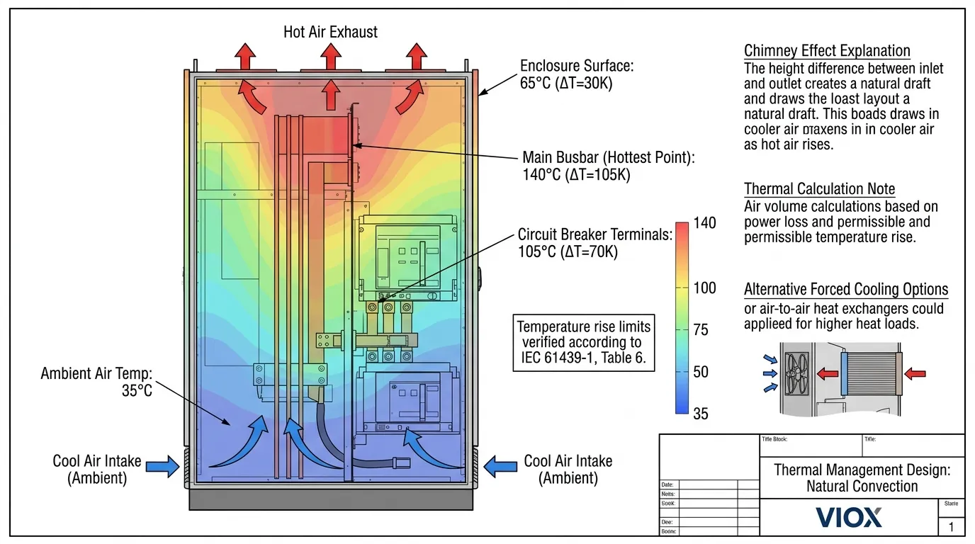
Η επαλήθευση της αύξησης της θερμοκρασίας είναι από τις πιο κρίσιμες πτυχές της συμμόρφωσης με το IEC 61439. Η υπερβολική θερμότητα υποβαθμίζει τη μόνωση, επιταχύνει τη γήρανση και δημιουργεί κινδύνους πυρκαγιάς. Το πρότυπο θεσπίζει συγκεκριμένα όρια αύξησης της θερμοκρασίας που δεν πρέπει να υπερβαίνονται υπό συνθήκες ονομαστικού ρεύματος.
IEC 61439-1 Πίνακας 6: Μέγιστα Όρια Αύξησης Θερμοκρασίας
| Στοιχείο | Όριο Αύξησης Θερμοκρασίας (K) | Σημειώσεις |
|---|---|---|
| Γυμνοί χάλκινοι ζυγοί | 105 | Υψηλότερα όρια για επιφάνειες με επικάλυψη αργύρου ή νικελίου |
| Ζυγοί με Επικασσιτερωμένους αρμούς | 90 | Περιορίζεται από την ακεραιότητα της συγκόλλησης |
| Ακροδέκτες για εξωτερικά μονωμένα καλώδια | 70 | Βασίζεται στην ονομαστική τιμή μόνωσης καλωδίου (PVC/PE) |
| Ακροδέκτες για εξωτερικά καλώδια XLPE | 90 | Υψηλότερη ικανότητα θερμοκρασίας της μόνωσης XLPE |
| Μέσα χειροκίνητης λειτουργίας (μέταλλο) | 25 | Επιφάνειες που είναι ασφαλείς για επαφή |
| Μέσα χειροκίνητης λειτουργίας (μονωτικά) | 35 | Χαμηλότερο όριο για μονωτικά υλικά |
| Εξωτερικές επιφάνειες περιβλήματος | 30 | Θεώρηση ασφάλειας για παρακείμενα υλικά |
Η επαλήθευση της αύξησης της θερμοκρασίας λαμβάνει υπόψη τον Ονομαστικός Συντελεστής Ποικιλομορφίας (RDF), ο οποίος αναγνωρίζει ότι δεν λειτουργούν όλα τα κυκλώματα με πλήρες φορτίο ταυτόχρονα. Οι τιμές RDF κυμαίνονται από 1,0 για τα κυκλώματα παροχής εισερχόμενης τροφοδοσίας έως 0,4 για πίνακες διανομής με πολλά εξερχόμενα κυκλώματα. Αυτός ο συντελεστής πολλαπλασιάζει το ονομαστικό ρεύμα για υπολογισμούς αύξησης της θερμοκρασίας, επιτρέποντας πιο ρεαλιστικούς και οικονομικούς σχεδιασμούς χωρίς συμβιβασμούς στην ασφάλεια.
Για τη θερμική διαχείριση, οι μηχανικοί πρέπει να λάβουν υπόψη:
- Φυσική μεταφορά μέσω ανοιγμάτων εξαερισμού τοποθετημένων για να αξιοποιήσουν το φαινόμενο καμινάδας
- Αναγκαστικός αερισμός για συγκροτήματα υψηλής πυκνότητας που υπερβαίνουν τα 6300A
- Απαγωγή θερμότητας από διακόπτες κυκλώματος και άλλα εξαρτήματα με βάση τα δεδομένα απώλειας ισχύος IEC 60947
- Υποβάθμιση της ονομαστικής τιμής της θερμοκρασίας περιβάλλοντος όταν οι εγκαταστάσεις υπερβαίνουν την τυπική αναφορά 35°C
Επαλήθευση Αντοχής σε Βραχυκύκλωμα
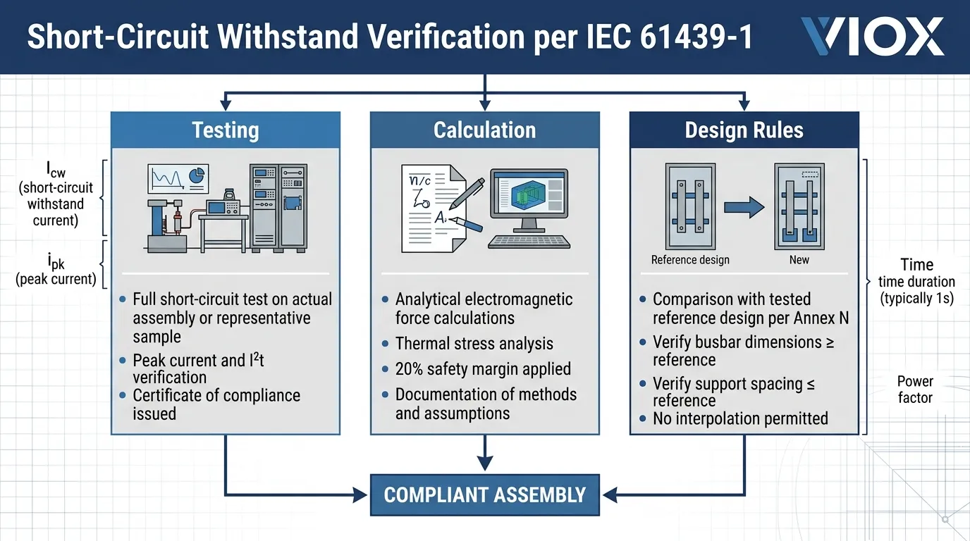
Το IEC 61439 επιβάλλει ότι όλα τα συγκροτήματα πρέπει να αντέχουν στις μηχανικές και θερμικές καταπονήσεις των ρευμάτων βραχυκυκλώματος. Η ονομαστική τιμή ρεύματος αντοχής σε βραχυκύκλωμα (Icw) του συγκροτήματος αντιπροσωπεύει το μέγιστο ρεύμα που μπορεί να μεταφέρει με ασφάλεια το συγκρότημα για μια καθορισμένη διάρκεια (συνήθως 1 δευτερόλεπτο) χωρίς ζημιά.
Επιλογές Επαλήθευσης:
- Δοκιμές — Πλήρης δοκιμή βραχυκυκλώματος στο πραγματικό συγκρότημα ή σε αντιπροσωπευτικό δείγμα
- Υπολογισμός — Αναλυτική επαλήθευση χρησιμοποιώντας αναγνωρισμένες μηχανικές μεθόδους με περιθώρια ασφαλείας
- Σύγκριση με Σχέδιο Αναφοράς — Σύγκριση με ένα δοκιμασμένο σχέδιο αναφοράς με ίσες ή μεγαλύτερες παραμέτρους
Η επαλήθευση βραχυκυκλώματος πρέπει να λαμβάνει υπόψη:
- Αντοχή σε ρεύμα κορυφής (σχετίζεται με το Icw μέσω του συντελεστή “n” συνήθως 1,5-2,1 ανάλογα με τον συντελεστή ισχύος)
- Θερμική καταπόνηση (I²t) μέσω των χαρακτηριστικών εκκαθάρισης της προστατευτικής συσκευής
- Ηλεκτρομαγνητικές δυνάμεις μεταξύ αγωγών, ιδιαίτερα για ράγες μεταφοράς χωρίς επαρκή στήριξη
- Συντονισμός με προστατευτικές συσκευές για να διασφαλιστεί ότι το συγκρότημα προστατεύεται υπό συνθήκες σφάλματος
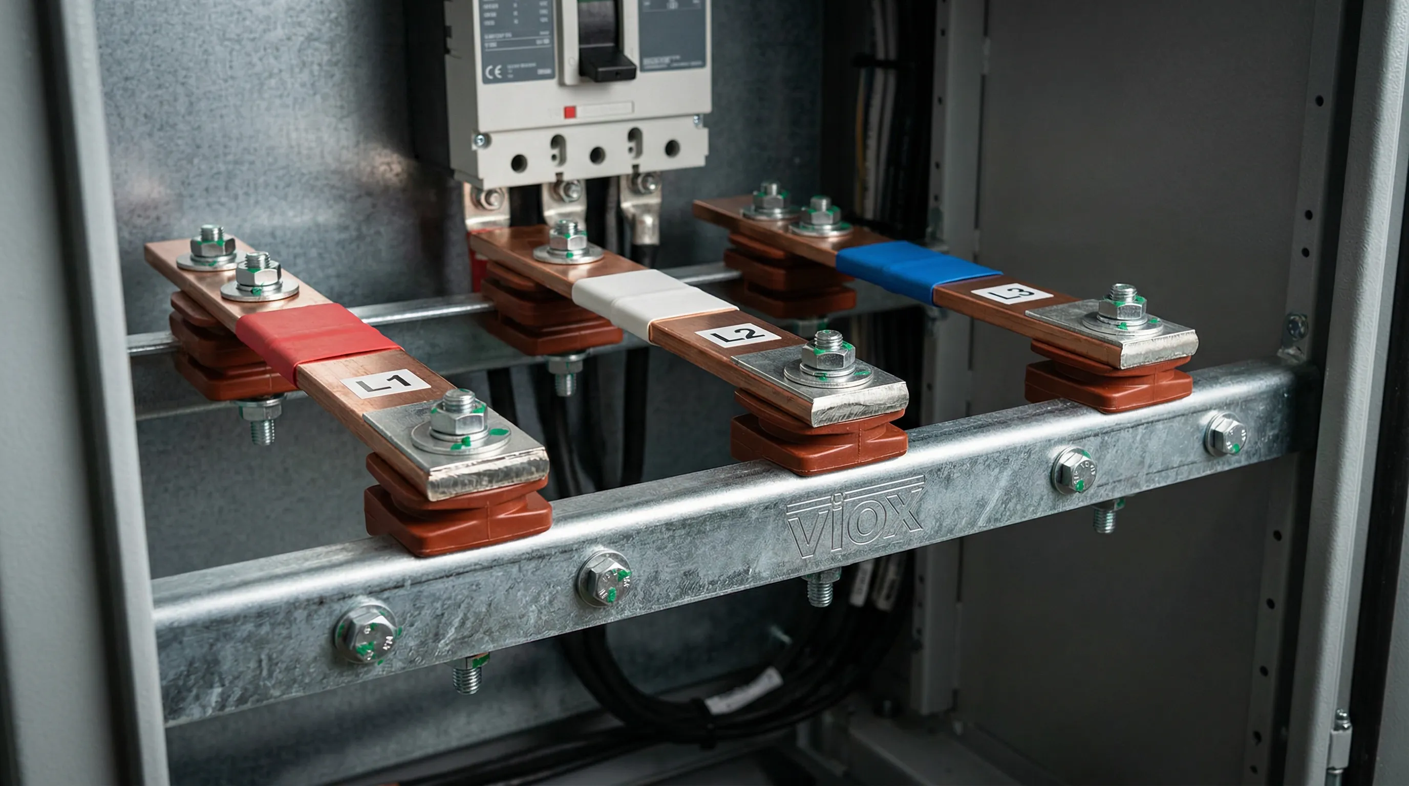
Για συστήματα χάλκινων ζυγών, οι απαιτήσεις απόστασης και στήριξης είναι κρίσιμες. Το IEC 61439 επιτρέπει την επαλήθευση κανόνων σχεδιασμού της αντοχής σε βραχυκύκλωμα των ζυγών μέσω υπολογισμού ή σύγκρισης με δοκιμασμένα σχέδια αναφοράς, υπό την προϋπόθεση ότι όλα τα κριτήρια, συμπεριλαμβανομένων των διαστάσεων του αγωγού, της απόστασης και των διατάξεων στήριξης, πληρούν ή υπερβαίνουν την αναφορά.
Διηλεκτρικές Ιδιότητες και Αποστάσεις
Ο συντονισμός μόνωσης διασφαλίζει ότι τα συγκροτήματα αντέχουν σε τάσεις λειτουργίας, προσωρινές υπερτάσεις και παροδικές υπερτάσεις. Το IEC 61439 καθορίζει:
Ελάχιστες Αποστάσεις στον Αέρα και Επιφανειακές Αποστάσεις Διαρροής:
| Ονομαστική Τάση Μόνωσης (V) | Ελάχιστη Απόσταση στον Αέρα (mm) | Ελάχιστη Επιφανειακή Απόσταση Διαρροής (mm) — Βαθμός Ρύπανσης 3 |
|---|---|---|
| ≤ 300 | 5.5 | 8.0 |
| 300-600 | 8.0 | 12.0 |
| 600-1000 | 14.0 | 20.0 |
Το πρότυπο απαιτεί από τα συγκροτήματα να αντέχουν:
- Δοκιμές τάσης αντοχής συχνότητας ισχύος (συνήθως 2kV AC για 1 δευτερόλεπτο για συστήματα 400V)
- Δοκιμές τάσης αντοχής κρουστικής (8kV για συστήματα 400V στην κατηγορία υπέρτασης III)
- Επαλήθευση ότι οι αποστάσεις διατηρούνται κατά τη διάρκεια της συναρμολόγησης και καθ' όλη τη διάρκεια ζωής
Οι σχεδιαστές πρέπει να λαμβάνουν υπόψη τη μείωση της ονομαστικής τιμής λόγω υψομέτρου — οι αποστάσεις πρέπει να αυξάνονται κατά περίπου 1% ανά 100m πάνω από τα 2000m. Αυτό είναι ιδιαίτερα σημαντικό για ηλεκτρικούς πίνακες που προορίζονται για εγκαταστάσεις σε μεγάλο υψόμετρο.
Μορφές Εσωτερικού Διαχωρισμού: Περιορισμός Σφάλματος Τόξου
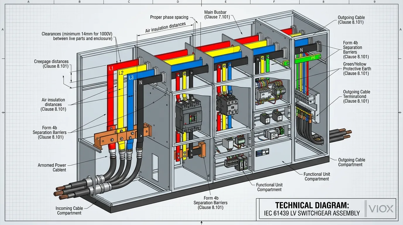
Το IEC 61439 ορίζει Μορφές Εσωτερικού Διαχωρισμού που καθορίζουν τον βαθμό διαχωρισμού μεταξύ ζυγών, λειτουργικών μονάδων και ακροδεκτών. Αυτές οι μορφές κυμαίνονται από τη Μορφή 1 (χωρίς διαχωρισμό) έως τη Μορφή 4b (διαχωρισμός ζυγών, λειτουργικών μονάδων και ακροδεκτών, συμπεριλαμβανομένων των διασυνδέσεων μεταξύ των μονάδων).
| Μορφή | Διαχωρισμός Ζυγών | Διαχωρισμός Λειτουργικής Μονάδας | Διαχωρισμός Ακροδεκτών | Εφαρμογή |
|---|---|---|---|---|
| Μορφή 1 | Κανένας | Κανένας | Κανένας | Απλή διανομή, ελάχιστες απαιτήσεις ασφάλειας |
| Μορφή 2α | Ναι | Κανένας | Κανένας | Βασική απομόνωση ζυγών |
| Μορφή 2β | Ναι | Κανένας | Ναι | Διαχωρισμός πρόσβασης ακροδεκτών |
| Μορφή 3α | Ναι | Ναι, χωρίς ακροδέκτες | Κανένας | Κέντρα ελέγχου κινητήρων με περιορισμένο διαχωρισμό |
| Μορφή 3β | Ναι | Ναι, χωρίς ακροδέκτες | Ναι | Τυπικός βιομηχανικός ηλεκτρικός πίνακας |
| Μορφή 4α | Ναι | Ναι, συμπεριλαμβανομένων των ακροδεκτών | Ναι (ίδιο διαμέρισμα) | Διαχωρισμός υψηλής ακεραιότητας |
| Μορφή 4β | Ναι | Ναι, συμπεριλαμβανομένων των ακροδεκτών | Ναι (ξεχωριστά διαμερίσματα) | Μέγιστη ασφάλεια, κρίσιμες εφαρμογές |
Οι υψηλότεροι αριθμοί μορφής παρέχουν μεγαλύτερο περιορισμό σφάλματος τόξου και προστασία προσωπικού, αλλά αυξάνουν το κόστος και την πολυπλοκότητα. Η μορφή 4b, για παράδειγμα, απαιτεί ξεχωριστά διαμερίσματα για τους ακροδέκτες κάθε λειτουργικής μονάδας, επηρεάζοντας σημαντικά το σχεδιασμό του περιβλήματος και την απαγωγή θερμότητας.
Η επιλογή της μορφής διαχωρισμού περιλαμβάνει την εξισορρόπηση:
- Απαιτήσεις ασφάλειας (πρόσβαση προσωπικού, περιορισμός σφάλματος τόξου)
- Ανάγκες συντήρησης (προσβασιμότητα για συντήρηση μεμονωμένων μονάδων)
- Θερμική διαχείριση (ο διαχωρισμός μπορεί να εμποδίσει τη ροή αέρα)
- Περιορισμοί κόστους (οι υψηλότερες μορφές απαιτούν περισσότερο υλικό και πολύπλοκη κατασκευή)
- Κρισιμότητα εφαρμογής (τα κέντρα δεδομένων, τα νοσοκομεία συνήθως καθορίζουν τη Μορφή 4)
Μέθοδοι Επαλήθευσης: Δοκιμές, Υπολογισμός και Κανόνες Σχεδιασμού
Το IEC 61439 παρέχει τρεις διαδρομές επαλήθευσης, αναγνωρίζοντας ότι η πλήρης δοκιμή κάθε παραλλαγής συγκροτήματος είναι ανέφικτη:
Επαλήθευση με Δοκιμές
Η παραδοσιακή προσέγγιση όπου το πραγματικό συγκρότημα υποβάλλεται σε εργαστηριακές δοκιμές. Απαιτείται για:
- Άνοδος θερμοκρασίας (εκτός εάν ισχύουν κανόνες σχεδιασμού)
- Αντοχή σε βραχυκύκλωμα (εκτός εάν ισχύουν υπολογισμοί ή κανόνες σχεδιασμού)
- Διηλεκτρικές ιδιότητες
- Μηχανική λειτουργία
- Βαθμός προστασίας (επαλήθευση βαθμού IP)
Επαλήθευση με Υπολογισμό
Επιτρέπονται αναλυτικές μέθοδοι για ορισμένα χαρακτηριστικά:
- Άνοδος θερμοκρασίας χρησιμοποιώντας θερμική μοντελοποίηση με επικυρωμένα δεδομένα
- Αντοχή σε βραχυκύκλωμα χρησιμοποιώντας υπολογισμούς ηλεκτρομαγνητικής δύναμης
- Επαλήθευση ερπυσμού και αποστάσεων μέσω ανάλυσης διαστάσεων
Οι υπολογισμοί πρέπει να χρησιμοποιούν αναγνωρισμένες μηχανικές μεθόδους με κατάλληλα περιθώρια ασφαλείας. Το πρότυπο απαιτεί συντηρητικές παραδοχές — οι ονομαστικές τιμές της συσκευής πρέπει να μειώνονται κατά 20% όταν χρησιμοποιούνται σε υπολογισμούς, εκτός εάν υπάρχουν διαθέσιμα συγκεκριμένα δεδομένα εξαρτημάτων.
Επαλήθευση με Κανόνες Σχεδιασμού
Σύγκριση με δοκιμασμένα σχέδια αναφοράς:
- Επιτρέπεται για αντοχή σε βραχυκύκλωμα όταν οι διατομές, τα υλικά και η απόσταση των στηρίξεων των ράβδων πληρούν ή υπερβαίνουν την αναφορά
- Το Παράρτημα N του IEC 61439-1 παρέχει συγκεκριμένες παραμέτρους κανόνων σχεδιασμού για συστήματα ράβδων
- Το σχέδιο αναφοράς πρέπει να έχει δοκιμαστεί στα ίδια ή υψηλότερα επίπεδα καταπόνησης
- Όλες οι παράμετροι πρέπει να είναι ίσες ή ανώτερες από την αναφορά — δεν επιτρέπεται παρεμβολή
Αυτή η προσέγγιση είναι ιδιαίτερα πολύτιμη για συστήματα διανομής ράβδων και τυποποιημένες σειρές διακοπτών όπου πολλαπλές διαμορφώσεις μοιράζονται κοινές αρχές κατασκευής.
Πλαίσιο Ευθύνης: Αρχικός Κατασκευαστής έναντι Κατασκευαστή Συναρμολόγησης
Το IEC 61439 διαχωρίζει σαφώς τις ευθύνες μεταξύ δύο βασικών οντοτήτων:
Αρχικός Κατασκευαστής (Κατασκευαστής Συστήματος):
- Σχεδιάζει το σύστημα συναρμολόγησης διακοπτών
- Καθιερώνει κανόνες σχεδιασμού και μεθόδους επαλήθευσης
- Παρέχει δοκιμασμένα σχέδια αναφοράς
- Καθορίζει εξαρτήματα, υλικά και μεθόδους κατασκευής
- Εκδίδει τεκμηρίωση συστήματος και οδηγίες συμμόρφωσης
Κατασκευαστής Συναρμολόγησης (Κατασκευαστής Πινάκων):
- Κατασκευάζει την τελική συναρμολόγηση διακοπτών
- Επαληθεύει τη συμμόρφωση με το πρότυπο χρησιμοποιώντας μεθόδους που παρέχονται από τον Αρχικό Κατασκευαστή
- Εκτελεί συνήθη επαλήθευση (συνήθεις δοκιμές σε κάθε συναρμολόγηση)
- Αναλαμβάνει την ευθύνη για την ολοκληρωμένη συναρμολόγηση που διατίθεται στην αγορά
- Τηρεί τεχνική τεκμηρίωση και Δήλωση Συμμόρφωσης
Αυτό το πλαίσιο διασφαλίζει ότι ενώ η τεχνογνωσία σχεδιασμού συστήματος ανήκει στον Αρχικό Κατασκευαστή, η λογοδοσία για το τελικό προϊόν ανήκει στον Κατασκευαστή Συναρμολόγησης. Για τους επαγγελματίες προμηθειών, η κατανόηση αυτής της διάκρισης είναι απαραίτητη κατά την αξιολόγηση των ισχυρισμών συμμόρφωσης των προμηθευτών.
Πρακτική Εφαρμογή: Λίστα Ελέγχου Σχεδιασμού για Μηχανικούς
Φάση Προ-Σχεδιασμού
- Καθορίστε τις απαιτήσεις εφαρμογής — Τάση, ρεύμα, επίπεδο σφάλματος, περιβαλλοντικές συνθήκες
- Επιλέξτε το κατάλληλο μέρος του IEC 61439 — -2 για διακόπτες ισχύος, -3 για πίνακες διανομής, -6 για διανομή ράβδων
- Καθορίστε τον Ονομαστικό Συντελεστή Διαφορετικότητας — Βασίζεται στα χαρακτηριστικά φορτίου και στον αριθμό κυκλωμάτων
- Καθιερώστε την απαιτούμενη Μορφή Διαχωρισμού — Βασίζεται στις απαιτήσεις ασφαλείας και στην κρισιμότητα της εφαρμογής
- Προσδιορίστε τους ισχύοντες συντελεστές μείωσης — Θερμοκρασία, υψόμετρο, αρμονικές, συνθήκες εγκατάστασης
Φάση Σχεδιασμού
- Υπολογίστε τη διαστασιολόγηση των ράβδων — Βασίζεται στο ονομαστικό ρεύμα, το RDF, τα όρια αύξησης της θερμοκρασίας και το υλικό των ράβδων
- Επαληθεύστε την αντοχή σε βραχυκύκλωμα — Δοκιμή, υπολογισμός ή σύγκριση με σχέδιο αναφοράς
- Καθορίστε τις αποστάσεις και τον ερπυσμό — Βασίζεται στην ονομαστική τάση μόνωσης και στον βαθμό ρύπανσης
- Σχεδιάστε τη θερμική διαχείριση — Φυσικός αερισμός, εξαναγκασμένος αερισμός ή κλιματισμός
- Επιλέξτε την ονομαστική προστασία περιβλήματος — Βαθμός IP με βάση το περιβάλλον, βαθμός IK για μηχανική κρούση
- Σχεδιάστε τον εσωτερικό διαχωρισμό — Μορφή 1 έως 4b με βάση τις απαιτήσεις ασφαλείας
Φάση Επαλήθευσης
- Διεξάγετε επαλήθευση σχεδιασμού — Δοκιμές, υπολογισμός ή κανόνες σχεδιασμού, ανάλογα με την περίπτωση
- Εκτελέστε δοκιμές ρουτίνας — Διηλεκτρική αντοχή, καλωδίωση, συνέχεια και μηχανική λειτουργία σε κάθε συγκρότημα
- Συντάξτε τεχνική τεκμηρίωση — Σχέδια, προδιαγραφές, εκθέσεις δοκιμών, εκτίμηση κινδύνου
- Εκδώστε Δήλωση Συμμόρφωσης — Τεκμηρίωση σήμανσης CE για πρόσβαση στην αγορά της ΕΕ
Κοινές Σχεδιαστικές Παγίδες και Πώς να τις Αποφύγετε
Παγίδα 1: Αγνοώντας τον Ονομαστικό Συντελεστή Διαφοροποίησης (Rated Diversity Factor - RDF)
Τεύχος: Ο σχεδιασμός όλων των ζυγών για ταυτόχρονη λειτουργία πλήρους φορτίου οδηγεί σε υπερμεγέθη, ακριβά συστήματα.
Λύση: Εφαρμόστε κατάλληλες τιμές RDF—0,9-1,0 για κυκλώματα εισόδου, 0,8 για διανομή ισχύος, 0,6-0,7 για πίνακες διανομής με πολλά κυκλώματα.
Παγίδα 2: Ανεπαρκής Θερμική Διαχείριση
Τεύχος: Εμπιστοσύνη σε θεωρητικούς υπολογισμούς χωρίς να λαμβάνονται υπόψη οι συνθήκες εγκατάστασης (κλειστοί χώροι, ηλιακό κέρδος, παρακείμενες πηγές θερμότητας).
Λύση: Εκτελέστε θερμική μοντελοποίηση με ρεαλιστικές οριακές συνθήκες. καθορίστε εξαναγκασμένο αερισμό για συγκροτήματα υψηλής πυκνότητας. αφήστε επαρκή απόσταση γύρω από τα περιβλήματα.
Παγίδα 3: Αναντιστοιχία Ονομαστικής Ικανότητας Βραχυκύκλωσης
Τεύχος: Η ονομαστική τιμή Icw του συγκροτήματος υπερβαίνει την ικανότητα διακοπής της προστατευτικής συσκευής ή ανεπαρκής στήριξη για ηλεκτροδυναμικές δυνάμεις.
Λύση: Διασφαλίστε ότι διακόπτης κυκλώματος η ικανότητα διακοπής ισούται ή υπερβαίνει την ονομαστική αντοχή του συγκροτήματος. επαληθεύστε ότι η απόσταση στήριξης των ζυγών πληροί τις απαιτήσεις των κανόνων σχεδιασμού.
Παγίδα 4: Παραμέληση της Επαλήθευσης των Αποστάσεων Ασφαλείας
Τεύχος: Υποθέτοντας τυπικές αποστάσεις ασφαλείας χωρίς να λαμβάνονται υπόψη οι ανοχές εγκατάστασης, η διόγκωση του υλικού ή η κίνηση του αγωγού υπό συνθήκες σφάλματος.
Λύση: Σχεδιάστε με περιθώριο—καθορίστε αποστάσεις ασφαλείας 20% μεγαλύτερες από τις ελάχιστες απαιτήσεις. επαληθεύστε με φυσική επιθεώρηση κατά τη διάρκεια της συναρμολόγησης του πρωτοτύπου.
Παγίδα 5: Ασυμβατότητα Μορφής Διαχωρισμού
Τεύχος: Καθορισμός υψηλών μορφών διαχωρισμού (Μορφή 4) χωρίς να λαμβάνεται υπόψη ο θερμικός αντίκτυπος της διαμερισματοποίησης.
Λύση: Αξιολογήστε τις απαιτήσεις θερμικής διαχείρισης νωρίς. καθορίστε αερισμό ή ψύξη για συγκροτήματα Μορφής 3 και 4. εξετάστε εξαερισμός του ηλεκτρικού πίνακα στρατηγικές.
Σύντομη ενότητα FAQ
Ε: Ποια είναι η διαφορά μεταξύ του προτύπου IEC 61439 και του παλαιού προτύπου IEC 60439;
Α: Το πρότυπο IEC 61439 αντικατέστησε το πρότυπο IEC 60439 το 2009 και καταργεί τη διάκριση μεταξύ των Συγκροτημάτων που έχουν Υποβληθεί σε Δοκιμές Τύπου (Type-Tested Assemblies - TTA) και των Συγκροτημάτων που έχουν Υποβληθεί Μερικώς σε Δοκιμές Τύπου (Partially Type-Tested Assemblies - PTTA). Σύμφωνα με το πρότυπο IEC 61439, όλα τα συγκροτήματα πρέπει να πληρούν τις ίδιες απαιτήσεις ασφαλείας ανεξάρτητα από τη μέθοδο επαλήθευσης (δοκιμή, υπολογισμός ή κανόνες σχεδιασμού). Το νέο πρότυπο εισάγει επίσης σαφέστερο διαχωρισμό ευθυνών μεταξύ των Αρχικών Κατασκευαστών και των Κατασκευαστών Συγκροτημάτων και καθιερώνει την έννοια του Ονομαστικού Συντελεστή Διαφοροποίησης (Rated Diversity Factor - RDF) για ρεαλιστικούς υπολογισμούς φορτίου.
Ε: Μπορώ να χρησιμοποιήσω το πρότυπο IEC 61439 για το σχεδιασμό ηλεκτρικού εξοπλισμού διανομής DC;
Α: Ναι, το πρότυπο IEC 61439-1:2020 περιλαμβάνει ρητά απαιτήσεις για εφαρμογές DC έως 1500V DC. Ωστόσο, το DC εισάγει μοναδικές προκλήσεις, συμπεριλαμβανομένου του συνεχούς τόξου κατά τη διάρκεια σφαλμάτων (χωρίς φυσική διέλευση μηδενικού ρεύματος), υψηλότερη αύξηση της θερμοκρασίας λόγω έλλειψης ανακατανομής του φαινομένου επιδερμίδας και διαφορετικές απαιτήσεις απόστασης ερπυσμού. Για εφαρμογές DC, δώστε ιδιαίτερη προσοχή στην Αυτόματος διακόπτης DC επιλογή, το σχεδιασμό του θαλάμου τόξου και τις εκτιμήσεις πολικότητας.
Ε: Πώς μπορώ να καθορίσω τον σωστό Ονομαστικό Συντελεστή Διαφοροποίησης (Rated Diversity Factor - RDF) για το συγκρότημα ηλεκτρικού εξοπλισμού διανομής;
Α: Το RDF εξαρτάται από τον αριθμό των εξερχόμενων κυκλωμάτων και τον τύπο εφαρμογής. Το πρότυπο IEC 61439-1 παρέχει τιμές αναφοράς: 1,0 για κυκλώματα παροχής εισόδου. 0,9 για 2-3 εξερχόμενα κυκλώματα. 0,8 για 4-5 κυκλώματα. 0,7 για 6-9 κυκλώματα. και 0,6 για 10+ κυκλώματα. Οι πίνακες διανομής (Distribution Boards - DBOs) σύμφωνα με το πρότυπο IEC 61439-3 χρησιμοποιούν διαφορετικά κριτήρια βάσει της διαφοροποίησης του συνδεδεμένου φορτίου. Να τεκμηριώνετε πάντα τη βάση για την επιλογή του RDF στο τεχνικό αρχείο.
Ε: Απαιτείται πιστοποίηση από τρίτους για τη συμμόρφωση με το πρότυπο IEC 61439;
Α: Όχι, το πρότυπο IEC 61439 δεν επιβάλλει πιστοποίηση από τρίτους. Το πρότυπο λειτουργεί με αυτο-πιστοποίηση από τον Κατασκευαστή Συγκροτημάτων, ο οποίος αναλαμβάνει την ευθύνη για τη συμμόρφωση. Ωστόσο, πολλές προδιαγραφές (ιδιαίτερα στον τομέα του πετρελαίου και του φυσικού αερίου, των κέντρων δεδομένων και των κρίσιμων υποδομών) απαιτούν επαλήθευση από τρίτους μέσω φορέων όπως η UL, η IECEx ή κοινοποιημένοι φορείς για τη σήμανση CE. Αν και δεν είναι υποχρεωτική, η πιστοποίηση από τρίτους παρέχει ανεξάρτητη επικύρωση των ισχυρισμών συμμόρφωσης.
Ε: Ποιες δοκιμές ρουτίνας πρέπει να εκτελούνται σε κάθε συγκρότημα IEC 61439;
Α: Κάθε συγκρότημα πρέπει να υποβάλλεται σε δοκιμές ρουτίνας πριν από την αποστολή: δοκιμή μόνωσης (διηλεκτρική αντοχή σε 1kV AC ή 1,5kV DC για 1 δευτερόλεπτο). συνέχεια των προστατευτικών κυκλωμάτων (μέγιστο 0,05Ω μεταξύ περιβλήματος και ακροδέκτη γείωσης). επιθεώρηση της καλωδίωσης και της εγκατάστασης των εξαρτημάτων. και επαλήθευση της μηχανικής λειτουργίας (διακόπτες, διακόπτες κυκλώματος, αλληλοασφαλίσεις). Τα αποτελέσματα των δοκιμών πρέπει να καταγράφονται και να φυλάσσονται στο τεχνικό αρχείο.
Ε: Πώς αντιμετωπίζει το πρότυπο IEC 61439 τους κινδύνους από λάμψη τόξου;
Α: Ενώ το πρότυπο IEC 61439 δεν επιβάλλει συγκεκριμένα δοκιμές περιορισμού σφάλματος τόξου (ανατρέξτε στο πρότυπο IEC TR 61641 για αυτό), οι Μορφές Εσωτερικού Διαχωρισμού (Μορφή 2b έως 4b) παρέχουν βαθμούς περιορισμού σφάλματος τόξου. Η Μορφή 4b προσφέρει την υψηλότερη προστασία με πλήρη διαμερισματοποίηση. Για εφαρμογές που απαιτούν επαληθευμένο περιορισμό σφάλματος τόξου (όπως στον τομέα του πετρελαίου και του φυσικού αερίου), καθορίστε τη συμμόρφωση τόσο με το πρότυπο IEC 61439 όσο και με το πρότυπο IEC TR 61641, το οποίο παρέχει μεθόδους δοκιμής για την εσωτερική ταξινόμηση τόξου (Internal Arc Classification - IAC).
Συμπέρασμα: Μηχανική Αριστεία Μέσω της Συμμόρφωσης με τα Πρότυπα
Το πρότυπο IEC 61439 αντιπροσωπεύει ένα ώριμο, ολοκληρωμένο πλαίσιο για το σχεδιασμό ηλεκτρικού εξοπλισμού διανομής χαμηλής τάσης που εξισορροπεί την αυστηρότητα της ασφάλειας με την πρακτικότητα της μηχανικής. Παρέχοντας πολλαπλές διαδρομές επαλήθευσης—δοκιμές, υπολογισμούς και κανόνες σχεδιασμού—το πρότυπο καλύπτει τις διαφορετικές ανάγκες των κατασκευαστών προσαρμοσμένων πινάκων και των μαζικών κατασκευαστών, διατηρώντας παράλληλα συνεπή σημεία αναφοράς ασφάλειας.
Για τους ηλεκτρολόγους μηχανικούς και τους επαγγελματίες προμηθειών, η κατανόηση του προτύπου IEC 61439 δεν αφορά απλώς την επιλογή ενός πλαισίου συμμόρφωσης. Οι απαιτήσεις του προτύπου για τη διαχείριση της θερμοκρασίας, την αντοχή σε βραχυκύκλωμα και τον εσωτερικό διαχωρισμό επηρεάζουν άμεσα την αξιοπιστία του εξοπλισμού, τη διάρκεια ζωής και την ασφάλεια του προσωπικού. Η σωστή εφαρμογή του Ονομαστικού Συντελεστή Διαφοροποίησης μπορεί να αποφέρει σημαντική εξοικονόμηση κόστους χωρίς να διακυβεύεται η απόδοση, ενώ η σωστή προδιαγραφή των Μορφών Διαχωρισμού εξασφαλίζει την κατάλληλη προστασία για το περιβάλλον εφαρμογής.
Καθώς τα συγκροτήματα ηλεκτρικού εξοπλισμού διανομής γίνονται ολοένα και πιο εξελιγμένα—ενσωματώνοντας έξυπνη παρακολούθηση, προστασία από υπερτάσεις, και διεπαφές ανανεώσιμων πηγών ενέργειας—οι θεμελιώδεις απαιτήσεις του προτύπου IEC 61439 παραμένουν ουσιαστικές. Το πλαίσιο επαλήθευσης σχεδιασμού, η οριοθέτηση ευθυνών και τα σημεία αναφοράς απόδοσης του προτύπου παρέχουν τη τεχνική βάση πάνω στην οποία χτίζονται τα σύγχρονα συστήματα ηλεκτρικής διανομής.
Για τους κατασκευαστές B2B όπως η VIOX Electric, η συμμόρφωση με το πρότυπο IEC 61439 είναι τόσο μια απαίτηση πρόσβασης στην αγορά όσο και ένα ανταγωνιστικό πλεονέκτημα. Τα συγκροτήματα που έχουν σχεδιαστεί και επαληθευτεί σύμφωνα με αυτό το πρότυπο αποδεικνύουν μηχανική αυστηρότητα, δέσμευση για την ασφάλεια και ετοιμότητα για την παγκόσμια αγορά—ιδιότητες που οι επαγγελματίες προμηθειών δίνουν προτεραιότητα κατά την επιλογή συνεργατών για έργα κρίσιμων υποδομών.
Τεχνική Αναφορά: Αυτός ο οδηγός βασίζεται στο πρότυπο IEC 61439-1:2020 “Συγκροτήματα ηλεκτρικού εξοπλισμού διανομής και ελέγχου χαμηλής τάσης — Μέρος 1: Γενικοί κανόνες” και στα σχετικά μέρη που αφορούν συγκεκριμένα προϊόντα. Για πλήρεις απαιτήσεις συμμόρφωσης, να συμβουλεύεστε πάντα το πλήρες κείμενο του προτύπου και τις ισχύουσες εθνικές παρεκκλίσεις. Ως κατασκευαστής εξοπλισμού ηλεκτρικής προστασίας B2B, η VIOX Electric παρέχει εξαρτήματα συμβατά με το πρότυπο IEC 61439 και τεχνική υποστήριξη για κατασκευαστές συγκροτημάτων ηλεκτρικού εξοπλισμού διανομής σε όλο τον κόσμο.
