 έναντι Μετασχηματιστών Τάσης (PTs): Ποια είναι η Διαφορά;")
Εισαγωγή: Ο Κρίσιμος Ρόλος των Μετασχηματιστών Οργάνων
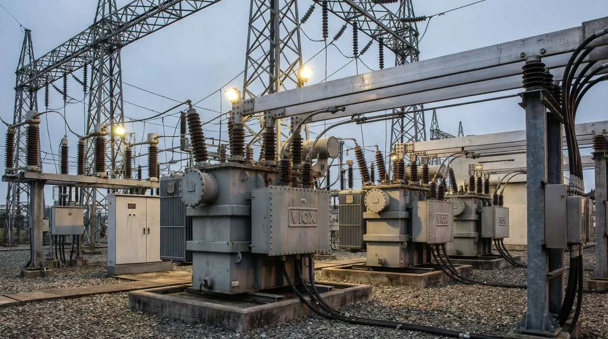
Στην πολύπλοκη αρχιτεκτονική των σύγχρονων ηλεκτρικών συστημάτων ισχύος, οι μετασχηματιστές οργάνων χρησιμεύουν ως τα ουσιώδη μάτια και αυτιά που καθιστούν τα δίκτυα υψηλής τάσης και υψηλού ρεύματος μετρήσιμα, ελέγξιμα και ασφαλή. Αυτές οι εξειδικευμένες συσκευές—συγκεκριμένα μετασχηματιστές ρεύματος (CTs) και μετασχηματιστές τάσης (PTs, επίσης γνωστοί ως μετασχηματιστές δυναμικού ή VTs)—εκτελούν μια κρίσιμη λειτουργία κλιμάκωσης. Μετατρέπουν τις ποσότητες του πρωτεύοντος συστήματος (χιλιάδες αμπέρ, εκατοντάδες κιλοβόλτ) σε τυποποιημένες, χαμηλού επιπέδου δευτερεύουσες τιμές (συνήθως 5 A και 115–120 V) που μπορούν να χειριστούν με ασφάλεια μετρητές, ρελέ και εξοπλισμός παρακολούθησης.
Για τους μηχανικούς, τους ολοκληρωτές συστημάτων και τους ειδικούς προμηθειών, η κατανόηση των θεμελιωδών διαφορών μεταξύ των CTs και των PTs δεν είναι απλώς ακαδημαϊκή—επηρεάζει άμεσα την ακρίβεια του συστήματος, την αξιοπιστία της προστασίας, την ασφάλεια του προσωπικού και τη συμμόρφωση με τους κανονισμούς. Η εσφαλμένη εφαρμογή μπορεί να οδηγήσει σε σφάλματα μέτρησης, αστοχίες προστασίας ή ακόμη και σε επικίνδυνες συνθήκες, όπως βλάβη μόνωσης ή έκρηξη μετασχηματιστή.
Αυτός ο περιεκτικός οδηγός από την VIOX Electric, έναν κορυφαίο κατασκευαστή ηλεκτρικού εξοπλισμού, διευκρινίζει τους διακριτούς ρόλους, τα σχέδια, τα πρότυπα και τις εφαρμογές των μετασχηματιστών ρεύματος έναντι των μετασχηματιστών τάσης. Είτε καθορίζετε μετασχηματιστές για έναν νέο υποσταθμό, είτε εκσυγχρονίζετε μια υπάρχουσα εγκατάσταση, είτε απλώς επιδιώκετε να εμβαθύνετε τις τεχνικές σας γνώσεις, αυτό το άρθρο παρέχει τη σαφή σύγκριση που χρειάζεστε για να λάβετε τεκμηριωμένες αποφάσεις.
Τι είναι οι Μετασχηματιστές Ρεύματος (CTs);
Ένας μετασχηματιστής ρεύματος είναι ένας τύπος μετασχηματιστή οργάνου που έχει σχεδιαστεί για να μειώνει τα υψηλά πρωτεύοντα ρεύματα σε ένα τυποποιημένο, χαμηλού επιπέδου δευτερεύον ρεύμα—συνήθως 5 A ή 1 A—για ασφαλή μέτρηση και προστασία. Σε αντίθεση με τους μετασχηματιστές ισχύος που μεταφέρουν ενέργεια, οι CTs είναι συσκευές ανίχνευσης που παρέχουν μια ακριβή αναλογική αναπαράσταση του πρωτεύοντος ρεύματος, ενώ παράλληλα απομονώνουν ηλεκτρικά τα όργανα μέτρησης από το κύκλωμα υψηλής τάσης.
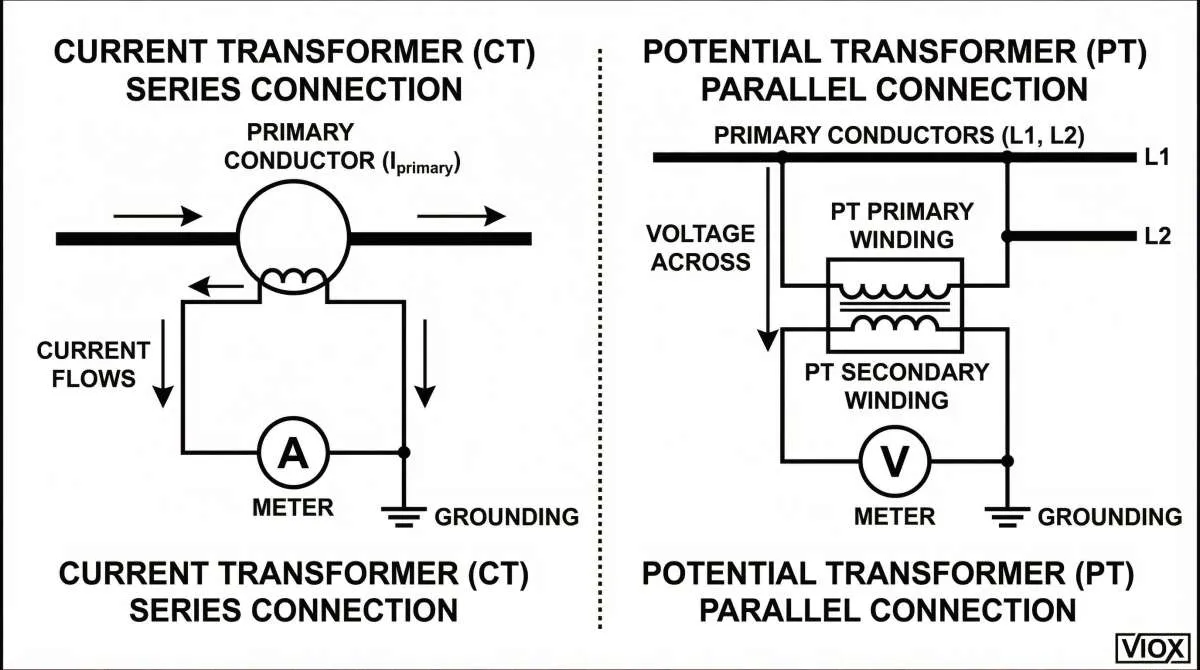
Βασική Αρχή Λειτουργίας: Οι CTs λειτουργούν με την ίδια αρχή ηλεκτρομαγνητικής επαγωγής με τους συμβατικούς μετασχηματιστές, αλλά με μια κρίσιμη σχεδιαστική διάκριση: το πρωτεύον τύλιγμα αποτελείται από πολύ λίγες σπείρες (συχνά μόνο έναν αγωγό ή ζυγό) και συνδέεται σε σειρά σειρά με τη γραμμή που μεταφέρει το ρεύμα που πρόκειται να μετρηθεί. Το δευτερεύον τύλιγμα έχει πολλές σπείρες από λεπτό σύρμα. Σύμφωνα με την αναλογία μετασχηματιστή $I_p \times N_p = I_s \times N_s$, το υψηλό πρωτεύον ρεύμα $I_p$ μετατρέπεται σε ένα πολύ χαμηλότερο δευτερεύον ρεύμα $I_s$ που μπορεί να χειριστεί με ασφάλεια από αμπερόμετρα, μετρητές ενέργειας, ρελέ προστασίας και συστήματα συλλογής δεδομένων.
Τυποποίηση και Ασφάλεια: Η δευτερεύουσα ονομαστική τιμή είναι διεθνώς τυποποιημένη στα 5 A (ή 1 A σε ορισμένες εφαρμογές), διασφαλίζοντας τη συμβατότητα μεταξύ συσκευών από διαφορετικούς κατασκευαστές. Ένας θεμελιώδης κανόνας ασφαλείας διέπει την εγκατάσταση των CTs: το δευτερεύον κύκλωμα δεν πρέπει ποτέ να είναι ανοιχτό όταν το πρωτεύον είναι ενεργοποιημένο. Ένα ανοιχτό δευτερεύον μπορεί να προκαλέσει τον κορεσμό του πυρήνα, προκαλώντας επικίνδυνα υψηλές τάσεις που θέτουν σε κίνδυνο την αστοχία της μόνωσης, τη δημιουργία τόξου ή ακόμη και την έκρηξη του μετασχηματιστή. Τα αχρησιμοποίητα δευτερεύοντα των CTs πρέπει να βραχυκυκλώνονται ή να συνδέονται σε ένα φορτίο.
- Μέτρηση ενέργειας (τιμολόγηση κοινής ωφέλειας, υπομέτρηση)
- Παρακολούθηση συστήματος (καταγραφή φορτίου, ανάλυση ποιότητας ισχύος)
- Ρελέ προστασίας (υπερένταση, διαφορική προστασία, προστασία απόστασης)
- Έλεγχος και αυτοματισμός (αλληλοσύνδεση βάσει ρεύματος, προστασία κινητήρα)
Στην VIOX Electric, κατασκευάζουμε CTs που πληρούν τα αυστηρά πρότυπα IEC και ANSI, διασφαλίζοντας ακρίβεια, αξιοπιστία και ασφάλεια για τις πιο απαιτητικές εφαρμογές σας.
Τι είναι οι Μετασχηματιστές Τάσης (PTs);
Ένας μετασχηματιστής τάσης, επίσης γνωστός ως μετασχηματιστής δυναμικού (VT), είναι ένας μετασχηματιστής οργάνου που μειώνει τις υψηλές τάσεις του συστήματος σε μια τυποποιημένη χαμηλή τάση—συνήθως 115 V ή 120 V—για ασφαλή μέτρηση και προστασία. Οι PTs παρέχουν ακριβή αναλογία τάσης και γαλβανική απομόνωση, επιτρέποντας στους μετρητές, τα ρελέ και τις συσκευές ελέγχου να λειτουργούν με ασφάλεια σε χαμηλά επίπεδα τάσης, ενώ παρακολουθούν κυκλώματα υψηλής τάσης.
Βασική Αρχή Λειτουργίας: Οι PTs είναι ουσιαστικά μετασχηματιστές υποβιβασμού ακριβείας. Το πρωτεύον τύλιγμα, το οποίο έχει πολλές σπείρες από λεπτό σύρμα, συνδέεται σε παράλληλο παράλληλη σύνδεση (shunt) κατά μήκος των δύο γραμμών ή μεταξύ γραμμής και γείωσης, η τάση των οποίων πρόκειται να μετρηθεί. Το δευτερεύον τύλιγμα έχει λιγότερες σπείρες, παράγοντας μια μειωμένη τάση εξόδου που διατηρεί μια σταθερή αναλογία με την πρωτεύουσα τάση. Ο μετασχηματισμός ακολουθεί τη σχέση $V_p / V_s = N_p / N_s$, όπου $V_p$ είναι η πρωτεύουσα τάση, $V_s$ είναι η δευτερεύουσα τάση και $N_p$, $N_s$ είναι οι αντίστοιχες σπείρες του τυλίγματος.
Τυποποίηση και Ασφάλεια: Οι δευτερεύουσες τάσεις είναι τυποποιημένες στα 115 V ή 120 V για μετρήσεις γραμμής προς γραμμή και 69,3 V ή 66,5 V για διαμορφώσεις γραμμής προς ουδέτερο, διασφαλίζοντας τη διαλειτουργικότητα σε παγκόσμιες εγκαταστάσεις. Σε αντίθεση με τους CTs, οι PTs μπορούν να λειτουργήσουν με ασφάλεια με ένα ανοιχτό δευτερεύον κύκλωμα. Ο κύριος κίνδυνος είναι βραχυκύκλωμα του δευτερεύοντος, το οποίο μπορεί να προκαλέσει υπερβολική ροή ρεύματος και θερμική βλάβη στα τυλίγματα. Οι PTs έχουν σχεδιαστεί για να αντέχουν συνεχείς συνθήκες υπέρτασης (συνήθως 110% της ονομαστικής τάσης) και υπερτάσεις έκτακτης ανάγκης μικρής διάρκειας, όπως ορίζονται από τις ομάδες IEEE.
- Μέτρηση τάσης (μέτρηση, παρακολούθηση συστήματος)
- Συγχρονισμός (παράλληλη σύνδεση γεννήτριας, διασύνδεση δικτύου)
- Ρελέ προστασίας (υποτάση, υπέρταση, προστασία απόστασης)
- Ανάλυση ποιότητας ισχύος (βύθιση τάσης, διόγκωση, παρακολούθηση αρμονικών)
Η VIOX Electric προμηθεύει PTs που συμμορφώνονται με τα διεθνή πρότυπα IEC και ANSI/IEEE, παρέχοντας την ακρίβεια και την ανθεκτικότητα που απαιτούνται για εφαρμογές κοινής ωφέλειας, βιομηχανικές και εμπορικές εφαρμογές.
CT έναντι PT: Βασικές Διαφορές με μια Ματιά
Ο ακόλουθος πίνακας συνοψίζει τις θεμελιώδεις διαφορές μεταξύ των μετασχηματιστών ρεύματος και των μετασχηματιστών τάσης σε πολλές διαστάσεις.
| Χαρακτηριστικό γνώρισμα | Μετασχηματιστής Ρεύματος (CT) | Μετασχηματιστής Τάσης (PT) / Μετασχηματιστής Δυναμικού (VT) |
|---|---|---|
| Κύρια λειτουργία | Υποβιβάζει υψηλό τρέχουσα σε ένα τυποποιημένο χαμηλό ρεύμα (συνήθως 5 A ή 1 A) για μέτρηση και προστασία. | Υποβιβάζει υψηλό τάση σε μια τυποποιημένη χαμηλή τάση (συνήθως 115 V ή 120 V) για μέτρηση και προστασία. |
| Σύνδεση Κυκλώματος | Συνδέεται σε σειρά σειρά με τον αγωγό που μεταφέρει το ρεύμα που πρόκειται να μετρηθεί. | Συνδέεται σε παράλληλο παράλληλη σύνδεση (shunt) κατά μήκος των γραμμών των οποίων η τάση πρόκειται να μετρηθεί. |
| Τύπος Μετασχηματιστή | Λειτουργεί ως μετασχηματιστής ανύψωσης τάσης (ανυψώνει την τάση για να υποβιβάσει το ρεύμα). | Λειτουργεί ως μετασχηματιστής υποβιβασμού τάσης (υποβιβάζει την τάση). |
| Πρωτεύον Τύλιγμα | Λίγες σπείρες (συχνά ένας μόνο αγωγός ή ζυγός). παχύς αγωγός για να χειριστεί υψηλό ρεύμα. | Πολλές σπείρες από λεπτό σύρμα για να αντέξουν την υψηλή τάση. |
| Δευτερεύον Τύλιγμα | Πολλές σπείρες από λεπτό σύρμα για να παράγουν χαμηλό ρεύμα. | Λιγότερες σπείρες για να παράγουν χαμηλή τάση. |
| Δευτερεύουσα Ονομαστική Τιμή | Τυποποιημένο σε 5 A (ή 1 A). | Τυποποιημένο σε 115 V ή 120 V (γραμμή προς γραμμή)·; 69.3 V ή 66.5 V (γραμμή προς ουδέτερο). |
| Κίνδυνος Ασφαλείας | Ποτέ μην αφήνετε ανοιχτό κύκλωμα το δευτερεύον ενώ το πρωτεύον είναι υπό τάση—προκαλεί κορεσμό πυρήνα, επικίνδυνα υψηλή τάση, αστοχία μόνωσης ή έκρηξη. | Ποτέ μην βραχυκυκλώνετε το δευτερεύον—προκαλεί υπερβολικό ρεύμα, θερμική βλάβη στα τυλίγματα. |
| Εκτίμηση Φορτίου | Το δευτερεύον φορτίο (σύνθετη αντίσταση) επηρεάζει την ακρίβεια· πρέπει να υπολογιστεί για να αποφευχθεί ο κορεσμός. | Το δευτερεύον φορτίο επηρεάζει την ακρίβεια· πρέπει να είναι εντός της ονομαστικής VA για να διατηρηθεί η ακρίβεια της κλάσης. |
| Κλάσεις Ακρίβειας (IEC) | Μετρήσεις: 0.1, 0.2, 0.5, 1, 3; 0.2S, 0.5S. Προστασία: P, PR, TPX, TPY, TPZ. |
Μετρήσεις: 0.1, 0.2, 0.5, 1, 3. Προστασία: P, PR. |
| Κλάσεις Ακρίβειας (ANSI/IEEE) | Μετρήσεις: 0.3%, 0.6%, 1.2%. Προστασία: C100, C200, C400, C800 (≈ 5P20 στην αντίστοιχη VA). |
Μετρήσεις: 0.3%, 0.6%, 1.2%. Προστασία: Ορίζεται από την ικανότητα υπέρτασης (ομάδες IEEE). |
| Τυπικές εφαρμογές | Μέτρηση ενέργειας, παρακολούθηση φορτίου, προστασία από υπερβολικό ρεύμα/διαφορική/απόστασης, προστασία κινητήρα. | Μέτρηση τάσης, συγχρονισμός, προστασία από υπόταση/υπέρταση, ανάλυση ποιότητας ισχύος. |
| Πρότυπα | IEC 61869‑2, IEEE C57.13, ANSI C57.13. | IEC 61869‑3, IEEE C57.13, ANSI C57.13. |
| Ανησυχία για Κορεσμό Πυρήνα | Υψηλός κίνδυνος κατά τη διάρκεια σφαλμάτων ή συνθηκών ανοιχτού δευτερεύοντος κυκλώματος· απαιτεί προδιαγραφή τάσης γόνατος. | Χαμηλότερος κίνδυνος· σχεδιασμένο για συνεχή λειτουργία υπέρτασης. |
| Γείωση Δευτερεύοντος Κυκλώματος | Ένας ακροδέκτης πρέπει να είναι γειωμένος για ασφάλεια και αναφορά. | Ένας ακροδέκτης πρέπει να είναι γειωμένος για ασφάλεια και αναφορά. |
Βασικό συμπέρασμα: Οι Μ/Σ ρεύματος είναι διατάξεις ανίχνευσης ρεύματος συνδεδεμένες σε σειρά που δεν πρέπει ποτέ να αφήνονται ανοιχτοί, ενώ οι Μ/Σ τάσης είναι διατάξεις ανίχνευσης τάσης συνδεδεμένες παράλληλα που δεν πρέπει ποτέ να βραχυκυκλώνονται. Αυτή η θεμελιώδης διαφορά υπαγορεύει τον σχεδιασμό, την εγκατάσταση και τα πρωτόκολλα ασφαλείας τους.
Κατασκευαστικές και Σχεδιαστικές Παραλλαγές
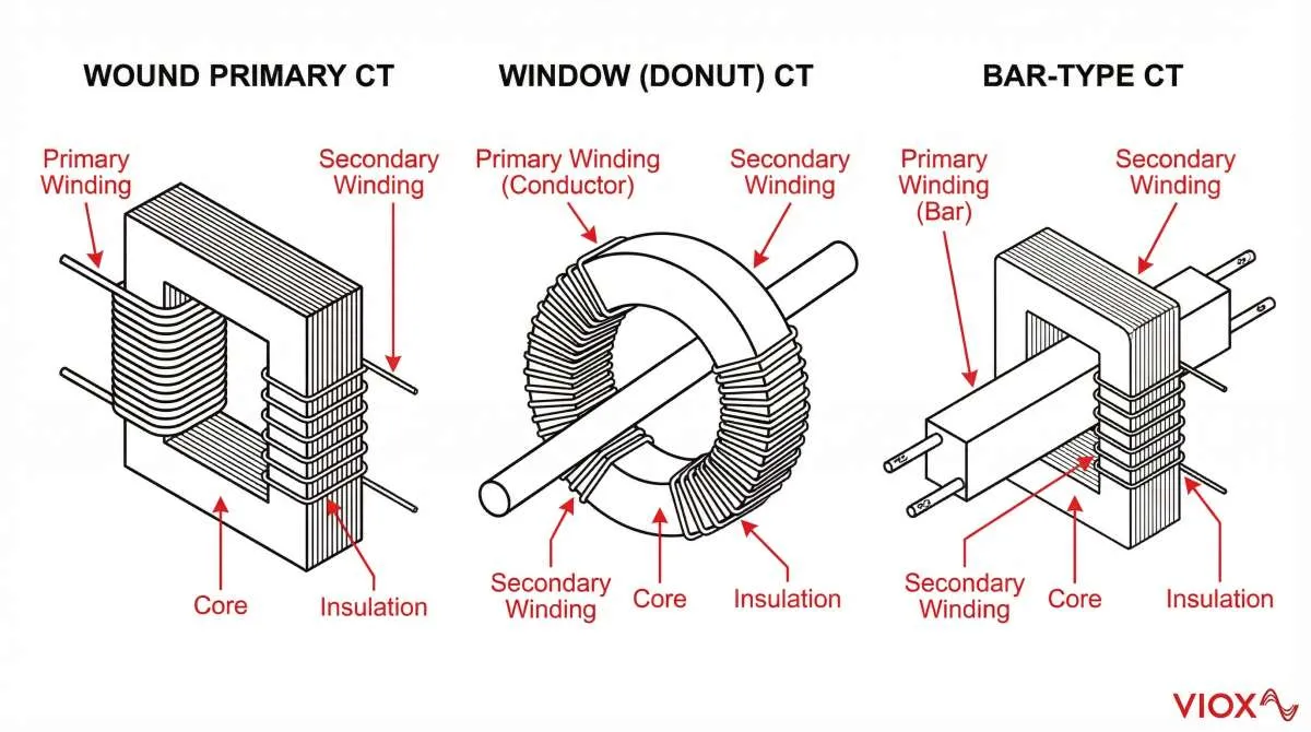
Οι μετασχηματιστές ρεύματος και οι μετασχηματιστές τάσης κατασκευάζονται σε διακριτές φυσικές μορφές για να ταιριάζουν με τις συγκεκριμένες λειτουργίες μέτρησης και τις απαιτήσεις εγκατάστασης. Οι Μ/Σ ρεύματος εμφανίζονται συνήθως ως τύποι παραθύρου (ντόνατ) για εύκολη εγκατάσταση γύρω από υπάρχοντες αγωγούς, σχέδια πρωτεύοντος τυλίγματος για χαμηλότερες περιοχές ρεύματος, παραλλαγές τύπου ράβδου για στιβαρή μηχανική κατασκευή και διαμορφώσεις διέλευσης για εφαρμογές εκ των υστέρων τοποθέτησης. Οι Μ/Σ τάσης είναι συνήθως ηλεκτρομαγνητικοί (επαγωγικοί) μετασχηματιστές για τάσεις έως 36 kV, μετασχηματιστές τάσης πυκνωτή (CVT) για συστήματα εξαιρετικά υψηλής τάσης και εκδόσεις χυτής ρητίνης ή εμβάπτισης σε λάδι για σκληρές περιβαλλοντικές συνθήκες. Κάθε τύπος κατασκευής εξισορροπεί την ακρίβεια, το κόστος, το μέγεθος και την περιβαλλοντική ανθεκτικότητα για να ταιριάζει σε διαφορετικές εφαρμογές συστήματος ισχύος.
Κλάσεις Ακρίβειας και Πρότυπα (IEC έναντι ANSI)
Οι μετασχηματιστές οργάνων διέπονται από διεθνή και περιφερειακά πρότυπα που καθορίζουν την απόδοση ακρίβειας, τις μεθόδους δοκιμής και τα συστήματα ονομαστικής τιμής. Τα δύο κυρίαρχα πλαίσια είναι IEC (Διεθνής Ηλεκτροτεχνική Επιτροπή) πρότυπα, που χρησιμοποιούνται παγκοσμίως, και ANSI/IEEE (Αμερικανικό Εθνικό Ινστιτούτο Προτύπων/Ινστιτούτο Ηλεκτρολόγων και Ηλεκτρονικών Μηχανικών) πρότυπα, που επικρατούν στη Βόρεια Αμερική.
Πρότυπα IEC για Μ/Σ Ρεύματος και Μ/Σ Τάσης
- IEC 61869‑2: Πρόσθετες απαιτήσεις για μετασχηματιστές ρεύματος
- IEC 61869‑3: Πρόσθετες απαιτήσεις για μετασχηματιστές δυναμικού (τάσης)
Κλάσεις Ακρίβειας Μ/Σ Ρεύματος σύμφωνα με το IEC 61869‑2
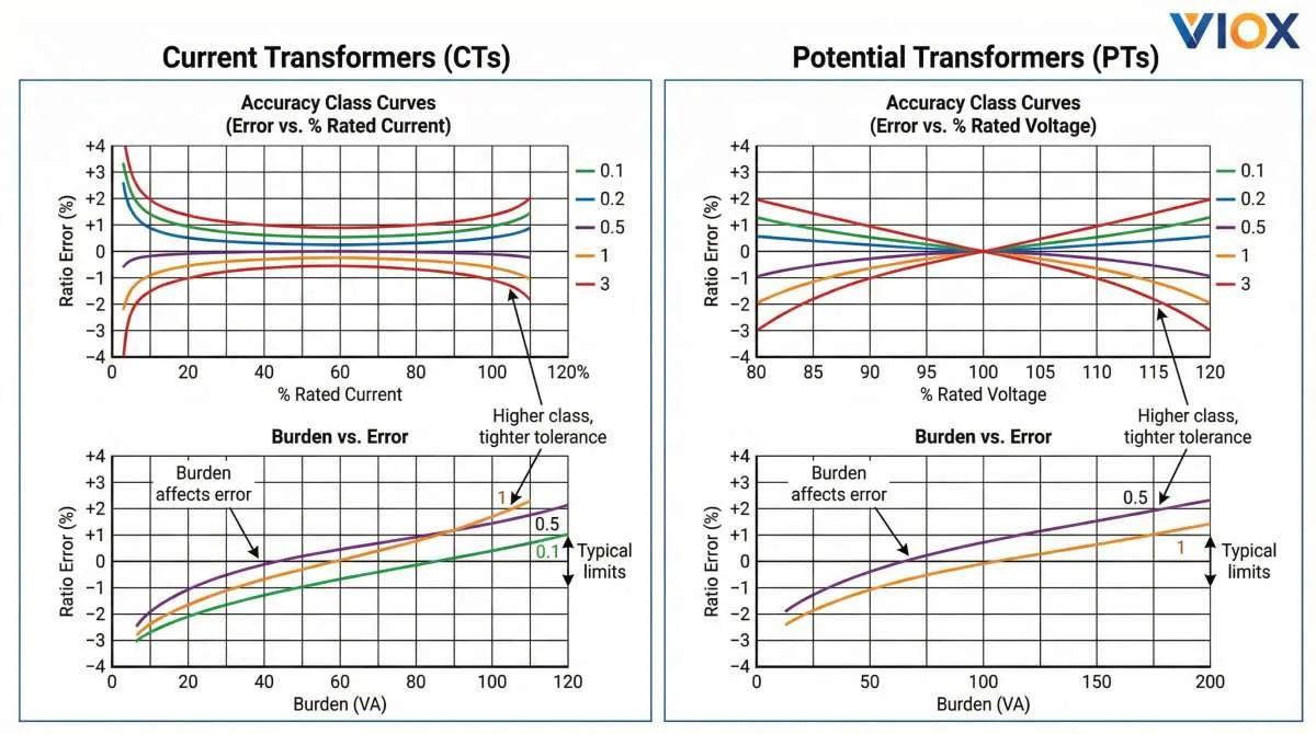
- Τυπικές κλάσεις: 0.1, 0.2, 0.5, 1, 3 (ποσοστιαίο σφάλμα λόγου στο ονομαστικό ρεύμα)
- Ειδικές κλάσεις: 0.2S, 0.5S – εκτεταμένη ακρίβεια σε ένα ευρύτερο εύρος ρεύματος (1% έως 120% του ονομαστικού ρεύματος)
- Κλάσεις P: P, PR (με υπολειμματικότητα) – ορίζονται από σύνθετα όρια σφάλματος στο ονομαστικό ρεύμα ορίου ακρίβειας (π.χ., 5P20, 10P20)
- Κλάσεις TP: TPX, TPY, TPZ – για απαιτήσεις μεταβατικής απόδοσης σε συστήματα προστασίας υψηλής ταχύτητας
Κλάσεις Ακρίβειας Μ/Σ Τάσης σύμφωνα με το IEC 61869‑3
Κλάσεις Μετρήσεων: 0,1, 0,2, 0,5, 1, 3 (ποσοστιαίο σφάλμα τάσης και γωνία μετατόπισης φάσης στην ονομαστική τάση και φορτίο)
Κλάσεις Προστασίας: P, PR – παρόμοια με τους Μ/Σ έντασης αλλά εφαρμόζονται σε μετασχηματιστές τάσης για εφαρμογές προστασίας
Πρότυπα ANSI/IEEE για Μ/Σ Έντασης και Μ/Σ Τάσης
IEEE C57.13 (και τα παράγωγά του) είναι το κύριο πρότυπο για μετασχηματιστές οργάνων στη Βόρεια Αμερική.
Κλάσεις Ακρίβειας Μ/Σ Έντασης σύμφωνα με το IEEE C57.13
- 0.3%, 0.6%, 1.2% – που αντιστοιχούν σε φορτία B‑0.1, B‑0.2, B‑0.5, B‑1, B‑2, B‑4, B‑8
- Κλάση C: C100, C200, C400, C800 – ο αριθμός υποδεικνύει την τάση δευτερεύοντος κυκλώματος στο τυπικό φορτίο (π.χ., το C200 παρέχει 200 V στα 100 A δευτερεύοντος κυκλώματος με φορτίο 2‑Ω)
- Κλάση T: Οι Μ/Σ έντασης κλάσης T έχουν υψηλότερη μαγνητική διαρροή και απαιτούν δοκιμές για τον προσδιορισμό των συντελεστών διόρθωσης λόγου
Κλάσεις Ακρίβειας Μ/Σ Τάσης σύμφωνα με το IEEE C57.13
Ακρίβεια Μετρήσεων: 0.3%, 0.6%, 1.2% – όρια σφάλματος τάσης σε καθορισμένα φορτία και εύρη τάσης (90% έως 110% της ονομαστικής τάσης)
Ομάδες IEEE: Οι Μ/Σ τάσης κατηγοριοποιούνται σε ομάδες (π.χ., Ομάδα 1, Ομάδα 2) με βάση το σύστημα μόνωσής τους και τις δυνατότητες υπέρτασης, οι οποίες υπαγορεύουν τους συντελεστές συνεχούς και βραχείας διάρκειας υπέρτασης.
Ισοδύναμα μεταξύ Προτύπων
- Μετρήσεις Μ/Σ Έντασης: IEC 0.2 ≈ ANSI 0.3%; IEC 0.5 ≈ ANSI 0.6%; IEC 1 ≈ ANSI 1.2%
- Προστασία Μ/Σ Έντασης: IEC 5P20 στα 50 VA ≈ C200; IEC 10P20 στα 100 VA ≈ C400
- Μετρήσεις Μ/Σ Τάσης: IEC 0.2 ≈ ANSI 0.3%; IEC 0.5 ≈ ANSI 0.6%
Σημασία των Παραμέτρων Φορτίου
Και στα συστήματα IEC και ANSI, οι κλάσεις ακρίβειας είναι έγκυρες μόνο σε καθορισμένα φορτία. Το συνολικό φορτίο δευτερεύοντος κυκλώματος (συμπεριλαμβανομένης της σύνθετης αντίστασης του μετρητή/ρελέ, της αντίστασης των καλωδίων και της αντίστασης επαφής) πρέπει να υπολογιστεί και να διατηρηθεί εντός του ονομαστικού φορτίου του μετασχηματιστή για να διατηρηθεί η δηλωμένη ακρίβεια. Η υπέρβαση του ονομαστικού φορτίου μπορεί να προκαλέσει κορεσμό (Μ/Σ έντασης) ή υπερβολική πτώση τάσης (Μ/Σ τάσης), οδηγώντας σε σφάλματα μέτρησης ή δυσλειτουργία της προστασίας.
Η VIOX Electric παρέχει λεπτομερή τεχνικά δελτία που καθορίζουν τις κλάσεις ακρίβειας, τα ονομαστικά φορτία και τις δυνατότητες υπερέντασης/υπέρτασης σύμφωνα με τα πρότυπα IEC και ANSI/IEEE, επιτρέποντας τη σωστή επιλογή για τη συγκεκριμένη εφαρμογή σας.
Εφαρμογές σε Μετρήσεις, Προστασία και Παρακολούθηση
Οι μετασχηματιστές έντασης και οι μετασχηματιστές τάσης εξυπηρετούν συμπληρωματικούς ρόλους στις τρεις κύριες λειτουργίες των μετασχηματιστών οργάνων: μέτρηση (εσόδων και λειτουργική), προστασία (ασφάλεια συστήματος και εξοπλισμού) και παρακολούθηση (ποιότητα ισχύος και υγεία συστήματος).
Εφαρμογές Μετρήσεων
Μ/Σ Έντασης για Μέτρηση Ενέργειας: Οι Μ/Σ έντασης παρέχουν την είσοδο ρεύματος για τους μετρητές watt‑ώρας, επιτρέποντας την ακριβή χρέωση για τις εταιρείες κοινής ωφέλειας και την υπομέτρηση για τις βιομηχανικές εγκαταστάσεις. Οι Μ/Σ έντασης κατηγορίας μέτρησης (IEC 0.2/0.5, ANSI 0.3%/0.6%) εξασφαλίζουν ελάχιστα σφάλματα λόγου και γωνίας φάσης σε κανονικά ρεύματα φορτίου.
Μ/Σ Τάσης για Μέτρηση Τάσης: Οι Μ/Σ τάσης παρέχουν την αναφορά τάσης για τους ίδιους μετρητές, ολοκληρώνοντας τον υπολογισμό της ισχύος (P = V×I×cosθ). Χωρίς τους Μ/Σ τάσης, οι διακυμάνσεις της τάσης θα εισήγαγαν σημαντικά σφάλματα μέτρησης.
Εφαρμογές Προστασίας
Μ/Σ Έντασης για Ρελέ: Οι Μ/Σ έντασης κατηγορίας προστασίας (IEC 5P20, 10P20; ANSI C200, C400) τροφοδοτούν σήματα ρεύματος σε προστατευτικά ρελέ που ανιχνεύουν σφάλματα (υπερένταση, διαφορική, απόσταση). Πρέπει να διατηρούν την ακρίβεια μέχρι το ρεύμα ορίου ακρίβειας (π.χ., 20× ονομαστικό ρεύμα) για να εξασφαλίσουν αξιόπιστη απόζευξη.
Μ/Σ Τάσης για Προστασία Βασισμένη στην Τάση: Οι Μ/Σ τάσης παρέχουν σήματα τάσης για ρελέ υποτάσης, υπέρτασης και προστασίας απόστασης. Πρέπει να αντέχουν προσωρινές υπερτάσεις κατά τη διάρκεια διαταραχών του συστήματος χωρίς να κορεστούν ή να χάσουν την ακρίβειά τους.
Εφαρμογές Παρακολούθησης και Ελέγχου
Μ/Σ Έντασης για Καταγραφή Προφίλ Φορτίου: Οι Μ/Σ έντασης που συνδέονται με καταγραφείς δεδομένων ή συστήματα SCADA παρακολουθούν τα πρότυπα φορτίου, τις αιχμές ζήτησης και τον συντελεστή ισχύος για βελτιστοποίηση της λειτουργίας.
Μ/Σ Τάσης για Ανάλυση Ποιότητας Ισχύος: Οι Μ/Σ τάσης επιτρέπουν την παρακολούθηση των βυθίσεων τάσης, των διογκώσεων, των αρμονικών και της ανισορροπίας—κρίσιμα για ευαίσθητες βιομηχανικές διεργασίες και τη συμμόρφωση με τα πρότυπα ποιότητας ισχύος.
Ολοκληρωμένα Συστήματα: Στους σύγχρονους ψηφιακούς υποσταθμούς, οι Μ/Σ έντασης και οι Μ/Σ τάσης τροφοδοτούν μονάδες συγχώνευσης που ψηφιοποιούν αναλογικά σήματα για συστήματα προστασίας και ελέγχου που βασίζονται στο πρότυπο IEC 61850.
Εξειδικευμένες εφαρμογές
Μ/Σ Έντασης για Προστασία Κινητήρα: Οι Μ/Σ έντασης παρακολουθούν το ρεύμα του κινητήρα για προστασία από υπερφόρτωση, μπλοκαρισμένο ρότορα και απώλεια φάσης.
Μ/Σ Τάσης για Συγχρονισμό: Οι Μ/Σ τάσης παρέχουν ακριβείς πληροφορίες τάσης και γωνίας φάσης για τον συγχρονισμό των γεννητριών με το δίκτυο.
Μ/Σ Έντασης/Τάσης για Ανανεώσιμες Πηγές Ενέργειας: Σε ηλιακά και αιολικά πάρκα, οι μετασχηματιστές οργάνων παρακολουθούν την έξοδο του αντιστροφέα, τα σημεία σύνδεσης στο δίκτυο και τα συστήματα συλλογής.
Οι σειρές προϊόντων Μ/Σ έντασης και Μ/Σ τάσης της VIOX Electric καλύπτουν όλες αυτές τις εφαρμογές, με σχέδια βελτιστοποιημένα για ακρίβεια, αξιοπιστία και μακροπρόθεσμη σταθερότητα σε διάφορα λειτουργικά περιβάλλοντα.
Πώς να Επιλέξετε τον Κατάλληλο Μετασχηματιστή για το Σύστημά σας
Η επιλογή του κατάλληλου μετασχηματιστή έντασης ή μετασχηματιστή τάσης απαιτεί προσεκτική εξέταση αρκετών βασικών παραμέτρων:
Βασικά κριτήρια επιλογής
1. Ονομαστική Τιμή Πρωτεύοντος Κυκλώματος: Αντιστοιχίστε το πρωτεύον ρεύμα (Μ/Σ έντασης) ή την τάση (Μ/Σ τάσης) του μετασχηματιστή στις λειτουργικές τιμές του συστήματός σας. Λάβετε υπόψη τόσο το κανονικό φορτίο όσο και τις μέγιστες συνθήκες σφάλματος.
- Μετρήσεις: IEC 0.2/0.5 ή ANSI 0.3%/0.6% για ακρίβεια χρέωσης
- Προστασία: IEC 5P20/10P20 ή ANSI C200/C400 για αξιόπιστη ανίχνευση σφαλμάτων
3. Ονομαστική Τιμή Φορτίου: Υπολογίστε τη συνολική σύνθετη αντίσταση του δευτερεύοντος κυκλώματος (καλώδια, μετρητές, ρελέ) και επιλέξτε έναν μετασχηματιστή με επαρκή ονομαστική τιμή VA για να διατηρήσετε την ακρίβεια.
4. Επίπεδο Μόνωσης: Βεβαιωθείτε ότι η ονομαστική τάση μόνωσης του μετασχηματιστή υπερβαίνει τη μέγιστη τάση του συστήματός σας, συμπεριλαμβανομένων των παροδικών υπερτάσεων.
5. Περιβαλλοντικές Συνθήκες: Λάβετε υπόψη το εύρος θερμοκρασίας, την υγρασία, το υψόμετρο και την προστασία εισόδου (βαθμός IP) για τη θέση εγκατάστασης.
Συνηθισμένα λάθη επιλογής που πρέπει να αποφεύγετε
- Υποδιαστασιολόγηση Μ/Σ Έντασης για ρεύματα σφάλματος, που οδηγεί σε κορεσμό και αποτυχία προστασίας
- Αγνοώντας τους υπολογισμούς φορτίου, προκαλώντας υποβάθμιση της ακρίβειας
- Ανάμιξη προτύπων IEC και ANSI χωρίς κατανόηση της ισοδυναμίας
- Παραμέληση των απαιτήσεων ασφαλείας (γείωση, προστασία ανοιχτού κυκλώματος για Μ/Σ Έντασης)
Υποστήριξη Επιλογής VIOX
Η VIOX Electric παρέχει ολοκληρωμένη τεχνική υποστήριξη για να σας βοηθήσει να επιλέξετε τον βέλτιστο Μ/Σ Έντασης ή Μ/Σ Τάσης για την εφαρμογή σας. Οι ειδικοί μας μπορούν να σας βοηθήσουν με υπολογισμούς φορτίου, ερμηνείες προτύπων και απαιτήσεις προσαρμοσμένου σχεδιασμού.
Συχνές ερωτήσεις (FAQ)
Ε1: Μπορώ να χρησιμοποιήσω έναν μετασχηματιστή ρεύματος για να μετρήσω την τάση ή έναν μετασχηματιστή τάσης για να μετρήσω το ρεύμα;
Όχι. Οι Μ/Σ ρεύματος (CTs) είναι σχεδιασμένοι ειδικά για τη μέτρηση ρεύματος και πρέπει να συνδέονται σε σειρά με τον αγωγό. Οι Μ/Σ τάσης (PTs) είναι σχεδιασμένοι για τη μέτρηση τάσης και συνδέονται παράλληλα. Η εναλλακτική χρήση τους θα οδηγήσει σε λανθασμένες ενδείξεις, πιθανή ζημιά στον εξοπλισμό και κινδύνους για την ασφάλεια.
Ε2: Τι συμβαίνει αν ανοίξω το δευτερεύον κύκλωμα ενός Μ/Σ Έντασης ενώ το πρωτεύον είναι ενεργοποιημένο;
Το άνοιγμα του δευτερεύοντος ενός Μ/Σ ρεύματος (CT) υπό φορτίο προκαλεί τον κορεσμό του μαγνητικού πυρήνα, επάγοντας επικίνδυνα υψηλές τάσεις (αρκετές χιλιάδες Volt) στα ανοικτά άκρα. Αυτό μπορεί να οδηγήσει σε διάσπαση μόνωσης, δημιουργία τόξου, πυρκαγιά ή έκρηξη του μετασχηματιστή. Να βραχυκυκλώνετε πάντα τα αχρησιμοποίητα δευτερεύοντα των Μ/Σ ρεύματος.
Ε3: Πώς μπορώ να μετατρέψω μεταξύ των κλάσεων ακρίβειας IEC και ANSI;
Προσεγγιστικές ισοδυναμίες: IEC 0.2 ≈ ANSI 0.3%; IEC 0.5 ≈ ANSI 0.6%; IEC 1 ≈ ANSI 1.2%. Για μετασχηματιστές ρεύματος προστασίας, IEC 5P20 στα 50 VA ≈ C200, και IEC 10P20 στα 100 VA ≈ C400. Να συμβουλεύεστε πάντα τα δεδομένα του κατασκευαστή για την ακριβή απόδοση υπό το συγκεκριμένο φορτίο σας.
Ε4: Μπορώ να συνδέσω πολλαπλούς μετρητές ή ρελέ σε έναν Μ/Σ Έντασης ή Μ/Σ Τάσης;
Ναι, αλλά το συνολικό φορτίο (άθροισμα όλων των συνδεδεμένων συσκευών συν την αντίσταση των καλωδίων) δεν πρέπει να υπερβαίνει το ονομαστικό φορτίο του μετασχηματιστή. Η υπέρβαση του ονομαστικού φορτίου υποβαθμίζει την ακρίβεια και, για τους Μ/Σ Έντασης, μπορεί να προκαλέσει πρόωρο κορεσμό κατά τη διάρκεια σφαλμάτων.
Ε5: Κάθε πότε πρέπει να ελέγχονται ή να βαθμονομούνται οι μετασχηματιστές οργάνων;
Η αρχική επαλήθευση θα πρέπει να πραγματοποιείται μετά την εγκατάσταση. Τα περιοδικά διαστήματα δοκιμών εξαρτώνται από την εφαρμογή: η μέτρηση εσόδων μπορεί να απαιτεί ετήσια βαθμονόμηση, ενώ οι μετασχηματιστές ρεύματος/τάσης προστασίας σε σταθερά περιβάλλοντα μπορεί να δοκιμάζονται κάθε 5-10 χρόνια. Ακολουθήστε τις οδηγίες της εταιρείας κοινής ωφέλειας ή τις κανονιστικές οδηγίες.
Ε6: Ποια είναι η διαφορά μεταξύ ενός μετασχηματιστή τάσης (PT) και ενός μετασχηματιστή τάσης πυκνωτή (CVT);
Ένας Μ/Σ Εντάσεως (PT) είναι ένας ηλεκτρομαγνητικός μετασχηματιστής που υποβιβάζει άμεσα την τάση. Ένας Μ/Σ Χωρητικού Τύπου (CVT) χρησιμοποιεί έναν χωρητικό διαιρέτη ακολουθούμενο από έναν μαγνητικό μετασχηματιστή, καθιστώντας τον πιο οικονομικό για συστήματα υπερυψηλής τάσης (EHV) (συνήθως ≥72,5 kV). Οι CVT χρησιμοποιούνται επίσης ως πυκνωτές σύζευξης για επικοινωνία μέσω φέροντος ρεύματος γραμμής μεταφοράς.
Ε7: Γιατί πρέπει να γειώνονται τα δευτερεύοντα κυκλώματα των Μ/Σ Έντασης και Μ/Σ Τάσης;
Η γείωση ενός δευτερεύοντος ακροδέκτη παρέχει ένα σταθερό σημείο αναφοράς, αποτρέπει τα αιωρούμενα δυναμικά που θα μπορούσαν να θέσουν σε κίνδυνο το προσωπικό και περιορίζει τις επαγόμενες τάσεις από εξωτερικές πηγές. Η σωστή γείωση είναι απαραίτητη για την ασφάλεια και την ακριβή μέτρηση.
Συμπέρασμα: Συνεργασία με τη VIOX για Αξιόπιστους Μετασχηματιστές Οργάνων
Η κατανόηση των θεμελιωδών διαφορών μεταξύ των μετασχηματιστών ρεύματος και των μετασχηματιστών τάσης είναι απαραίτητη για το σχεδιασμό ασφαλών, ακριβών και αξιόπιστων ηλεκτρικών συστημάτων ισχύος. Οι Μ/Σ Έντασης, που συνδέονται σε σειρά, μετατρέπουν υψηλά ρεύματα σε τυποποιημένα σήματα χαμηλού ρεύματος για μέτρηση και προστασία. Οι Μ/Σ Τάσης, που συνδέονται παράλληλα, υποβιβάζουν τις υψηλές τάσεις σε ασφαλή, μετρήσιμα επίπεδα. Οι διακριτοί σχεδιασμοί, οι κλάσεις ακρίβειας και οι απαιτήσεις ασφαλείας τους πρέπει να λαμβάνονται προσεκτικά υπόψη κατά την επιλογή και την εγκατάσταση.
Η VIOX Electric, ως κορυφαίος κατασκευαστής ηλεκτρικού εξοπλισμού, προσφέρει μια ολοκληρωμένη σειρά Μ/Σ Έντασης και Μ/Σ Τάσης που πληρούν τα διεθνή πρότυπα IEC και ANSI/IEEE. Τα προϊόντα μας είναι σχεδιασμένα για ακρίβεια, ανθεκτικότητα και απόδοση σε διάφορες εφαρμογές - από υποσταθμούς κοινής ωφέλειας έως βιομηχανικές εγκαταστάσεις και εγκαταστάσεις ανανεώσιμης ενέργειας.
Όταν χρειάζεστε μετασχηματιστές οργάνων που προσφέρουν ασυμβίβαστη ακρίβεια και αξιοπιστία, συνεργαστείτε με τη VIOX. Επικοινωνήστε με την τεχνική μας ομάδα για εξατομικευμένη υποστήριξη στην επιλογή των κατάλληλων μετασχηματιστών για τις συγκεκριμένες απαιτήσεις σας.
