")
Η κλήση έρχεται στις 2:14 π.μ. Ένας κινητήρας μεταφορικής ταινίας στη γραμμή συσκευασίας λειτουργεί ανάποδα, στέλνοντας κουτιά προϊόντων να συγκρούονται μεταξύ τους. Ο τεχνικός συντήρησης ορκίζεται ότι ακολούθησε το ηλεκτρολογικό σχέδιο όταν αντικατέστησε τον έκκεντρο διακόπτη χθες το απόγευμα. Αλλά κάπου μεταξύ του σχηματικού και της λωρίδας ακροδεκτών, δύο φάσεις διασταυρώθηκαν—και τώρα η νυχτερινή βάρδια διαλογή κουτιά με το χέρι, ενώ η ημερήσια βάρδια υπολογίζει το κόστος διακοπής λειτουργίας.
Η σωστή καλωδίωση ενός έκκεντρου διακόπτη την πρώτη φορά δεν είναι περίπλοκη, αλλά απαιτεί κατανόηση των συμβάσεων ακροδεκτών, ακολουθώντας το σωστό διάγραμμα για την εφαρμογή σας και επαληθεύοντας κάθε σύνδεση πριν κλείσετε την πόρτα του πίνακα. Αυτός ο οδηγός σας καθοδηγεί σε όλη τη διαδικασία—από το κλείδωμα ασφαλείας έως την τελική δοκιμή—με ηλεκτρολογικά σχέδια για τις πιο κοινές βιομηχανικές εφαρμογές: απλή απομόνωση ON/OFF, επιλογείς 3 θέσεων, αντιστροφή τριφασικού κινητήρα, αλλαγή ισχύος και εναλλαγή μέτρησης.
Είτε είστε ένας μαθητευόμενος ηλεκτρολόγος που εγκαθιστά τον πρώτο σας πίνακα ελέγχου είτε ένας έμπειρος τεχνικός που αντικαθιστά έναν αποτυχημένο διακόπτη σε ένα υπάρχον σύστημα, αυτή η βήμα προς βήμα αναφορά θα σας βοηθήσει να κάνετε σωστά την καλωδίωση.
Πρώτα η Ασφάλεια: Λίστα Ελέγχου Πριν την Καλωδίωση
Πριν απογυμνώσετε ένα μόνο καλώδιο, ολοκληρώστε αυτά τα βήματα ασφαλείας:
Απενεργοποιήστε και Κλειδώστε το Κύκλωμα: Απενεργοποιήστε τον αυτόματο διακόπτη, εφαρμόστε κλείδωμα/σήμανση και επαληθεύστε με έναν ελεγκτή τάσης σε όλες τις φάσεις και τον ουδέτερο. Μην εμπιστεύεστε ποτέ μόνο τη θέση του διακόπτη.
Επαληθεύστε ότι οι Ονομαστικές Τιμές Αντιστοιχούν στο Φορτίο σας: Ελέγξτε την πινακίδα για το ονομαστικό ρεύμα (Ie), την τάση (Ue) και την κατηγορία χρήσης (AC-21 για ωμικό, AC-23 για κινητήρες). Για κινητήρες, επιλέξτε 1,5× το ρεύμα πλήρους φορτίου για να χειριστείτε την εισροή εκκίνησης.
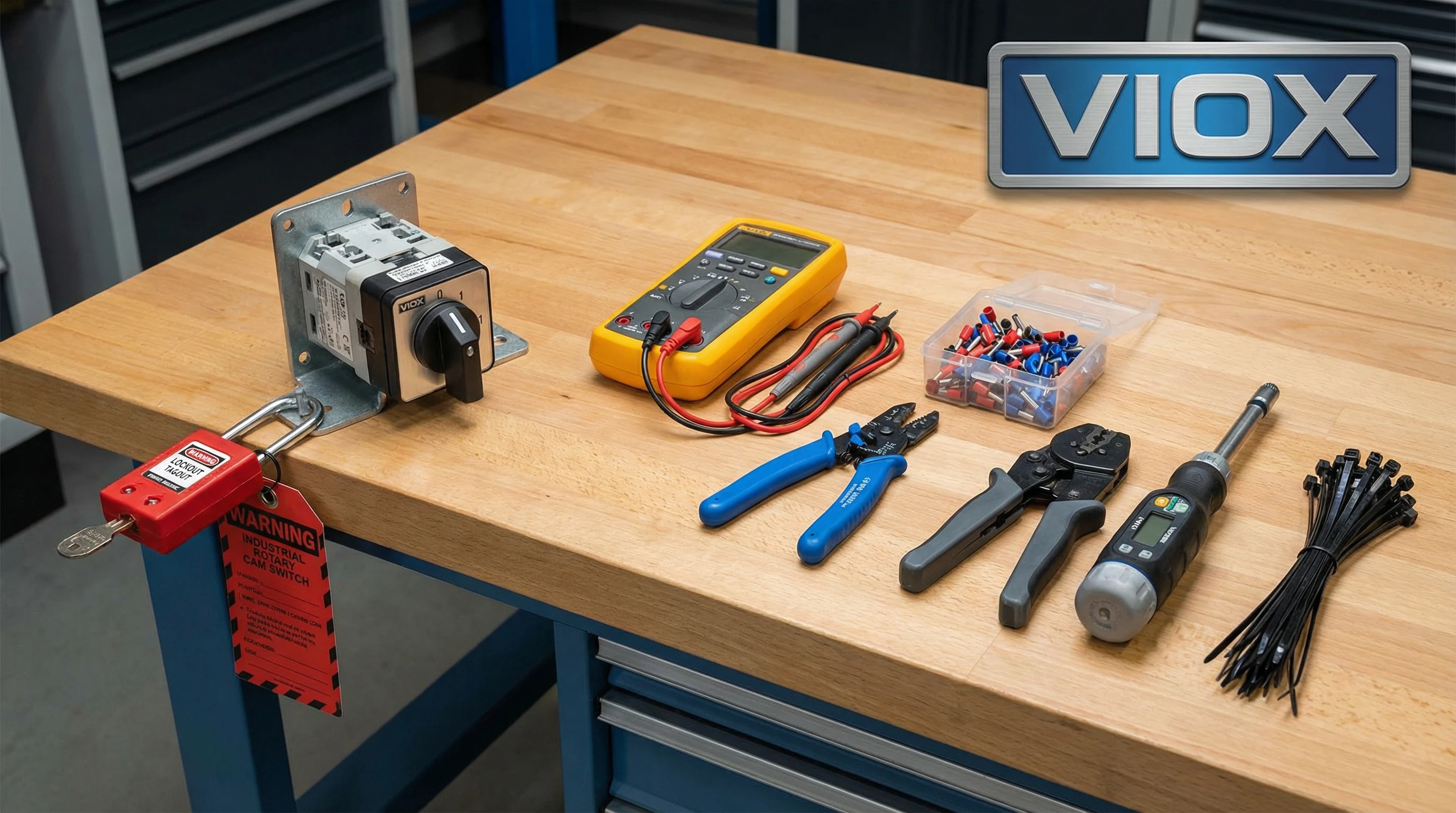
Συγκεντρώστε Εργαλεία: Απογυμνωτές καλωδίων, μονωμένοι ακροδέκτες, εργαλείο πρεσαρίσματος, κατσαβίδι ροπής, πολύμετρο, δεματικά καλωδίων και ετικέτες. Οι εγκαταστάσεις IEC απαιτούν ακροδέκτες σε πολύκλωνο καλώδιο.
Προσδιορίστε τα Χρώματα των Καλωδίων: IEC: Καφέ (L1), Μαύρο (L2), Γκρι (L3), Μπλε (N), Πράσινο-Κίτρινο (PE). NEC: Μαύρο (L1), Κόκκινο (L2), Μπλε (L3), Λευκό (N), Πράσινο (Γείωση).
Επαληθεύστε τη Γείωση: Συνδέστε το περίβλημα του διακόπτη με την προστατευτική γείωση. Επιβεβαιώστε τη συνέχεια με τη γείωση του πίνακα.
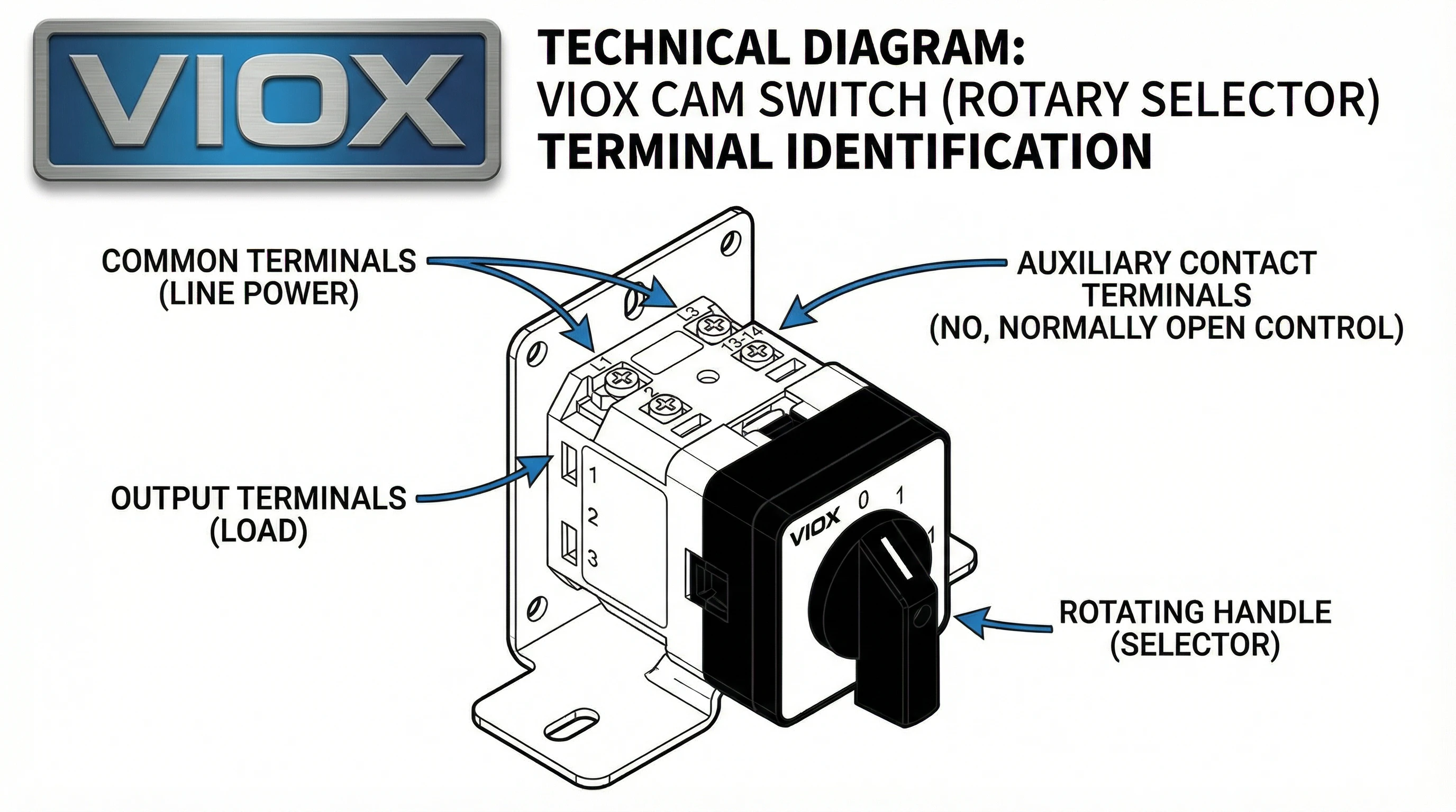
Κατανόηση των Ακροδεκτών του Έκκεντρου Διακόπτη
Οι ακροδέκτες των έκκεντρων διακοπτών δεν είναι τυποποιημένοι μεταξύ των κατασκευαστών, γι' αυτό συμβαίνουν λάθη στην καλωδίωση. Η εκμάθηση του τρόπου ανάγνωσης της πινακίδας και ο προσδιορισμός των λειτουργιών των ακροδεκτών αποτρέπει τα πιο κοινά σφάλματα εγκατάστασης.
Κοινοί Ακροδέκτες (Είσοδος): Ο κοινός ακροδέκτης είναι όπου συνδέετε την εισερχόμενη ισχύ ή σήμα. Σε έναν επιλογέα 3 θέσεων (1-0-2), ο κοινός ακροδέκτης συχνά φέρει την ένδειξη “0” ή “C”. Στους διακόπτες αντιστροφής κινητήρα, θα δείτε τρεις κοινούς ακροδέκτες—έναν για κάθε φάση—με την ένδειξη L1, L2, L3 ή U, V, W. Η ισχύς ρέει σε αυτούς τους ακροδέκτες.
Ακροδέκτες Εξόδου (Κυκλώματα με Διακόπτη): Οι ακροδέκτες εξόδου συνδέονται με τα φορτία που ελέγχονται. Σε έναν επιλογέα 3 θέσεων, οι έξοδοι συνήθως φέρουν την ένδειξη “1” και “2” (ή “A” και “B”). Όταν η λαβή είναι στη Θέση 1, ο κοινός συνδέεται με την Έξοδο 1. Όταν η λαβή είναι στη Θέση 2, ο κοινός συνδέεται με την Έξοδο 2. Στην κεντρική θέση OFF, ο κοινός αποσυνδέεται και από τις δύο εξόδους.
Βοηθητικές επαφές: Ορισμένοι έκκεντροι διακόπτες περιλαμβάνουν βοηθητικές επαφές—μικρές πρόσθετες επαφές με ονομαστική τιμή για κυκλώματα σηματοδότησης (συνήθως 3A-6A). Αυτές χρησιμοποιούνται για την αποστολή σημάτων κατάστασης σε PLC, ενδεικτικές λυχνίες ή κυκλώματα αλληλομπλοκαρίσματος. Οι βοηθητικοί ακροδέκτες συνήθως φέρουν ξεχωριστή σήμανση με αριθμούς όπως 13-14 (επαφή NO) ή 21-22 (επαφή NC), ακολουθώντας τις συμβάσεις IEC 60947-5-1.
Ανάγνωση του Κωδικού Προγράμματος: Πολλοί βιομηχανικοί έκκεντροι διακόπτες χρησιμοποιούν έναν κωδικό προγράμματος ή έναν πίνακα μεταγωγής τυπωμένο στο πλάι ή στο φύλλο δεδομένων. Αυτός ο κωδικός ορίζει ποιες επαφές κλείνουν σε κάθε θέση της λαβής. Για παράδειγμα, ένας κωδικός προγράμματος “0-1-2” σημαίνει ότι η Θέση 0 ανοίγει όλες τις επαφές, η Θέση 1 κλείνει ένα σύνολο, η Θέση 2 κλείνει ένα διαφορετικό σύνολο. Να διασταυρώνετε πάντα τον κωδικό προγράμματος με το ηλεκτρολογικό σας σχέδιο πριν ξεκινήσετε.
Γρήγορη Αναφορά: Αρίθμηση Ακροδεκτών ανά Μάρκα
| Κατασκευαστής | Κοινός(οί) Ακροδέκτης(ες) | Ακροδέκτες Εξόδου | Σημειώσεις |
| Γενικός/IEC | 0, C ή L1/L2/L3 | 1, 2, 3, 4 (ή A, B, C) | Οι αριθμοί θέσεων συχνά ταιριάζουν με τους ακροδέκτες εξόδου |
| ABB | L1, L2, L3 (είσοδος) | T1, T2, T3 (έξοδος) | Ακολουθήστε τις συμβάσεις IEC· συμβουλευτείτε το διάγραμμα ακροδεκτών |
| Schneider | 1, 3, 5 (είσοδος) | 2, 4, 6 (έξοδος) | Μονοί αριθμοί = είσοδος, Ζυγοί = έξοδος |
| VIOX LW26 | L1, L2, L3 (είσοδος) | 1, 2, 3 ή T1, T2, T3 (έξοδος) | Διάγραμμα ακροδεκτών στο σώμα του διακόπτη· κωδικός προγράμματος στην ετικέτα |
Να συμβουλεύεστε πάντα το ηλεκτρολογικό σχέδιο του κατασκευαστή. Σε περίπτωση αμφιβολίας, χρησιμοποιήστε έναν ελεγκτή συνέχειας: με τον διακόπτη απενεργοποιημένο, περιστρέψτε τη λαβή σε κάθε θέση και ελέγξτε ποιοι ακροδέκτες εμφανίζουν συνέχεια. Χαρτογραφήστε το πρόγραμμα μεταγωγής χειροκίνητα εάν η τεκμηρίωση δεν είναι σαφής.
Ηλεκτρολογικά Σχέδια ανά Εφαρμογή
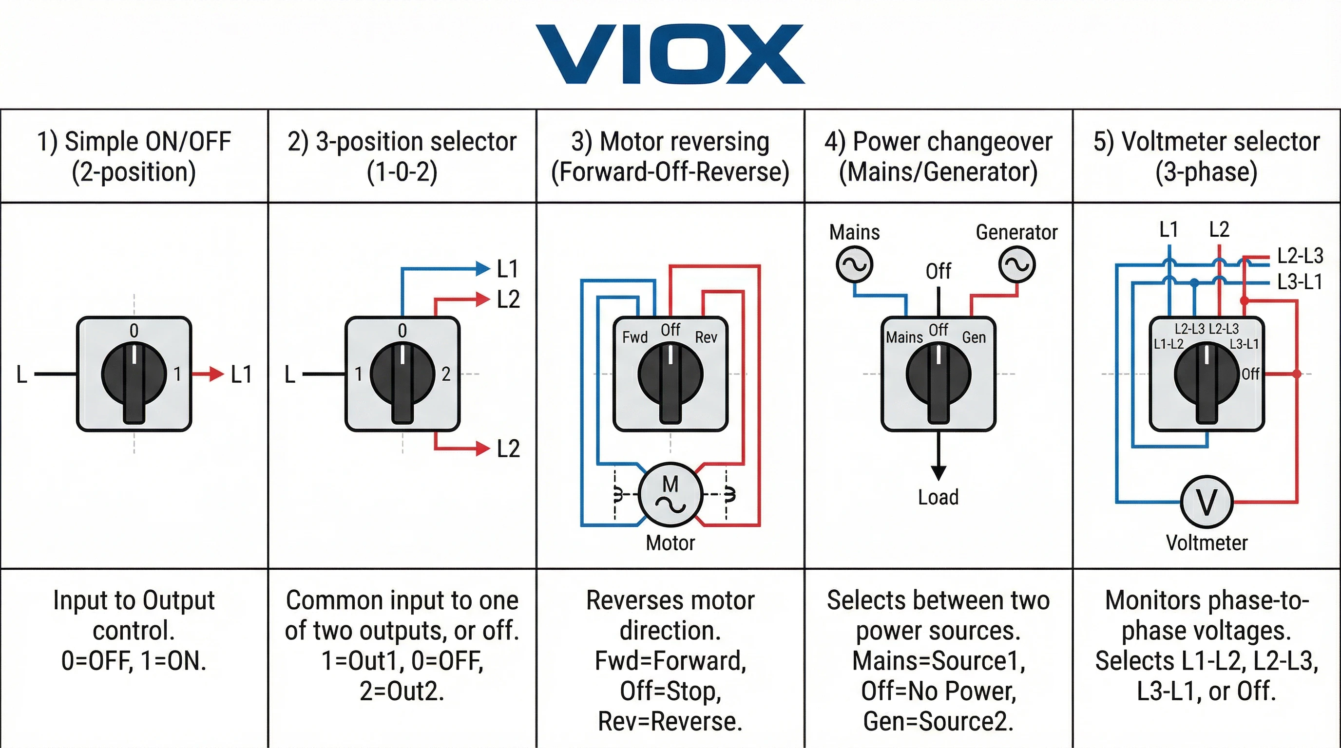
Εδώ είναι τα πέντε πιο κοινά σενάρια καλωδίωσης έκκεντρου διακόπτη που θα συναντήσετε σε βιομηχανικές και εμπορικές εγκαταστάσεις. Κάθε ένα περιλαμβάνει συνδέσεις ακροδεκτών και τυπικές εφαρμογές.
1. Απλός Διακόπτης ON/OFF (Απομόνωση/Έλεγχος Φορτίου)
Η απλούστερη διαμόρφωση: ένας έκκεντρος διακόπτης 2 θέσεων που ανοίγει και κλείνει ένα ή περισσότερα κυκλώματα ταυτόχρονα. Όλοι οι πόλοι λειτουργούν μαζί—όταν η λαβή είναι στη Θέση 1 (ON), όλες οι επαφές κλείνουν· όταν είναι στη Θέση 0 (OFF), όλες οι επαφές ανοίγουν.
Συνδέσεις Ακροδεκτών:
- Συνδέστε την εισερχόμενη ισχύ (L1, L2, L3) στους κοινούς ακροδέκτες
- Συνδέστε τα εξερχόμενα καλώδια σε φορτία (κινητήρας, θερμαντήρας, πίνακας φωτισμού) στους ακροδέκτες εξόδου
- Για μονοφασικό: Γραμμή σε κοινό, Φορτίο σε έξοδο. Ο ουδέτερος συνδέεται απευθείας (όχι μέσω διακόπτη)
- Για τριφασικό: L1/L2/L3 σε κοινούς, Κινητήρας U/V/W σε εξόδους
Εφαρμογές: Χειροκίνητοι διακόπτες αποσύνδεσης για απομόνωση εξοπλισμού κατά τη διάρκεια της συντήρησης, διακόπτες διακοπής έκτακτης ανάγκης, εφεδρική απομόνωση όταν αποτυγχάνει η κύρια αποσύνδεση, απλός έλεγχος ON/OFF φορτίου.
Βασικό σημείο: Αυτή είναι μια συσκευή μεταγωγής, όχι μια συσκευή προστασίας. Δεν παρέχει προστασία από υπερένταση ή βραχυκύκλωμα—χρειάζεστε ακόμα έναν αυτόματο διακόπτη ή ασφάλειες ανάντη.
2. Επιλογέας 3 Θέσεων (Αλλαγή 1-0-2)
Μια ευέλικτη διαμόρφωση όπου ο κοινός ακροδέκτης συνδέεται σε μία από τις δύο εξόδους ή αποσυνδέεται και από τις δύο. Θέσεις: 1 (Έξοδος 1), 0 (OFF), 2 (Έξοδος 2).
- Πηγή ισχύος → Κοινός ακροδέκτης (με την ένδειξη “0” ή “C”)
- Φορτίο A → Έξοδος 1 (με την ένδειξη “1”)
- Φορτίο B → Έξοδος 2 (με την ένδειξη “2”)
Εφαρμογές: Επιλογή λειτουργίας (AUTO/OFF/MANUAL), ανεμιστήρες διπλής ταχύτητας, εναλλαγή αντλιών, σκηνές φωτισμού.
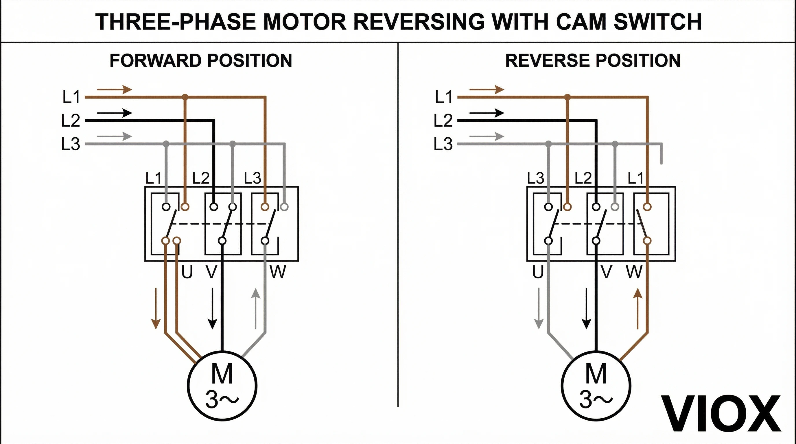
3. Αντιστροφή Τριφασικού Κινητήρα (Εμπρός-Off-Ανάστροφα)
Το πιο απαιτούμενο ηλεκτρολογικό σχέδιο. Ένας τριπολικός έκκεντρος διακόπτης αλλάζει δύο φάσεις κινητήρα για να αντιστρέψει την περιστροφή.
Συνδέσεις Ακροδεκτών:
Παροχή (κοινοί): L1 (Καφέ)→Κοινό 1, L2 (Μαύρο)→Κοινό 2, L3 (Γκρι)→Κοινό 3
- ΕΜΠΡΟΣ: U→L1, V→L2, W→L3
- OFF (ΕΚΤΟΣ ΛΕΙΤΟΥΡΓΙΑΣ): Όλα ανοιχτά
- ΑΝΑΠΟΔΑ: U→L3, V→L2, W→L1
Η αντιμετάθεση των L1 και L3 αντιστρέφει τον κινητήρα. Το L2 παραμένει στο V.
Εφαρμογές: Μεταφορείς, ανυψωτήρες, γερανοί, αναστρέψιμοι ανεμιστήρες.
Κρίσιμη Προειδοποίηση: Ποτέ μην αντιστρέφετε ενόσω λειτουργεί. Πάντα σταματήστε πρώτα στην κεντρική θέση OFF.
4. Αλλαγή Τροφοδοσίας Τριών Φάσεων (Μεταφορά Δικτύου/Γεννήτριας)
Ένας χειροκίνητος διακόπτης μεταφοράς για την επιλογή μεταξύ δύο πηγών τροφοδοσίας χωρίς κίνδυνο ανάδρασης.
Συνδέσεις Ακροδεκτών:
- Πηγή A (Δίκτυο): L1A, L2A, L3A → Κοινά 1A, 2A, 3A
- Πηγή B (Γεννήτρια): L1B, L2B, L3B → Κοινά 1B, 2B, 3B
- Φορτίο: T1, T2, T3 → Έξοδοι
Θέσεις: 1 (Δίκτυο), 0 (και οι δύο απομονωμένες), 2 (Γεννήτρια).
Εφαρμογές: Εφεδρική ισχύς, διπλές τροφοδοσίες κοινής ωφέλειας, μεταγωγή συντήρησης.
5. Επιλογέας Τριφασικού Βολτομέτρου/Αμπερομέτρου
Ένας έκκεντρος διακόπτης 4 θέσεων συνδέει ένα μετρητή σε κάθε φάση διαδοχικά.
Συνδέσεις Ακροδεκτών:
- Είσοδοι φάσης: L1, L2, L3 → Κοινά
- Είσοδος μετρητή → Τερματικό εξόδου
Θέσεις: 0 (OFF), 1 (L1-N), 2 (L2-N), 3 (L3-N).
Εφαρμογές: Πίνακες ελέγχου κινητήρα, πίνακες διανομής, παρακολούθηση γεννήτριας.
Σημείωση Αξιολόγησης: Η μεταγωγή βολτομέτρου χρειάζεται ελάχιστη ονομαστική τιμή ρεύματος. η μεταγωγή αμπερομέτρου πρέπει να ταιριάζει με το ρεύμα πλήρους φορτίου.
Διαδικασία εγκατάστασης βήμα προς βήμα
Ακολουθήστε αυτήν την ακολουθία για να καλωδιώσετε και να θέσετε σε λειτουργία σωστά έναν έκκεντρο διακόπτη.
1. Απενεργοποιήστε και Κλειδώστε το Κύκλωμα: Απενεργοποιήστε τον ανάντη αυτόματο διακόπτη. Εφαρμόστε την προσωπική σας συσκευή κλειδώματος και την προειδοποιητική ετικέτα. Ελέγξτε για τάση σε όλους τους αγωγούς πριν αγγίξετε οτιδήποτε.
2. Τοποθετήστε τον Έκκεντρο Διακόπτη: Βεβαιωθείτε ότι η εγκοπή του πίνακα ταιριάζει με τις διαστάσεις τοποθέτησης του διακόπτη (συνήθως 22mm, 30mm ή 40mm διάμετρος για περιστροφικούς έκκεντρους διακόπτες). Εγκαταστήστε τη φλάντζα, εάν παρέχεται. Εισαγάγετε τον διακόπτη από μπροστά, στερεώστε με το παξιμάδι τοποθέτησης από πίσω. Σφίξτε σταθερά, αλλά μην το σφίξετε υπερβολικά—θα ραγίσετε το περίβλημα.
3. Προετοιμάστε τα Καλώδια: Απογυμνώστε τα άκρα των καλωδίων στο μήκος που καθορίζεται από τον κατασκευαστή του διακόπτη (συνήθως 8-10mm). Εγκαταστήστε μονωτικούς ακροδέκτες σε όλα τα πολύκλωνα καλώδια—σφίξτε σταθερά με ένα κατάλληλο εργαλείο ακροδεκτών. Οι ακροδέκτες αποτρέπουν τη θραύση των κλώνων και εξασφαλίζουν αξιόπιστη επαφή.
4. Συνδέστε τα Καλώδια στους Ακροδέκτες: Ακολουθήστε το ηλεκτρολογικό σας διάγραμμα με ακρίβεια. Συνδέστε την εισερχόμενη τροφοδοσία σε κοινούς ακροδέκτες, τα εξερχόμενα καλώδια σε ακροδέκτες εξόδου. Εισαγάγετε πλήρως τα καλώδια στον ακροδέκτη, σφίξτε τις βίδες του ακροδέκτη χρησιμοποιώντας τη συγκεκριμένη ροπή: συνήθως 1,2-1,5 Nm για βίδες M3,5, 2,0-2,5 Nm για βίδες M4. Οι υπο-σφιγμένοι ακροδέκτες θερμαίνονται και αποτυγχάνουν. οι υπερ-σφιγμένες βίδες καταστρέφουν τα σπειρώματα.
5. Δρομολογήστε και Ασφαλίστε την Καλωδίωση: Δρομολογήστε τα καλώδια τακτοποιημένα μακριά από αιχμηρές άκρες και κινούμενα μέρη. Χρησιμοποιήστε δεματικά καλωδίων για να τακτοποιήσετε την καλωδίωση σε δέσμες. Διατηρήστε τον διαχωρισμό μεταξύ της καλωδίωσης τροφοδοσίας και της καλωδίωσης σήματος ελέγχου για να αποτρέψετε τον ηλεκτρικό θόρυβο.
6. Επισημάνετε τα Πάντα: Χρησιμοποιήστε μόνιμες ετικέτες για να επισημάνετε κάθε ακροδέκτη με την ονομασία του κυκλώματος. Επισημάνετε τις θέσεις της λαβής του διακόπτη (ΕΜΠΡΟΣ/OFF/ΑΝΑΠΟΔΑ ή 1/0/2, κ.λπ.). Οι μελλοντικοί τεχνικοί θα σας ευχαριστήσουν.
7. Επαληθεύστε με Έλεγχο Συνέχειας: Πριν επαναφέρετε την τροφοδοσία, χρησιμοποιήστε ένα πολύμετρο σε λειτουργία συνέχειας. Περιστρέψτε τη λαβή σε κάθε θέση και βεβαιωθείτε ότι οι σωστοί ακροδέκτες εμφανίζουν συνέχεια σε κάθε θέση. Αυτό εντοπίζει σφάλματα καλωδίωσης πριν ενεργοποιήσετε το κύκλωμα.
8. Κλείστε το Περίβλημα και Επαναφέρετε την Τροφοδοσία: Επανατοποθετήστε την πόρτα ή το κάλυμμα του πίνακα. Αφαιρέστε τη συσκευή κλειδώματος. Επαναφέρετε την τροφοδοσία στον αυτόματο διακόπτη.
9. Δοκιμάστε τη Λειτουργία: Πρώτα, δοκιμάστε χωρίς φορτίο (κινητήρας αποσυνδεδεμένος ή διακόπτης απενεργοποιημένος κατάντη). Βεβαιωθείτε ότι ο διακόπτης λειτουργεί ομαλά σε όλες τις θέσεις. Στη συνέχεια, δοκιμάστε υπό φορτίο. Για εφαρμογές κινητήρα, βεβαιωθείτε για την κατεύθυνση περιστροφής σε κάθε θέση πριν τρέξετε σε πλήρη ταχύτητα.
Αντιμετώπιση Συνήθων Προβλημάτων Καλωδίωσης
Ο Κινητήρας Τρέχει σε Λάθος Κατεύθυνση
- Αιτία: Δύο φάσεις είναι διασταυρωμένες.
- Διόρθωση: Απενεργοποιήστε. Αντιμεταθέστε οποιαδήποτε δύο από τα τρία καλώδια φάσης του κινητήρα (U και W, για παράδειγμα). Ελέγξτε ξανά.
Διακοπτόμενη Επαφή ή Δημιουργία Τόξου
- Αιτία: Χαλαρές συνδέσεις ακροδεκτών, φθαρμένες ή οξειδωμένες επαφές ή επαγωγικό φορτίο χωρίς καταστολή.
- Διόρθωση: Επανασφίξτε όλες τις βίδες των ακροδεκτών σύμφωνα με τις προδιαγραφές. Επιθεωρήστε τις επαφές για διάβρωση ή καύση. αντικαταστήστε το κιτ επαφών εάν έχει υποστεί ζημιά. Για επαγωγικά φορτία (κινητήρες, σωληνοειδή), προσθέστε ένα RC snubber (πυκνωτής 0,1µF και αντίσταση 100Ω σε σειρά) στις επαφές που αλλάζουν για να απορροφήσουν την ανάστροφη ΗΕΔ.
Ο Διακόπτης Κλείνει Όταν Λειτουργεί ο Διακόπτης
- Αιτία: Βραχυκύκλωμα από διασταυρωμένα καλώδια, κατεστραμμένη μόνωση ή ανεπαρκής απόσταση μεταξύ των φάσεων.
- Διόρθωση: Απενεργοποιήστε. Επιθεωρήστε όλη τη μόνωση των καλωδίων για ζημιά. Βεβαιωθείτε για την απομόνωση φάσης προς φάση και φάσης προς γείωση με ένα μεγγόμετρο (η αντίσταση μόνωσης πρέπει να είναι >1MΩ). Ελέγξτε ότι τα καλώδια δεν είναι τσιμπημένα κάτω από το υλικό τοποθέτησης.
Ο Διακόπτης Δεν Συμπεριφέρεται Όπως Αναμένεται (λάθος κυκλώματα αλλάζουν)
- Αιτία: Έχει επιλεγεί λάθος κωδικός προγράμματος έκκεντρου ή οι ακροδέκτες έχουν προσδιοριστεί εσφαλμένα κατά την καλωδίωση.
- Διόρθωση: Βεβαιωθείτε ότι ο κωδικός προγράμματος του διακόπτη ταιριάζει με την εφαρμογή σας. Συμβουλευτείτε το φύλλο δεδομένων του κατασκευαστή για τον πίνακα μεταγωγής. Εάν είναι απαραίτητο, χαρτογραφήστε την πραγματική συμπεριφορά μεταγωγής με έναν ελεγκτή συνέχειας και επανακαλωδιώστε για να ταιριάζει.
Συμπέρασμα & Βέλτιστες Πρακτικές
Η σωστή καλωδίωση ενός έκκεντρου διακόπτη συνοψίζεται σε τρία πράγματα: κατανόηση του τι κάνει κάθε ακροδέκτης, ακολουθώντας το σωστό διάγραμμα για την εφαρμογή σας και επαληθεύοντας κάθε σύνδεση πριν κλείσετε τον πίνακα. Τα επιπλέον πέντε λεπτά δοκιμής συνέχειας σε κάθε θέση αποτρέπουν την επανάκληση στις 2 π.μ. όταν κάτι πάει στραβά.
Βέλτιστες πρακτικές: χρησιμοποιείτε πάντα ακροδέκτες σε πολύκλωνο καλώδιο, εφαρμόστε τη σωστή ροπή ακροδεκτών, επισημάνετε κάθε σύνδεση. Τεκμηριώστε την εργασία σας με φωτογραφίες ή ένα επισημασμένο ηλεκτρολογικό διάγραμμα για τον φάκελο συντήρησης. Για εφαρμογές αντιστροφής κινητήρα, μην αλλάζετε ποτέ κατεύθυνση ενώ ο κινητήρας λειτουργεί—περάστε πάντα από τη θέση OFF.
Χρειάζεστε βοήθεια για την επιλογή του σωστού έκκεντρου διακόπτη για μια προσαρμοσμένη εφαρμογή ή έχετε ερωτήσεις σχετικά με τις διαμορφώσεις καλωδίωσης; Επικοινωνήστε με την ομάδα μηχανικών εφαρμογών της VIOX Electric. Παρέχουμε τεχνική υποστήριξη, προσαρμοσμένο προγραμματισμό έκκεντρου και γρήγορη παράδοση για κατασκευαστές πινάκων ελέγχου και κατασκευαστές OEM παγκοσμίως.
Σχετικοί Πόροι: