
Die Auswahl des richtigen Kabelquerschnitts für Ihren Schutzschalter dient nicht nur der Einhaltung von Vorschriften, sondern auch der Verhinderung von elektrischen Bränden, Geräteschäden und kostspieligen Ausfallzeiten. Die Beziehung zwischen Kabelgröße und Schalterstromstärke bildet die Grundlage für die elektrische Sicherheit in jeder Installation, von Wohnungsverteilern bis hin zu industriellen Schaltanlagen. Dieser Leitfaden bietet die maßgeblichen Dimensionierungstabellen, NEC-Konformitätsstrategien und Koordinationsprinzipien, die Elektroingenieure und Schaltschrankbauer für die Konstruktion sicherer und zuverlässiger Systeme benötigen.
Wichtigste Erkenntnisse
- Der Kabelquerschnitt muss immer der Nennleistung des Schutzschalters entsprechen oder diese übersteigen.– ein 20-A-Schutzschalter benötigt mindestens 12 AWG Kupferdraht, während ein 15-A-Schutzschalter mindestens 14 AWG benötigt.
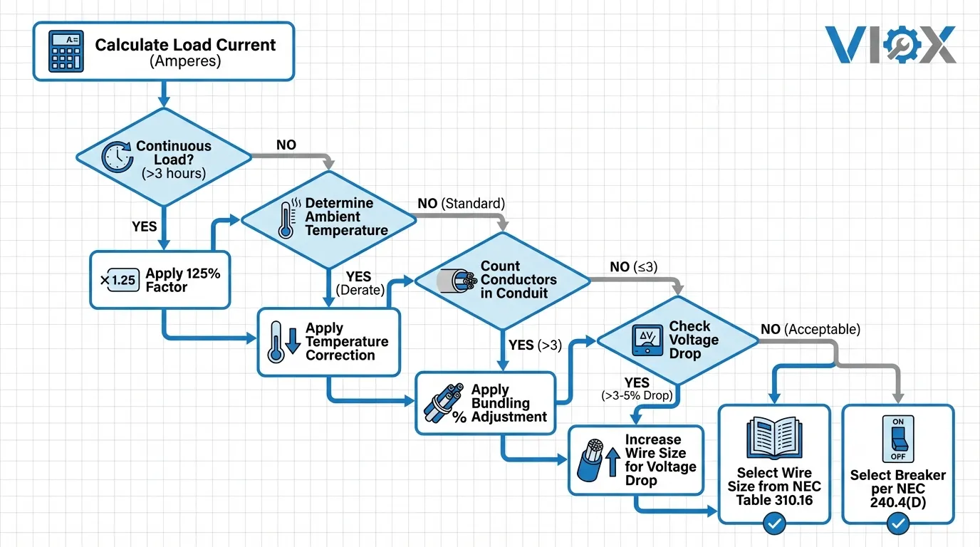
- Die 80%-Regel gilt für Dauerlasten: Schutzschalter auf 125% des Dauerstroms dimensionieren, um Fehlauslösungen und thermische Belastung zu vermeiden
- Temperatur- und Rohrfüllungs-Minderungsfaktoren können die Strombelastbarkeit des Kabels um 20-50% reduzieren, was größere Leiter erfordert, als Standardtabellen vermuten lassen
- NEC-Artikel 240.4(D) begrenzt den maximalen Überstromschutz für kleine Leiter: 15 A für 14 AWG, 20 A für 12 AWG und 30 A für 10 AWG Kupferdraht
- Selektive Koordination erfordert eine sorgfältige Dimensionierung der Schutzschalter– vorgelagerte Schutzschalter müssen deutlich höher bemessen sein als nachgelagerte Geräte, um Fehler zu isolieren, ohne kaskadierende Auslösungen zu verursachen
Grundlagen zum Verständnis von Kabelquerschnitt und Strombelastbarkeit
Der Kabelquerschnitt bezieht sich auf den physikalischen Durchmesser eines elektrischen Leiters, der im American Wire Gauge (AWG)-System für die meisten nordamerikanischen Anwendungen gemessen wird. Das AWG-System arbeitet umgekehrt – kleinere Zahlen bedeuten größere Kabeldurchmesser und eine höhere Strombelastbarkeit. Beispielsweise hat ein 10 AWG-Kabel einen größeren Durchmesser als ein 14 AWG-Kabel und kann sicher mehr Strom führen.
Die Strombelastbarkeit definiert den maximalen Dauerstrom, den ein Leiter führen kann, ohne seine Nenntemperatur zu überschreiten. Dieser kritische Parameter hängt von mehreren Faktoren ab: Leitermaterial (Kupfer vs. Aluminium), Isolationsart (THHN, THWN, XHHW), Installationsmethode (Rohr, Kabelrinne, freie Luft), Umgebungstemperatur und Anzahl der gebündelten stromführenden Leiter.
Die National Electrical Code (NEC) Tabelle 310.16 enthält grundlegende Strombelastbarkeitswerte für Kupfer- und Aluminiumleiter unter Standardbedingungen: drei oder weniger stromführende Leiter in einem Kabelkanal oder Kabel, Umgebungstemperatur von 30 °C (86 °F) und spezifische Isolationswerte. In der Realität entsprechen Installationen jedoch selten diesen idealen Bedingungen, sodass Ingenieure Korrektur- und Anpassungsfaktoren anwenden müssen, die die effektive Strombelastbarkeit reduzieren.
Das Verständnis dieser Grundlagen verhindert den gefährlichsten Fehler bei der Elektroplanung: die Installation eines Schutzschalters mit einer höheren Nennleistung als die Strombelastbarkeit des Kabels. Diese Konfiguration ermöglicht es dem Kabel, zu überhitzen und sich möglicherweise zu entzünden, bevor der Schalter auslöst, was eine ernsthafte Brandgefahr darstellt. Der Schutzschalter dient in erster Linie dem Schutz des Kabels, nicht der angeschlossenen Last.
Standardtabelle für Kabelquerschnitt und Schutzschalterstromstärke
Die folgende umfassende Tabelle zeigt die korrekte Paarung von Kabelquerschnitten mit Schutzschalternennwerten für Kupferleiter mit 75 °C-Isolierung (THHN/THWN), der gebräuchlichsten Spezifikation in kommerziellen und industriellen Anwendungen. Diese Werte entsprechen den NEC 2020-Anforderungen und setzen Standardinstallationsbedingungen voraus.
| Drahtgröße (AWG) | Strombelastbarkeit bei 75 °C | Maximale Schaltergröße | Typische Anwendungen | Berücksichtigung des Spannungsfalls |
|---|---|---|---|---|
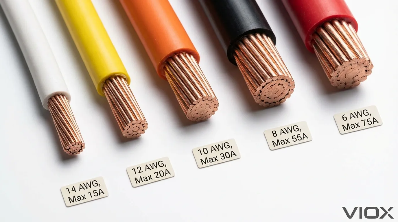
| 14 AWG | 20A | 15A | Beleuchtungskreise, Steckdosen | max. 15 m für 15 A |
| 12 AWG | 25A | 20A | Allgemeine Steckdosen, kleine Geräte | max. 18 m für 20 A |
| 10 AWG | 35A | 30A | Elektrische Warmwasserbereiter, große Geräte | max. 19,5 m für 30 A |
| 8 AWG | 50A | 40A | Elektroherde, große HLK-Anlagen | max. 24 m für 40 A |
| 6 AWG | 65A | 60A | Elektroöfen, Unterverteilungen | max. 30 m für 60 A |
| 4 AWG | 85A | 70A | Große kommerzielle Geräte | max. 40 m für 70 A |
| 3 AWG | 100A | 90A | Service entrance conductors | max. 45 m für 90 A |
| 2 AWG | 115A | 100A | Hauptverteilungen, große Motoren | max. 52 m für 100 A |
| 1 AWG | 130A | 110A | Industrielle Zuleitungen | max. 58 m für 110 A |
| 1/0 AWG | 150A | 125A | Hauseinführung, große Unterverteilungen | max. 65 m für 125 A |
| 2/0 AWG | 175A | 150A | Kommerzielle Hauseinführung | max. 73 m für 150 A |
| 3/0 AWG | 200A | 175A | Industrieller Vertrieb | max. 82 m für 175 A |
| 4/0 AWG | 230A | 200A | Hauptleitungen | max. 91 m für 200 A |
Wichtige Hinweise:
- Die maximalen Schutzschaltergrößen spiegeln die NEC 240.4(D)-Beschränkungen für Leiter mit 10 AWG und kleiner wider
- Spannungsfallbetrachtungen setzen 120-V-Einphasenkreise mit maximal 3% Spannungsfall voraus
- Für Aluminiumleiter erhöhen Sie die Kabelgröße um etwa zwei AWG-Größen für die gleiche Strombelastbarkeit
- Diese Werte gelten für Kupferleiter in Rohren bei einer Umgebungstemperatur von 30 °C
Diese Tabelle dient als primäre Referenz für die Zuordnung von Kabelquerschnitt und Schutzschalterstromstärke, überprüfen Sie jedoch immer die örtlichen Elektrovorschriften und die spezifischen Installationsbedingungen. Für Motorschutzanwendungen, gelten zusätzliche Überlegungen, die über die einfache Übereinstimmung der Strombelastbarkeit hinausgehen.
Die kritische 80%-Regel für Dauerlasten
Die NEC-80%-Regel stellt eine der am häufigsten missverstandenen Anforderungen bei der Dimensionierung von Schutzschaltern dar. Diese Regel, die in NEC 210.19(A) und 210.20(A) festgelegt ist, schreibt vor, dass Schutzschalter mit 125% der Dauerlasten dimensioniert werden müssen – oder umgekehrt, dass Dauerlasten 80% der Nennstromstärke des Schutzschalters nicht überschreiten dürfen.
Eine Dauerlast arbeitet drei Stunden oder länger ohne Unterbrechung. Häufige Beispiele sind HLK-Systeme, Kühlgeräte, Stromversorgungen für Rechenzentren und industrielle Prozessmaschinen. Die 80%-Regel existiert, weil Schutzschalter thermischer Belastung ausgesetzt sind, wenn sie über längere Zeiträume Strom in der Nähe ihrer Nennleistung führen, was möglicherweise zu vorzeitigem Ausfall oder Fehlauslösungen führt.
Praktisches Anwendungsbeispiel:
Betrachten Sie ein kommerzielles HLK-Gerät, das kontinuierlich 32 Ampere zieht. Viele Installateure gehen fälschlicherweise davon aus, dass ein 40-A-Schutzschalter ausreicht, da 32 A < 40 A. Bei Anwendung der 80%-Regel gilt jedoch:
- Dauerlast: 32A
- Erforderliche Leistung des Schutzschalters: 32A ÷ 0,80 = 40A Minimum
- Da 40A × 0,80 = 32A (genau am Limit), empfiehlt die bewährte Praxis die nächstgrößere Standardgröße
- Korrekte Größe des Schutzschalters: 45A oder 50A
- Erforderlicher Kabelquerschnitt: 8 AWG Kupfer Minimum (50A Strombelastbarkeit bei 75°C)
Dieser konservative Ansatz bietet thermische Reserve, reduziert die Belastung der Schutzschalterkomponenten und verhindert unerwünschte Auslösungen während des Anlaufens. Für elektrische Wartungsprogramme, reduzieren richtig dimensionierte Schutzschalter Serviceeinsätze und verlängern die Lebensdauer der Geräte.
Die 80%-Regel gilt nicht für Schutzschalter, die ausdrücklich als “100%-Nennstrom” gelistet sind und ihren vollen Nennstrom kontinuierlich führen können. Diese speziellen Schutzschalter sind jedoch deutlich teurer und erfordern spezielle Installationsbedingungen, wodurch sie in Standardanwendungen unüblich sind.
Temperatur- und Füllungsreduzierungsfaktoren für Kabelkanäle
Standard-Strombelastungstabellen gehen von idealen Bedingungen aus, die in realen Installationen selten gegeben sind. Zwei kritische Faktoren – Umgebungstemperatur und Leiterbündelung – können die sichere Strombelastbarkeit eines Kabels drastisch reduzieren, manchmal um 50% oder mehr. Die Nichtberücksichtigung dieser Reduzierungsfaktoren stellt eine häufige, aber gefährliche Nachlässigkeit bei der elektrischen Planung dar.
Temperaturkorrekturfaktoren
NEC-Tabelle 310.15(B)(2)(a) enthält Temperaturkorrekturfaktoren, wenn die Umgebungstemperatur die Standardbasislinie von 30°C (86°F) überschreitet. Hochtemperaturumgebungen reduzieren die Strombelastbarkeit erheblich, da das Kabel weniger thermische Reserve hat, bevor es seine Isolierungstemperaturgrenze erreicht.
| Temperatur in der Umgebung | Korrekturfaktor (75°C Isolierung) | Korrekturfaktor (90°C Isolierung) |
|---|---|---|
| 30 °C (86 °F) | 1.00 | 1.00 |
| 40°C (104°F) | 0.88 | 0.91 |
| 50°C (122°F) | 0.75 | 0.82 |
| 60°C (140°F) | 0.58 | 0.71 |
| 70°C (158°F) | — | 0.58 |
Beispiel: Ein 10 AWG Kupferleiter mit einer Nennleistung von 35A bei 75°C in einer 50°C Umgebung hat eine angepasste Strombelastbarkeit von 35A × 0,75 = 26,25A. Dies erfordert eine Vergrößerung auf 8 AWG (50A × 0,75 = 37,5A), um eine ausreichende Kapazität zu erhalten.
Anpassungsfaktoren für die Kabelkanalfüllung
Wenn mehr als drei stromführende Leiter denselben Kabelkanal oder dasselbe Kabel belegen, reduziert die gegenseitige Erwärmung die Strombelastbarkeit jedes Leiters. NEC-Tabelle 310.15(B)(3)(a) gibt Anpassungsfaktoren basierend auf der Anzahl der Leiter an.
| Anzahl der Leiter | Anpassungsfaktor |
|---|---|
| 1-3 | 1.00 |
| 4-6 | 0.80 |
| 7-9 | 0.70 |
| 10-20 | 0.50 |
| 21-30 | 0.45 |
| 31-40 | 0.40 |
Kombiniertes Reduzierungsbeispiel:
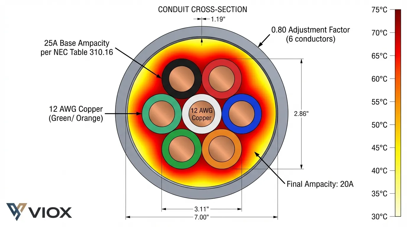
Eine industrielle Schaltschrankinstallation erfordert sechs 12 AWG Leiter in einem einzigen Kabelkanal, der sich in einer 45°C Umgebung befindet:
- Basisstrombelastbarkeit (12 AWG, 75°C): 25A
- Temperaturkorrektur (45°C): 0,82
- Kabelkanalfüllungsanpassung (6 Leiter): 0,80
- Angepasste Strombelastbarkeit: 25A × 0,82 × 0,80 = 16,4A
- Standard 12 AWG Kabel, normalerweise ausreichend für 20A Schutzschalter, unterstützt jetzt nur noch maximal 15A
Dieses Beispiel zeigt, warum Industrierschaltschrankdesign sorgfältige Strombelastungsberechnungen über einfache Tabellennachschläge hinaus erforderlich sind. Für Schaltanlagenanwendungen, verhindert die richtige Reduzierung Überhitzung und verlängert die Lebensdauer der Geräte.
NEC-Artikel 240.4(D): Schutzgrenzen für kleine Leiter
NEC-Artikel 240.4(D) legt absolute maximale Überstromschutzgrenzen für kleine Leiter fest, unabhängig von ihren Strombelastbarkeitswerten aus Tabelle 310.16. Diese kritische Sicherheitsbestimmung verhindert, dass Installateure Schutzschalter auf kleinen Kabelquerschnitten überdimensionieren, selbst wenn Reduzierungsfaktoren dies ansonsten zulassen würden.
Die Regel legt diese maximalen Schutzschaltergrößen für Kupferleiter fest:
- 14 AWG: maximal 15A (obwohl 14 AWG eine Strombelastbarkeit von 20A bei 75°C hat)
- 12 AWG: maximal 20A (obwohl 12 AWG eine Strombelastbarkeit von 25A bei 75°C hat)
- 10 AWG: maximal 30A (obwohl 10 AWG eine Strombelastbarkeit von 35A bei 75°C hat)
Diese Einschränkungen bestehen, weil kleine Leiter eine begrenzte thermische Masse haben und sich unter Fehlerbedingungen schnell überhitzen können, noch bevor sie ihre stationären Strombelastungsgrenzen erreichen. Die Regel schafft eine zusätzliche Sicherheitsmarge für die am häufigsten verwendeten Kabelquerschnitte in Wohn- und leichten Gewerbeanwendungen.
Kritische Implikation: Sie können einen Schutzschalter auf kleinen Leitern nicht “vergrößern”, um Reduzierungsfaktoren auszugleichen. Wenn die Strombelastbarkeit eines 12 AWG Leiters aufgrund von Temperatur- oder Bündelungsreduzierung unter 20A fällt, müssen Sie entweder:
- Die Stromkreislast reduzieren, um innerhalb der reduzierten Strombelastbarkeit zu bleiben
- Das Kabel auf 10 AWG oder größer vergrößern
- Die Installationsbedingungen ändern, um die Reduzierungsanforderungen zu verringern
Diese Regel wirkt sich häufig aus Auswahl von Leistungsschaltern in dicht gepackten Schalttafeln und Hochtemperaturumgebungen. Für MCCB-Anwendungen, verhindert das Verständnis dieser Grenzen Spezifikationsfehler, die die Sicherheit beeinträchtigen.
Selektive Koordination und Strategie zur Schutzschalterdimensionierung
Die selektive Koordination stellt sicher, dass nur der dem Fehler am nächsten liegende Schutzschalter auslöst, während alle vorgeschalteten Schutzschalter geschlossen bleiben und die Stromversorgung zu nicht betroffenen Stromkreisen aufrechterhalten wird. Dieses kritische Designprinzip minimiert Ausfallzeiten in gewerblichen und industriellen Anlagen, insbesondere in Anwendungen, in denen NEC eine Koordination erfordert: Notstromsysteme (NEC 700.28), gesetzlich vorgeschriebene Standby-Systeme (NEC 701.27) und kritische Stromversorgungssysteme (COPS).
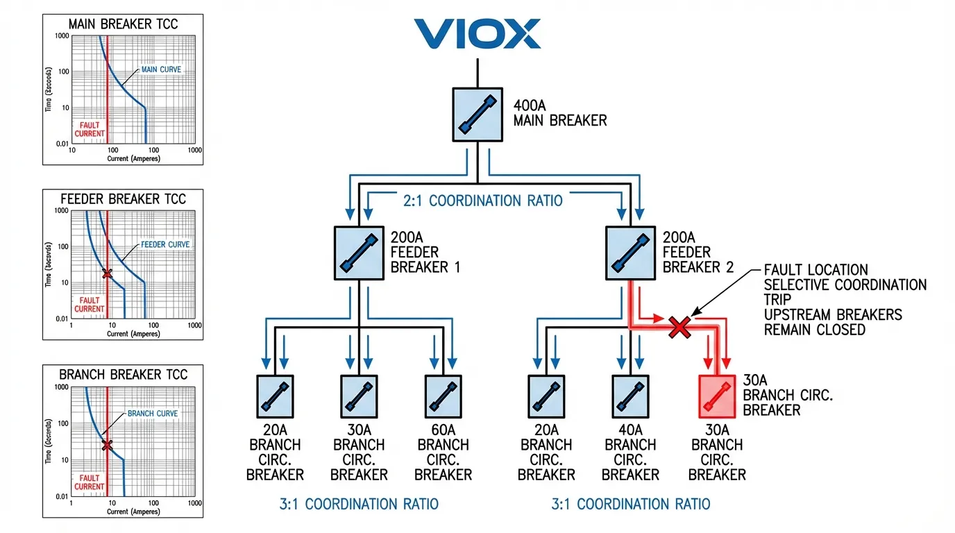
Das Erreichen einer selektiven Koordination erfordert sorgfältige Beachtung der Beziehung zwischen den Nennwerten der vor- und nachgeschalteten Schutzschalter, den Zeit-Strom-Kennlinien und den verfügbaren Kurzschlussstrompegeln. Das grundlegende Prinzip: Vorgeschaltete Schutzschalter müssen deutlich höher bemessen sein als nachgeschaltete Geräte und langsamere Auslösecharakteristiken aufweisen.
Richtlinien für das Koordinationsverhältnis
Während die spezifischen Koordinationsanforderungen von einer detaillierten Zeit-Strom-Kurvenanalyse abhängen, bieten allgemeine Dimensionierungsverhältnisse einen Ausgangspunkt:
- Mindestverhältnis von 2:1 für thermisch-magnetische Schutzschalter: Ein 100A Hauptschutzschalter kann mit 50A Abzweigschutzschaltern koordiniert werden
- Ein Verhältnis von 1,5:1 kann mit elektronischen Auslöseschutzschaltern funktionieren: Fortschrittliche Auslöseeinheiten bieten eine bessere Unterscheidung
- Höhere Verhältnisse bei hohen Fehlerströmen erforderlich: Die Kurzschlusskoordination ist anspruchsvoller als die Überlastkoordination
Praktisches Koordinationsbeispiel:
Ein elektrisches Systemdesign für ein Gewerbegebäude:
- Serviceeingang: 400A Hauptschutzschalter
- Unterverteiler: 200A-Leistungsschalter (Verhältnis 2:1 beibehalten)
- Branch circuits: 20-60A-Leistungsschalter (Verhältnisse 3:1 bis 10:1)
Dieser gestaffelte Ansatz stellt sicher, dass ein Fehler in einem 20A-Beleuchtungskreis nur diesen Abzweigleistungsschalter auslöst, nicht aber den 200A-Zuleiter oder den 400A-Hauptschalter. Die Stromversorgung aller anderen Gebäudesysteme bleibt erhalten.
Koordinationsherausforderungen bei kleinen Leistungsschaltern
Die Koordination wird mit kleineren Leistungsschaltergrößen zunehmend schwieriger, da die verfügbaren Nennstromstufen abnehmen. Ein 15A- bis 20A-Abzweigstromkreis bietet nur ein Verhältnis von 1,33:1, was eine echte Koordination mit Standard-Thermo-Magnet-Leistungsschaltern nahezu unmöglich macht. Diese Einschränkung erklärt, warum viele Wohn- und leichte Gewerbeinstallationen keine vollständige selektive Koordination erreichen können.
Für Lichtbogenfehlerschutz und Erdschlussschutz Anwendungen erfordert die Koordination zusätzliche Berücksichtigung spezieller Auslösefunktionen, die über den einfachen Überstromschutz hinausgehen. Moderne elektronische Auslöseeinheiten bieten programmierbare Zeitverzögerungen, die die Koordinationsmöglichkeiten verbessern.
Häufige Fehler bei der Drahtdimensionierung und wie man sie vermeidet
Selbst erfahrenen Elektrikern und Ingenieuren unterlaufen Fehler bei der Drahtdimensionierung, die die Sicherheit und die Einhaltung von Vorschriften beeinträchtigen. Das Verständnis dieser häufigen Fehler hilft Ihnen, kostspielige Nacharbeiten und potenzielle Gefahren zu vermeiden.
Fehler #1: Spannungsabfall ignorieren
Viele Installateure konzentrieren sich ausschließlich auf die Strombelastbarkeit und vernachlässigen dabei den Spannungsabfall, insbesondere bei langen Stromkreisstrecken. Der NEC empfiehlt, den Spannungsabfall auf 3 % für Abzweigstromkreise und insgesamt 5 % für Zuleiter plus Abzweigstromkreise zu begrenzen. Ein übermäßiger Spannungsabfall verursacht Fehlfunktionen der Geräte, einen geringeren Wirkungsgrad und eine verkürzte Lebensdauer des Motors.
Lösung: Berechnen Sie bei Stromkreisen, die länger als 50 Fuß sind, den Spannungsabfall mit der folgenden Formel:
VD = 2 × K × I × L / CM
Wo:
- VD = Spannungsabfall (Volt)
- K = Widerstandskonstante (12,9 für Kupfer, 21,2 für Aluminium)
- I = Strom (Ampere)
- L = einfache Stromkreislänge (Fuß)
- CM = Circular Mils (Drahtquerschnittsfläche)
Vergrößern Sie die Leiter, wenn der berechnete Spannungsabfall 3 % der Systemspannung überschreitet. Für Richtlinien zur Kabeldimensionierung, beziehen Sie sich auf die Normen IEC 60204-1.
Fehler #2: Verwendung der Leistungsschaltergröße als Drahtgrößenindikator
Eine häufige, aber gefährliche Annahme: “Ich habe einen 30A-Leistungsschalter, also brauche ich 10 AWG-Draht.” Diese Logik versagt, wenn Derating-Faktoren gelten oder wenn der Leistungsschalter mehrere Stromkreise mit unterschiedlichen Drahtgrößen schützt.
Lösung: Berechnen Sie die erforderliche Strombelastbarkeit immer auf der Grundlage der tatsächlichen Last, wenden Sie alle relevanten Derating-Faktoren an und wählen Sie dann die Drahtgröße aus den Strombelastbarkeitstabellen aus. Erst nach der Bestimmung der Drahtgröße sollten Sie den entsprechenden Leistungsschalternennwert auswählen.
Fehler #3: Mischen von Kupfer und Aluminium ohne Anpassung
Aluminiumleiter benötigen für eine äquivalente Strombelastbarkeit etwa zwei AWG-Größen mehr als Kupfer. Die Installation von Aluminiumdraht, der für Kupferstrombelastbarkeitswerte dimensioniert ist, stellt eine ernsthafte Brandgefahr dar.
Lösung: Verwenden Sie bei der Verwendung von Aluminiumleitern die Aluminiumspalten in NEC-Tabelle 310.16 und stellen Sie sicher, dass alle Anschlüsse für Aluminiumleiter ausgelegt sind (AL- oder AL/CU-Kennzeichnung). Für Sammelschienenanwendungen, beeinflusst die Materialauswahl die Leistung erheblich.
Fehler #4: Übersehen der Klemmentemperaturbewertungen
Selbst wenn die Drahtstrombelastbarkeit den Leistungsschalternennwert übersteigt, können Klemmentemperaturbegrenzungen eine Reduzierung der Nennleistung erforderlich machen. NEC 110.14(C) schreibt vor, dass Leiter basierend auf der niedrigeren der Leiter- oder Klemmentemperaturbewertung dimensioniert werden müssen.
Lösung: Verwenden Sie für Geräte mit einer Nennleistung von 100 A oder weniger die 60 °C-Strombelastbarkeitsspalte, es sei denn, die Geräte sind speziell für 75 °C-Anschlüsse gekennzeichnet. Verwenden Sie für Geräte mit einer Nennleistung über 100 A die 75 °C-Spalte, sofern nicht anders gekennzeichnet. Dies erfordert oft einen größeren Draht, als Strombelastbarkeitsberechnungen allein vermuten lassen würden.
Für Rahmen für den Stromkreisschutz Die systematische Behebung dieser häufigen Fehler bei der Entwicklung gewährleistet zuverlässige, normenkonforme Installationen.
Sonderanwendungen: Motoren, HLK und Dauerlasten
Bestimmte elektrische Lasten erfordern modifizierte Ansätze zur Drahtdimensionierung, die über die Standardberechnungen für Abzweigstromkreise hinausgehen. Das Verständnis dieser Sonderfälle verhindert Unterdimensionierung und Verstöße gegen Vorschriften.
Dimensionierung von Motorschaltungen
Motorschaltungen stellen besondere Herausforderungen dar, da der Anlaufstrom 600-800 % des Volllaststroms erreichen kann. NEC-Artikel 430 legt spezifische Anforderungen fest:
- Leiter: Dimensionierung mit 125 % des Motorvolllaststroms (FLA) aus NEC-Tabelle 430.250
- Abzweigstromkreis-Leistungsschalter: Dimensionierung mit 250 % des FLA für inverszeitverzögerte Leistungsschalter (NEC 430.52)
- Überlastungsschutz: Separates Überlastrelais, dimensioniert auf 115-125 % des FLA
Beispiel: Ein 10-PS-, 230-V-, 3-Phasen-Motor mit 28 A FLA:
- Leiterdimensionierung: 28 A × 1,25 = 35 A → erfordert mindestens 8 AWG Kupfer
- Abzweigstromkreis-Leistungsschalter: 28 A × 2,5 = 70 A → Verwendung eines 70A- oder 80A-Leistungsschalters
- Überlastrelais: 28 A × 1,15 = 32,2 A Einstellung
Dieser Ansatz ermöglicht es, dass der hohe Anlaufstrom fließt, ohne dass es zu Fehlauslösungen kommt, und bietet gleichzeitig einen angemessenen Überlastschutz während des Betriebs. Umfassende Anleitungen finden Sie in unserem Auswahlleitfaden für Motorstarter und Vergleich von thermischen Überlastrelais.
HVAC-Ausrüstung
Klimaanlagen und Wärmepumpenanlagen erfordern aufgrund des Blockierstroms, der Anlaufeigenschaften des Kompressors und des Dauerbetriebs besondere Berücksichtigung. Die Typenschilder der Geräte geben Folgendes an:
- Minimale Stromkreisbelastbarkeit (MCA): Bestimmt die erforderliche Drahtgröße
- Maximaler Überstromschutz (MOP): Bestimmt die maximale Leistungsschaltergröße
Verwenden Sie immer diese Typenschildwerte, anstatt sie nur aus dem Betriebsstrom zu berechnen. Der Hersteller hat bereits den Anlaufstrom, mehrere Motoren und den Dauerbetrieb berücksichtigt.
Ladestationen für Elektrofahrzeuge
EV-Ladegeräte stellen Dauerlasten dar, die die Anwendung eines Dimensionierungsfaktors von 125 % erfordern. Darüber hinaus stellt NEC-Artikel 625 spezifische Anforderungen:
- Level-2-Ladegeräte (240 V, 40 A): Benötigen einen 50A-Leistungsschalter und mindestens 6 AWG Kupfer
- Mehrere Ladegeräte: Lastmanagementsysteme können die Dimensionierungsanforderungen reduzieren
- FI-Schutzschalter: Erforderlich für alle EV-Versorgungsgeräte
Detaillierte Anleitungen finden Sie in unserem Leitfaden zur Dimensionierung von Leistungsschaltern für EV-Ladegeräte und Gewerblicher EV-Ladeschutz.
Internationale Normen: IEC- vs. NEC-Ansätze
Obwohl sich dieser Leitfaden hauptsächlich auf die in Nordamerika üblichen NEC-Anforderungen konzentriert, arbeiten viele VIOX-Kunden international mit IEC-Normen. Das Verständnis der wichtigsten Unterschiede verhindert Fehler in globalen Projekten.
Unterschiede bei der Drahtstärke
- Messsystem: IEC verwendet die Querschnittsfläche in mm² anstelle von AWG
- Strombelastungstabellen: IEC 60364-5-52 liefert andere Strombelastungswerte als NEC Tabelle 310.16
- Installationsmethoden: IEC definiert mehr Installationsmethodenkategorien, die die Strombelastbarkeit beeinflussen
Übliche Umrechnungen:
- 14 AWG ≈ 2,5 mm²
- 12 AWG ≈ 4 mm²
- 10 AWG ≈ 6 mm²
- 8 AWG ≈ 10 mm²
Ansätze zur Schutzschalterkoordination
IEC 60947-2 definiert andere Schutzschaltereigenschaften und Koordinationsanforderungen als die NEC/UL-Normen. IEC-Schutzschalter verwenden andere Auslösekennlinienbezeichnungen (B-, C-, D-Kurven) als in Nordamerika üblich. Für Projekte, die beide Normen erfordern, siehe unseren NEC- vs. IEC-Terminologieleitfaden.
Häufig Gestellte Fragen
F: Kann ich einen 20A-Schutzschalter für einen 14 AWG-Draht verwenden?
Nein. NEC 240.4(D) begrenzt den 14 AWG-Kupferdraht auf maximal 15 A Überstromschutz, obwohl seine Strombelastbarkeit bei 75 °C 20 A beträgt. Diese Regel dient dazu, eine zusätzliche Sicherheitsmarge für die kleinste üblicherweise verwendete Leitergröße zu gewährleisten. Verwenden Sie immer einen 15A-Schutzschalter mit 14 AWG-Draht.
F: Was passiert, wenn ich einen größeren Schutzschalter installiere, als der Draht vertragen kann?
Die Installation eines überdimensionierten Schutzschalters stellt eine ernsthafte Brandgefahr dar. Der Draht überhitzt und entzündet möglicherweise die Isolierung oder die umliegenden Materialien, bevor der Schutzschalter auslöst. Die Hauptfunktion des Schutzschalters besteht darin, den Draht zu schützen, nicht die angeschlossene Last. Überschreiten Sie niemals die Strombelastbarkeit des Drahtes bei der Auswahl der Schutzschaltergröße.
F: Wie berücksichtige ich den Spannungsabfall bei langen Drahtstrecken?
Berechnen Sie den Spannungsabfall mit der Formel VD = 2 × K × I × L / CM, wobei K = 12,9 für Kupfer. Wenn der berechnete Spannungsabfall 3 % der Systemspannung überschreitet, vergrößern Sie den Leiter auf die nächstgrößere Stärke und berechnen Sie ihn neu. Bei 120V-Stromkreisen entsprechen 3 % einem maximalen Abfall von 3,6V. Lange Strecken erfordern oft Drahtstärken, die deutlich größer sind, als die Strombelastbarkeit allein vermuten lässt.
F: Muss ich die Strombelastbarkeit des Drahtes für jede Installation reduzieren?
Eine Reduzierung ist immer dann erforderlich, wenn die tatsächlichen Installationsbedingungen von den Standardannahmen in NEC Tabelle 310.16 abweichen: drei oder weniger stromführende Leiter, 30 °C Umgebungstemperatur und spezifizierte Isolationsarten. Die meisten realen Installationen erfordern mindestens eine Temperaturkorrektur oder eine Anpassung der Rohrfüllung. Bewerten Sie immer, ob Reduktionsfaktoren für Ihre spezifische Installation gelten.
F: Kann ich Aluminiumdraht anstelle von Kupfer verwenden, um Kosten zu sparen?
Aluminiumdraht ist für viele Anwendungen akzeptabel, erfordert aber etwa zwei AWG-Größen größer als Kupfer für die gleiche Strombelastbarkeit. Alle Anschlüsse müssen für Aluminium ausgelegt sein (gekennzeichnet mit AL oder AL/CU), und es muss eine geeignete Antioxydationsverbindung aufgetragen werden. Aluminium ist am kostengünstigsten für große Leiter (4 AWG und größer), wo die Materialkosteneinsparungen die größere Größenanforderung überwiegen.
F: Was ist der Unterschied zwischen 80 %- und 100 %-Schutzschaltern?
Standard-Leistungsschalter sind für 80 % ausgelegt, was bedeutet, dass Dauerlasten nicht mehr als 80 % der Nennleistung des Leistungsschalters betragen dürfen. Leistungsschalter, die speziell als 100 % ausgelegt sind, können ihren vollen Nennstrom kontinuierlich führen, erfordern jedoch spezifische Installationsbedingungen (typischerweise in geeigneten Gehäusen eingeschlossen) und kosten deutlich mehr. Die meisten Anwendungen verwenden Standard-Leistungsschalter mit 80 % Nennleistung und entsprechenden Dimensionierungsfaktoren.
Fazit: Aufbau sichererer elektrischer Systeme durch richtige Koordination
Die richtige Drahtstärke und Schutzschalterkoordination bilden die Grundlage für die elektrische Sicherheit in jeder Installation. Durch das Verständnis der Grundlagen der Strombelastbarkeit, die Anwendung der NEC-Anforderungen, einschließlich der 80 %-Regel und der Einschränkungen gemäß Artikel 240.4(D), die Berücksichtigung von Reduktionsfaktoren und die Implementierung selektiver Koordinationsstrategien können Sie elektrische Systeme entwerfen, die sowohl Menschen als auch Geräte schützen und gleichzeitig Ausfallzeiten minimieren.
Die Beziehung zwischen Drahtstärke und Schutzschalterstromstärke ist nicht willkürlich – sie repräsentiert Jahrzehnte an elektrotechnischem Wissen und Sicherheitsdaten, die im National Electrical Code kodifiziert sind. Jede Drahtstärkenauswahl und Schutzschalterdimensionierungsentscheidung verbessert oder beeinträchtigt die Sicherheit Ihrer elektrischen Installation.
Für die B2B-Beschaffung von elektrischen Geräten fertigt VIOX Electric eine komplette Palette von Leistungsschalter, MCBs, MCCBsund Verteilungsanlagen die sowohl die NEC- als auch die IEC-Normen erfüllen. Unser technisches Team bietet Anwendungsunterstützung, um die richtige Drahtstärke und Schutzschalterkoordination für Ihre spezifischen Anforderungen sicherzustellen.
