
Wichtigste Erkenntnisse
- Standarddistanz: 12/2-Draht an einem 20-Ampere-Schutzschalter kann sicher 15-18 Meter (50-60 Fuß) bei Volllast betrieben werden, während der von NEC empfohlene Spannungsabfall von 3 % eingehalten wird
- Maximale sichere Distanz: Bis zu 28 Meter (93 Fuß) sind bei einem Spannungsabfall von 3 % bei 240 V möglich, aber nur 15-17 Meter (50-57 Fuß) bei 120 V
- Last ist entscheidend: Die tatsächlich nutzbare Distanz hängt stark von der angeschlossenen Last ab – eine geringere Stromstärke ermöglicht längere Leitungswege
- Sicherheitshinweis: Jenseits der empfohlenen Distanzen erhöht sich die Fehlerschleifenimpedanz, wodurch möglicherweise das Auslösen von Schutzschaltern bei Kurzschlüssen verhindert wird
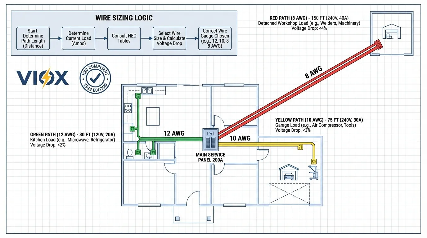
- Upgrade-Regel: Für Leitungswege über 18 Meter (60 Fuß) bei 20 Ampere auf 10 AWG aufrüsten; für über 30 Meter (100 Fuß) 8 AWG-Draht in Betracht ziehen
Die zwei Grenzwerte verstehen: Strombelastbarkeit vs. Spannungsabfall
Wenn Elektriker und Ingenieure darüber diskutieren, wie weit man 12/2-Draht an einem 20-Ampere-Schutzschalter verlegen kann, sprechen sie eigentlich zwei völlig unterschiedliche Einschränkungen an:
Die thermische Grenze (Strombelastbarkeit)
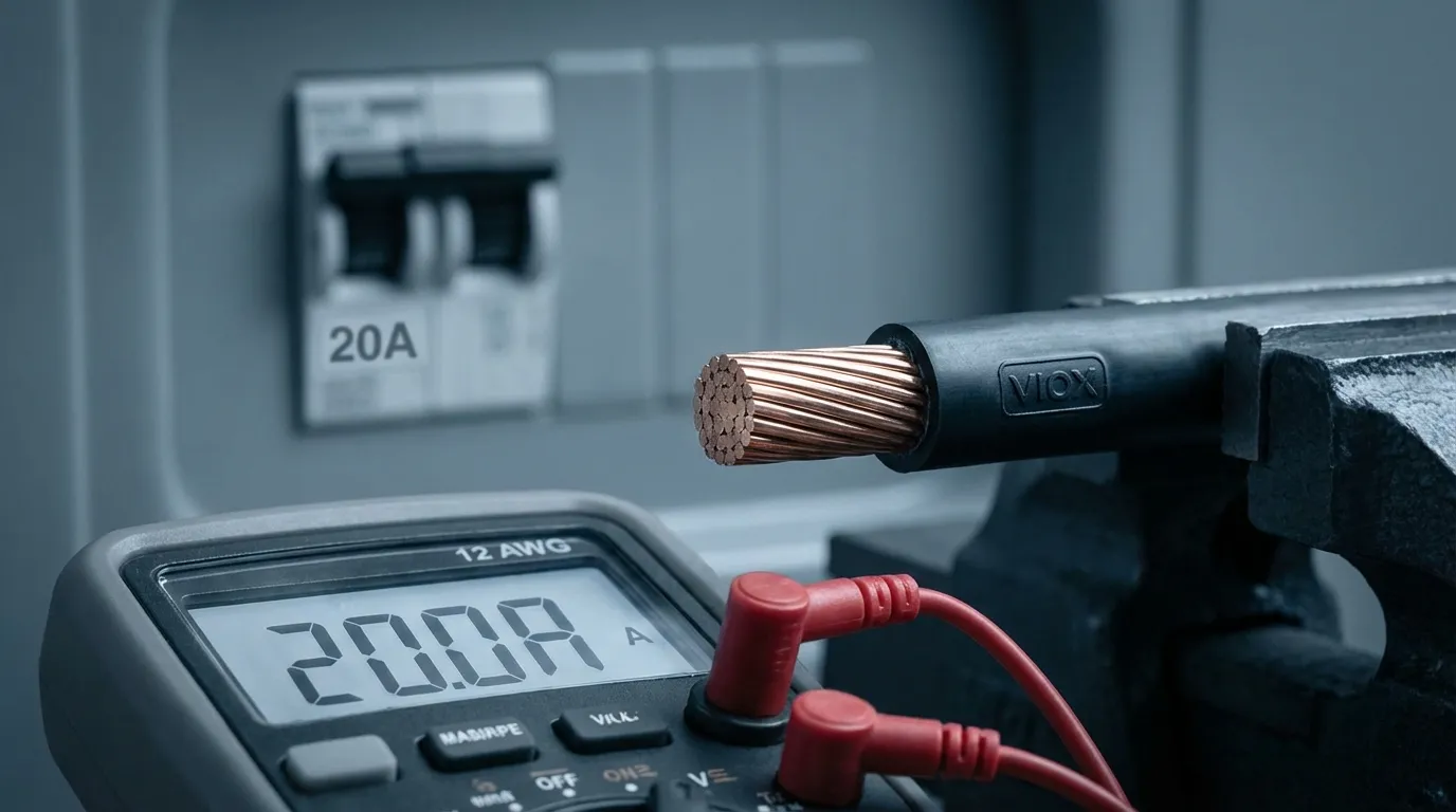
Gemäß NEC-Tabelle 310.16 ist, 12 AWG-Kupferdraht für 20 Ampere ausgelegt bei 60 °C und 25 Ampere bei 90 °C (für THHN/THWN-2-Isolierung). Diese Nennleistung stellt sicher, dass der Draht nicht überhitzt und seine Isolierung schmilzt – unabhängig von der Länge.
Die Leistungsgrenze (Spannungsabfall)
Spannungsabfall ist der stille Killer der elektrischen Leistung. Wenn Strom durch einen Draht fließt, führt der Widerstand zu einem Spannungsabfall. Der NEC empfiehlt, den Spannungsabfall auf Folgendes zu begrenzen:
- 3 % Maximum für Stromkreise (NEC 210.19(A)(1) FPN Nr. 4)
- 5 % Maximum kombiniert für Zuleitungen und Stromkreise
- 2 % Maximum für empfindliche elektronische Geräte (NEC 647.4(D))
Diese Spannungsabfallgrenze – nicht die Strombelastbarkeit – bestimmt die praktische maximale Distanz für 12/2-Draht.
Die Mathematik hinter der maximalen Drahtdistanz
Formel zur Berechnung des Spannungsabfalls
Die grundlegende Formel zur Berechnung des Spannungsabfalls in einem Zwei-Draht-Kreis ist:
VD = (2 × R × I × L) / 1000
Wo:
- VD = Spannungsabfall (Volt)
- R = Widerstand pro 300 Meter (1.000 Fuß) (Ohm)
- I = Stromstärke (Ampere)
- L = Einwegdistanz (Fuß)
- 2 = Berücksichtigt sowohl heiße als auch neutrale Leiter
Für 12 AWG-Kupferdraht: R = 1,93 Ohm pro 300 Meter (1.000 Fuß) (NEC Kapitel 9, Tabelle 8)
Formel für die maximale Distanz
Umstellen der Formel zur Berechnung der maximalen Distanz:
Maximale Distanz (Fuß) = (Maximaler VD × 1000) / (2 × R × I)
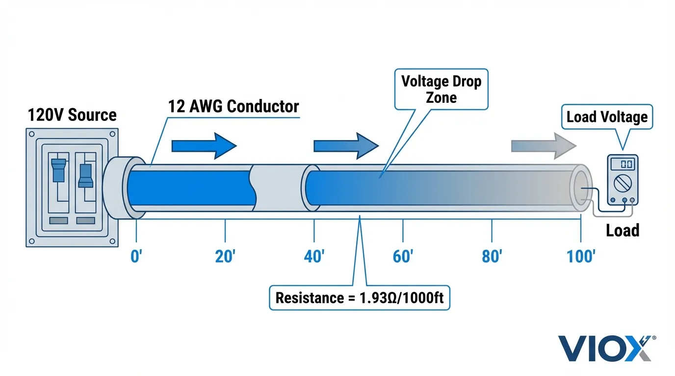
Tabelle der maximalen Distanz: 12/2-Draht an einem 20-Ampere-Schutzschalter
| System Spannung | Laststrom | Maximale Distanz (3 % VD) | Maximale Distanz (5 % VD) | Tatsächliche Spannung an der Last (3 %) |
|---|---|---|---|---|
| 120V | 20A (100 %) | 15,5 Meter (51 Fuß) | 26 Meter (85 Fuß) | 116,4V |
| 120V | 16A (80 %) | 19,5 Meter (64 Fuß) | 32 Meter (106 Fuß) | 116,4V |
| 120V | 12A (60 %) | 26 Meter (85 Fuß) | 43 Meter (142 Fuß) | 116,4V |
| 120V | 8A (40 %) | 39 Meter (128 Fuß) | 213 Fuß | 116,4V |
| 240V | 20A (100 %) | 28 Meter (93 Fuß) | 155 Fuß | 232,8 V |
| 240V | 16A (80 %) | 116 Fuß | 194 Fuß | 232,8 V |
Hinweis: Entfernungen sind einfache Messungen vom Panel zur Last
Warum die 80%-Regel wichtig ist
Der NEC schreibt vor, dass Dauerlasten (Betrieb für 3+ Stunden) berechnet werden müssen mit 125% der tatsächlichen Last, was bedeutet, dass ein 20-Ampere-Stromkreis nur 16 Ampere dauerhaft führen sollte (80% der Nennkapazität). Dies bietet eine Sicherheitsmarge und erweitert die praktisch maximale Entfernung.
Reale Distanzszenarien
Szenario 1: Werkstatt im Freien (Volle 20A Last)
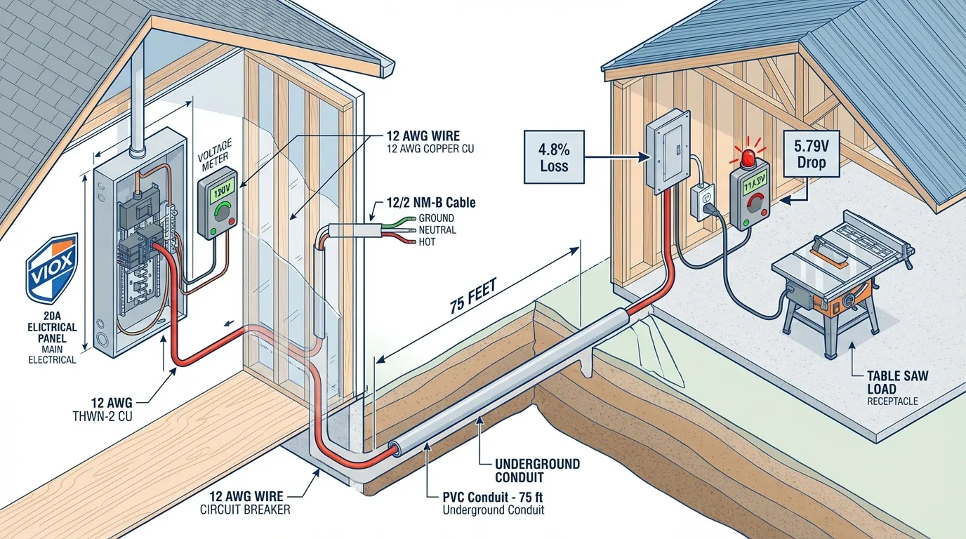
Einrichtung: Verlegung von 12/2-Draht vom Hauptpanel zur Werkstatt im Freien mit Elektrowerkzeugen (Tischkreissäge, Luftkompressor), die 18-20 Ampere ziehen.
Distanz: 75 Fuß
Berechnung:
- VD = (2 × 1,93 × 20 × 75) / 1000 = 5,79 Volt
- Spannungsabfall in Prozent = 5,79 V / 120 V = 4.8%
Ergebnis: ❌ Überschreitet die 3%-Empfehlung (liegt aber innerhalb des maximalen 5%-Werts)
Empfehlung: Upgrade auf 10 AWG Draht um den Spannungsabfall auf 2,9% (3,6 V) zu reduzieren
Szenario 2: Landschaftsbeleuchtung (Geringe Stromstärke)
Einrichtung: LED-Landschaftsbeleuchtung, die nur 3 Ampere zieht, 150 Fuß vom Panel entfernt.
Berechnung:
- VD = (2 × 1,93 × 3 × 150) / 1000 = 1,74 Volt
- Spannungsabfall in Prozent = 1,74 V / 120 V = 1.45%
Ergebnis: ✅ Deutlich innerhalb des 3%-Limits
Wesentliche Erkenntnis: Der Laststrom ist wichtiger als die Drahtstärke. Auch wenn 12/2-Draht für 20 Ampere ausgelegt ist, können Lasten mit geringer Stromstärke viel größere Entfernungen zurücklegen.
Szenario 3: Installation einer EV-Ladestation
Einrichtung: Level-2-EV-Ladegerät (16A Dauerlast) in 85 Fuß Entfernung vom Panel.
Berechnung:
- VD = (2 × 1,93 × 16 × 85) / 1000 = 5,25 Volt
- Spannungsabfall in Prozent = 5,25 V / 120 V = 4.4%
Ergebnis: ❌ Überschreitet die 3%-Empfehlung
Professionelle Lösung: Verwendung 10 AWG Draht oder laufen bei 240V (was den prozentualen Spannungsabfall halbiert) Zitat
Die versteckte Gefahr: Fehlerschleifenimpedanz
Über den Spannungsabfall hinaus gibt es ein kritisches Sicherheitsproblem das die meisten Heimwerker übersehen: Fehlerschleifenimpedanz.
Was ist Fehlerschleifenimpedanz?
Wenn ein Kurzschluss auftritt, muss der Schutzschalter einen massiven Stromstoß erkennen (typischerweise 5-10 mal der Nennstrom), um seinen magnetischen Auslösemechanismus sofort auszulösen. Für einen 20-Ampere-Schutzschalter bedeutet dies 100-200 Ampere Fehlerstrom.
Das Problem: Mit zunehmender Drahtlänge steigt der Gesamtwiderstand des Stromkreises, was reduziert den Kurzschlussstrom.
Warum das gefährlich ist
Szenario: Sie verlegen 500 Fuß 12/2-Draht zu einem abgelegenen Gebäude.
- Gesamtwiderstand des Stromkreises = (2 × 1,93 × 500) / 1000 = 1,93 Ohm
- Kurzschlussstrom = 120 V / 1,93 Ω = 62 Ampere
Kritisches Problem: 62 Ampere reichen möglicherweise nicht aus, um die magnetische Auslösung auszulösen. Der Schutzschalter könnte sich auf seine langsamere thermischer Auslösemechanismus, der dauern könnte, 30-60 Sekunden um zu aktivieren.
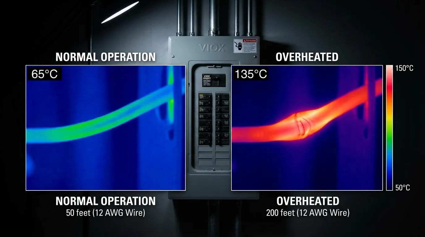
Folge: Während dieser 30-60 Sekunden wird der Draht zu einem riesigen Heizelement, das möglicherweise umliegende Materialien entzündet, bevor der Schutzschalter auslöst.
Professionelle Lösung
Stellen Sie bei langen Leitungsführungen immer sicher, dass prospektive Kurzschlussstrom den momentanen Auslöseschwellenwert des Schutzschalters übersteigt. Dies erfordert oft:
- Vergrößerung der Leiterquerschnitte über die Anforderungen des Spannungsfalls hinaus
- Installation von Unterverteilungen näher an den Lasten
- Verwendung einer höheren Spannung (240 V anstelle von 120 V)
Vergleichstabelle für Drahtgrößen-Upgrades
| Distanz | 120 V @ 20 A | 120 V @ 16 A | 240 V @ 20 A | Empfohlene Drahtgröße |
|---|---|---|---|---|
| 0-50 ft | 2,6 % VD | 2,1 % VD | 1,3 % VD | 12 AWG ✅ |
| 51-75 ft | 3,9 % VD | 3,1 % VD | 1,9 % VD | 10 AWG ⚠️ |
| 76-100 ft | 5,2 % VD | 4,1 % VD | 2,6 % VD | 10 AWG ⚠️ |
| 101-150 ft | 7,7 % VD | 6,2 % VD | 3,9 % VD | 8 AWG ⚠️ |
| 151-200 ft | 10,3 % VD | 8,3 % VD | 5,2 % VD | 6 AWG ⚠️ |
Legende: ✅ Akzeptabel | ⚠️ Upgrade erforderlich
Praktische Installationsrichtlinien
Wann 12/2-Draht akzeptabel ist
- ✅ Stromkreise in Wohngebäuden unter 50 Fuß
- ✅ Leichte Lasten (Beleuchtung, Steckdosen) unter 10 Ampere
- ✅ Kurze Strecken von Unterverteilungen zu nahegelegenen Steckdosen
- ✅ 240V-Stromkreise wo der Spannungsfall halbiert wird
Wann ein Upgrade von 12/2 erforderlich ist
- ⚠️ Entfernungen über 60 Fuß bei voller 20A-Last
- ⚠️ Motorlasten (Luftkompressoren, Elektrowerkzeuge), die einen hohen Anlaufstrom benötigen
- ⚠️ EV-Ladegeräte die kontinuierlich mit 16A+ betrieben werden
- ⚠️ Empfindliche Elektronik die eine stabile Spannung benötigen
- ⚠️ Gebäude im Freien 100+ Fuß vom Hauptpanel entfernt
Checkliste zur Einhaltung des NEC-Codes
Überprüfen Sie bei der Planung Ihrer 12/2-Drahtinstallation die Einhaltung dieser NEC-Anforderungen:
| Codeabschnitt | Anforderung | Compliance-Check |
|---|---|---|
| NEC 210.19(A)(1) | Spannungsfall im Abzweigstromkreis ≤ 3 % empfohlen | VD bei maximaler Last berechnen |
| NEC 240.4(D) | 12 AWG geschützt durch eine Überstromschutzeinrichtung mit max. 20A | 20A Sicherungsautomat verwenden (nicht 25A oder 30A) |
| NEC 310.16 | Leiterquerschnitt ausreichend für die Last | 12 AWG = 20A bei 60°C, 25A bei 90°C |
| NEC 110.14(C) | Temperaturfestigkeit der Anschlüsse | Die meisten Geräte sind für 60°C oder 75°C ausgelegt |
| NEC 334.80 | NM-Kabelstützung alle 4,5 Fuß | Romex ordnungsgemäß befestigen |
Kosten-Nutzen-Analyse: Wann sollte man den Kabelquerschnitt vergrößern?
Materialkostenvergleich (pro 100 Fuß)
| Drahtgröße | Ungefähre Kosten | Spannungsabfall @ 20A/100ft | Langfristiger Energieverlust |
|---|---|---|---|
| 12 AWG | $45-65 | 5.2% | $15-25/Jahr* |
| 10 AWG | $75-95 | 3.3% | $10-15/Jahr* |
| 8 AWG | $125-165 | 2.1% | $6-10/Jahr* |
*Basierend auf einer kontinuierlichen Last von 16A bei $0.12/kWh
ROI-Berechnung: Für eine 100-Fuß-Leitung mit einer kontinuierlichen Stromstärke von 16A:
- Die Aufrüstung von 12 AWG auf 10 AWG kostet $30 mehr
- Jährliche Energieeinsparungen: $10-15
- Amortisationszeit: 2-3 Jahre
- Verbesserung der Lebensdauer der Geräte: Motoren und Elektronik halten länger mit stabiler Spannung
Professionelle Empfehlung: Für jede dauerhafte Installation über 75 Fuß, Kabelquerschnitt um eine Nummer vergrößern. Die Grenzkosten sind minimal im Vergleich zu den langfristigen Leistungs- und Sicherheitsvorteilen.
Besondere Überlegungen für verschiedene Anwendungen
HLK- und Wärmepumpenkreise
Elektrische Heiz- und Kühlgeräte reagieren besonders empfindlich auf Spannungsabfall:
- Kompressormotoren ziehen einen hohen Anlaufstrom (LRA = Locked Rotor Amps)
- Reduzierte Spannung führt dazu, dass Motoren überhitzen und vorzeitig ausfallen
- Empfehlung: Spannungsabfall begrenzen auf 2 % Maximum für HLK-Kreise
EV-Ladestationen
Level-2-EV-Ladegeräte stellen besondere Herausforderungen dar:
- Dauerlast: Betrieb mit 80% der Nennleistung des Schutzschalters über Stunden
- Distanz: Oft in Garagen oder Einfahrten weit entfernt von der Schalttafel gelegen
- Lösung: Verwendung 240V-Stromkreise um den Spannungsabfallprozentsatz zu halbieren oder zu installieren dedizierte Unterverteilung
Solar-PV- und Batteriesysteme
DC-Kreise haben andere Überlegungen:
- Keine reaktive Impedanz: Nur der Widerstand zählt
- Höhere Spannungen: 48V-Systeme tolerieren Spannungsabfall besser
- Empfehlung: Befolgen Sie die NEC 690.8-Anforderungen für PV-Quellenstromkreise
Fehlersuche bei Spannungsabfallproblemen
Symptome von übermäßigem Spannungsabfall
- 🔴 Licht dimmt wenn Geräte starten
- 🔴 Motoren laufen heiß oder starten nicht
- 🔴 Elektronik setzt sich zurück oder funktioniert nicht richtig
- 🔴 GFCI-Fehlauslösungen auf langen Strecken
- 🔴 Geräte erbringen nicht die volle Leistung (langsames Erhitzen, schwache Kühlung)
Diagnoseschritte
- Spannung an der Schalttafel messen: Sollte 118-122V betragen (nominal 120V)
- Spannung an der Last unter Betrieb messen: Sollte innerhalb von 3 % der Spannung des Panels liegen
- Tatsächlichen Spannungsabfall berechnen: Panelspannung – Lastspannung
- Mit NEC-Empfehlungen vergleichen: 3 % = 3,6 V für 120-V-Stromkreise
Sanierungsoptionen
Option 1: Leiterquerschnitt vergrößern (dauerhafteste Lösung)
Option 2: Unterverteilung installieren näher an den Lasten
Option 3: Lasten neu verteilen zu kürzeren Stromkreisen
Option 4: Auf 240 V umstellen (für kompatible Geräte)
VIOX-Lösungen für Langstreckenverkabelung
Wenn Sie den Drahtquerschnitt vergrößern, um den Spannungsabfall zu überwinden, stoßen Sie auf ein häufiges Problem: größere Drähte passen nicht in Standard-Geräteklemmen.
VIOX-Produktanwendungen
1. Klemmenblöcke und Verteilerleisten
Beim Übergang von 8 AWG- oder 10 AWG-Zuleitungsdraht zu 12 AWG-Abzweigstromkreisen bieten VIOX-Klemmenblöcke:
- Sichere Verbindungen für gemischte Drahtstärken
- Code-konform Draht-zu-Draht-Übergänge
- Einfache Fehlersuche mit zugänglichen Anschlusspunkten
2. Hochleistungs-Anschlusskästen
Für lange Außenleitungen bieten die wetterfesten VIOX-Anschlusskästen:
- Schutzarten IP65/IP67 für raue Umgebungen
- Große Drahtkapazität für größere Leiterquerschnitte
- Zugentlastung für Übergänge in unterirdischen Leitungen
3. Unterverteilungslösungen
Die Installation einer Unterverteilung reduziert die Länge der Abzweigstromkreise:
- Hauptverteilung → Unterverteilung: 6 AWG oder größer verwenden
- Unterverteilung → Lasten: Standard 12 AWG für kurze Strecken
- Ergebnis: Optimaler Spannungsabfall in allen Stromkreisen
Häufig Gestellte Fragen
Kann ich ein 12/2-Kabel über eine Länge von 100 Fuß an einem 20-A-Schutzschalter betreiben?
Ja, aber mit Einschränkungen. Bei voller 20-A-Last beträgt der Spannungsabfall ungefähr 5.2%, und überschreitet die 3 %-Empfehlung des NEC. Dies ist akzeptabel für:
- Selten genutzte Lasten
- Stromkreise, die weniger als 12 Ampere ziehen
- 240-V-Stromkreise (der Spannungsabfall in Prozent wird halbiert)
Für Dauerlasten von 20 A, auf 10 AWG-Draht aufrüsten.
Beeinflusst die Drahtlänge das Auslösen des Schutzschalters?
Ja, deutlich. Längere Drahtwege erhöhen den Stromkreiswiderstand, was den Kurzschlussstrom reduziert. In extremen Fällen (über 60 Meter) kann der Fehlerstrom zu niedrig sein, um den unverzögerten magnetischen Auslöser des Schutzschalters auszulösen, was eine Brandgefahr. darstellt. Vergewissern Sie sich immer, dass der voraussichtliche Kurzschlussstrom das 5-fache des Nennstroms des Schutzschalters übersteigt.
Was ist der Unterschied zwischen 12/2- und 12/3-Draht für die Entfernung?
Die Drahtentfernungskapazität ist identisch. Die Zahlen beziehen sich auf die Anzahl der Leiter (2 oder 3 isolierte Leiter), nicht auf die Drahtstärke. Beide verwenden 12 AWG-Leiter mit dem gleichen Widerstand. Verwenden Sie 12/3, wenn Sie Folgendes benötigen:
- Dreiwegschalter-Stromkreise
- Mehrdraht-Abzweigstromkreise
- Separate stromführende Leiter für 240 V + Neutralleiter
Kann ich stattdessen Aluminiumdraht verwenden, um bei langen Leitungen Kosten zu sparen?
Ja, aber eine Nummer größer. Aluminium hat einen höheren Widerstand als Kupfer:
- Verwenden Sie 10 AWG Aluminium anstelle von 12 AWG Kupfer
- Erfordert Antioxydationsmittel auf Verbindungen
- Muss verwenden AL-taugliche Geräte (CO/ALR-Kennzeichnung)
- Kosteneinsparungen: 30-40 % günstiger für große Drahtquerschnitte
Wie berechne ich den Spannungsabfall für mehrere Steckdosen an einem Stromkreis?
Verwenden Sie die entfernteste Steckdose und maximale gleichzeitige Last. Zum Beispiel:
- Stromkreis hat 8 Steckdosen über 120 Fuß
- Annehmen 80 % der Leistung des Schutzschalters (16A für 20A Stromkreis)
- Berechnen Sie den Spannungsabfall bis zur letzten Steckdose bei 16A
- Dies bietet ein konservatives Worst-Case-Szenario
Beeinflusst der Kabeltyp (THHN vs. Romex) die maximale Entfernung?
NEIN. Der Spannungsabfall hängt nur ab von:
- Drahtstärke (AWG)
- Leitermaterial (Kupfer vs. Aluminium)
- Strom (Ampere)
- Entfernung (Fuß)
Isolationsart (THHN, THWN, NM-B) beeinflusst Strombelastbarkeit und Installationsmethode, aber nicht Widerstand oder Spannungsabfall.
Fazit: Der ingenieurtechnische Ansatz zur Drahtdimensionierung
Die Frage “Wie weit kann man ein 12/2-Kabel an einem 20-Ampere-Schutzschalter verlegen?” hat keine einfache Antwort – es hängt ab von:
- Systemspannung (120V vs. 240V)
- Tatsächlicher Laststrom (nicht nur Nennstrom des Schutzschalters)
- Akzeptabler Spannungsabfall (3 % empfohlen, 5 % maximal)
- Anwendungsempfindlichkeit (Motoren und Elektronik benötigen engere Toleranzen)
- Sicherheitsaspekte (Fehlerschleifenimpedanz für ordnungsgemäße Funktion des Schutzschalters)
Allgemeine Richtlinien:
- Unter 50 Fuß: 12 AWG ist für 20A-Stromkreise geeignet
- 50-75 Fuß: Erwägen Sie 10 AWG für Volllastanwendungen
- 75-100 Fuß: Verwenden Sie 10 AWG für 20A-Lasten
- Über 100 Fuß: Verwenden Sie 8 AWG oder installieren Sie einen Unterverteiler
Professionelle Best Practice: Im Zweifelsfall, eine Nummer größer wählen. Die Grenzkosten sind minimal im Vergleich zu den langfristigen Vorteilen von:
- Reduzierter Energieverschwendung
- Verlängerte Lebensdauer der Geräte
- Verbesserte Sicherheitsmargen
- Zukunftssichere Kapazität
Konsultieren Sie für komplexe Installationen oder kommerzielle Anwendungen einen zugelassenen Elektriker und erwägen Sie die Verwendung von VIOX-Elektrokomponenten , die für eine zuverlässige Stromverteilung über große Entfernungen ausgelegt sind.
Interne Links
Für verwandte technische Anleitungen siehe diese VIOX-Ressourcen:
- Leitfaden zur Auswahl der Drahtgröße für 50 Ampere – Umfassende Drahtdimensionierung für Stromkreise mit hoher Stromstärke
- Elektrische Reduzierung: Temperatur-, Höhen- und Gruppierungsfaktoren – Wie Umweltbedingungen die Drahtkapazität beeinflussen
- Leitfaden zum Höhen-Derating von Schutzschaltern – Kritische Überlegungen für Installationen in großer Höhe
- Kabelgrößen-Typen: mm² vs AWG vs BS Umrechnungsleitfaden – Internationale Drahtdimensionierungsstandards
- MCB Umgebungstemperaturbewertungen und Reduktionsfaktoren – Temperatureffekte auf den Schutz der Stromkreise
- So Berechnen Sie den Kurzschlussstrom für MCB – Verständnis der Fehlerstromberechnungen
- Standard-Leistungsschaltergrößen – Vollständiger Leitfaden zu Leistungsschalter-Nennwerten
- Leitfaden für Hausbesitzer zur Dimensionierung von Schutzschaltern und zur Lastberechnung – Praktische Richtlinien für die Wohnhausverkabelung
Über VIOX Electric: VIOX Electric ist ein führender B2B-Hersteller von elektrischen Geräten, spezialisiert auf Schutzschaltgeräte, Klemmenblöcke, Anschlusskästen und Verteilerlösungen für Wohn-, Gewerbe- und Industrieanwendungen. Unsere Produkte erfüllen oder übertreffen die NEC-, UL- und IEC-Normen für Sicherheit und Leistung.
