
In modern electrical systems, short-circuit faults can release devastating amounts of energy in milliseconds. A prospective fault current of 50,000 amperes generates magnetic forces powerful enough to bend busbars, thermal energy intense enough to vaporize copper conductors, and arc flash hazards that endanger personnel. Yet most of this destruction is preventable.
Current limiting circuit breakers represent a fundamental advancement in circuit protection technology. Unlike conventional breakers that interrupt faults at the natural zero crossing of the AC waveform, current-limiting breakers act within milliseconds to choke off the fault current before it reaches its destructive peak. This rapid intervention dramatically reduces the mechanical and thermal stress on electrical equipment, protects sensitive electronics from damage, and significantly mitigates arc flash hazards.
For electrical engineers designing distribution systems, panel builders selecting protection devices, and facility managers responsible for critical infrastructure, understanding current-limiting technology is essential. This guide explains how current-limiting circuit breakers work, the key specifications that define their performance, and when this technology delivers critical benefits over standard circuit protection.
What is a Current Limiting Circuit Breaker?
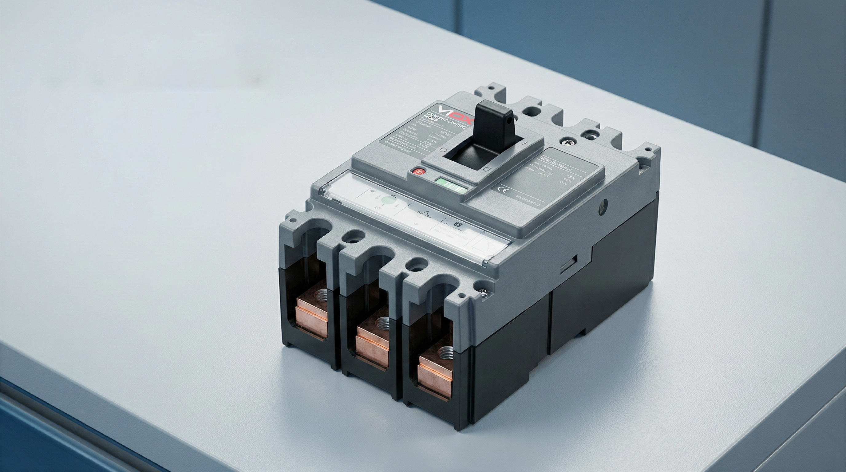
A current limiting circuit breaker is a protective device engineered to interrupt a short-circuit current before it reaches its maximum prospective peak value. This capability distinguishes it from conventional circuit breakers, which typically allow the fault current to reach its full peak before interrupting at a natural zero crossing.
When a short circuit occurs in an electrical system, the current begins rising at an extremely high rate—potentially reaching tens of thousands of amperes within milliseconds. A standard circuit breaker senses this fault condition and initiates its trip mechanism, but the interruption process takes time. During this brief interval, the fault current may reach its full prospective peak, releasing tremendous energy that stresses conductors, busbars, and downstream equipment.
Current limiting circuit breakers, by contrast, act with extraordinary speed. According to UL 489 (the North American standard for molded case circuit breakers), a circuit breaker qualifies as “current limiting” if it clears the fault in less than half a cycle—typically under 10 milliseconds. This rapid response introduces a high arc voltage that opposes the system voltage, effectively choking off the current flow and forcing the peak let-through current to a much lower value than the prospective fault current.
The result is dramatic: while a prospective fault current might be 50,000 amperes RMS symmetrical, a current-limiting breaker might limit the actual peak current to 15,000 amperes or less. This reduction in peak current and total fault energy protects downstream equipment from mechanical forces, thermal damage, and arc flash hazards that would otherwise occur.
How Current Limiting Circuit Breakers Work
The current-limiting capability of these circuit breakers results from a carefully engineered combination of mechanical design, electromagnetic physics, and arc management. The process unfolds in milliseconds through several coordinated mechanisms.
Electrodynamic Contact Separation
The first critical element is ultra-fast contact separation. When a high fault current flows through the breaker’s contacts, the enormous magnetic fields generated by this current create powerful electrodynamic forces. Current-limiting breakers are designed with contact configurations that harness these forces to assist separation—the contacts are arranged so the magnetic field creates a repulsive force that literally blows the contacts apart.
This “electrodynamic repulsion” means that higher fault currents actually accelerate contact separation. The breaker doesn’t rely solely on the mechanical force of the trip mechanism; the fault current itself contributes energy to open the contacts faster. This ensures extremely rapid contact separation—often within 1-2 milliseconds of fault initiation.
Arc Formation and Elongation
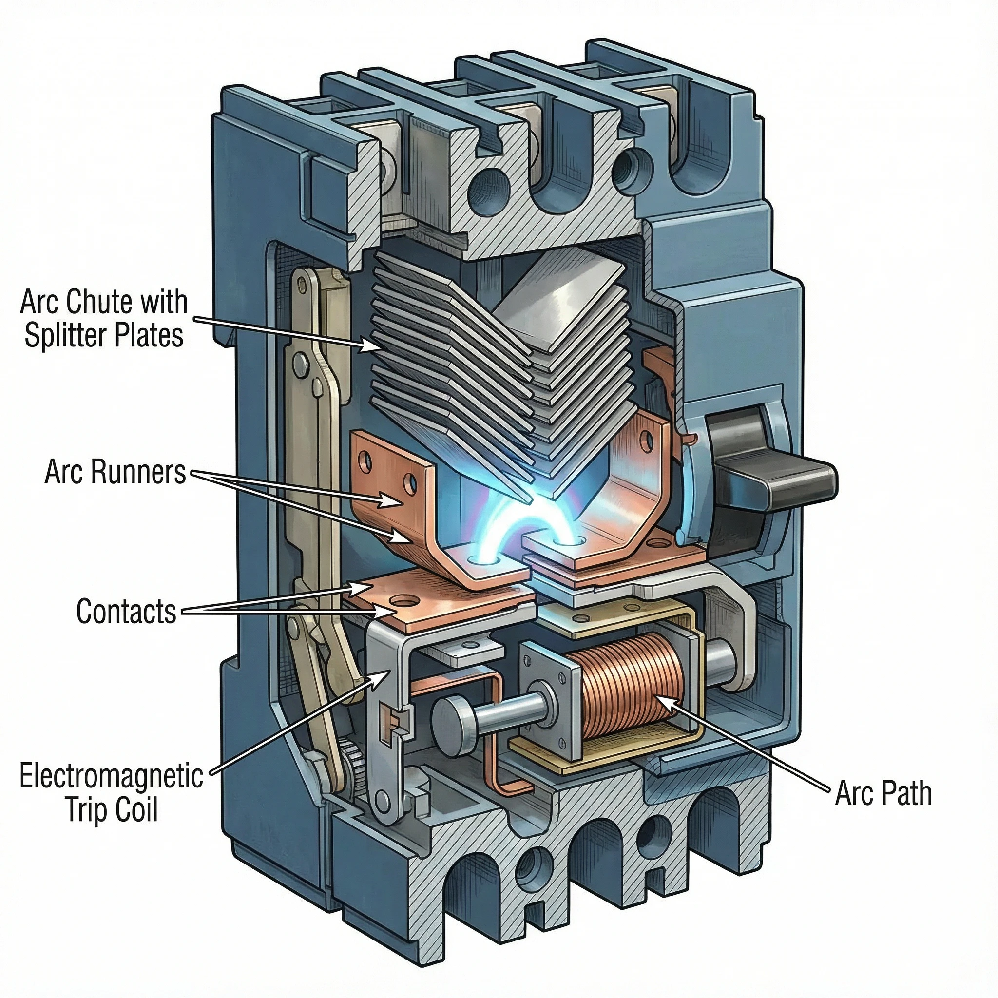
As the contacts separate at high speed, an electrical arc forms in the gap. Rather than being a problem to suppress, this arc becomes the primary tool for current limitation. The breaker’s internal geometry is designed to force this arc to move rapidly away from the contacts and into a specially designed arc chamber called an arc chute.
Magnetic fields generated by the current flow and the physical shape of the arc runners guide the arc upward into the arc chute. As the arc moves and stretches, its length increases dramatically. A longer arc requires higher voltage to sustain it, and this arc voltage opposes the system voltage driving the fault current.
Arc Commutation and Splitting
The arc chute contains a series of metal plates arranged in a specific configuration (often V-shaped), called arc splitters or arc dividers. As the arc is driven into the chute, it contacts these plates and “commutates”—transferring from the main arc path to the splitter plates.
This process effectively splits the single high-energy arc into multiple smaller arcs in series. Each small arc develops its own voltage drop. If the arc chute contains, for example, 20 splitter plates, the total arc voltage can reach many times the system voltage. When the cumulative arc voltage exceeds the system voltage, the current is forced to decrease rapidly.
Arc Cooling and Extinction
The metal splitter plates also serve as heat sinks, rapidly cooling the arcs. The plates increase the arc’s surface area and conduct heat away. Combined with surrounding air or arc-quenching gases, this cooling reduces the arc’s conductivity.
The interplay of high arc voltage (opposing current flow) and arc cooling (reducing conductivity) forces the current toward zero. The breaker extinguishes the arc and clears the fault—all within a fraction of a cycle, before the fault current reaches its prospective peak.
This entire sequence—from fault detection through contact separation, arc elongation, splitting, and extinction—occurs in under 10 milliseconds. The current is interrupted not at a natural zero crossing but forcibly, by creating conditions where the arc cannot be sustained.
Wichtige technische Spezifikationen
Understanding current-limiting performance requires familiarity with three critical specifications that define how effectively a breaker limits fault current and protects downstream equipment.
Let-Through Current (Ip)
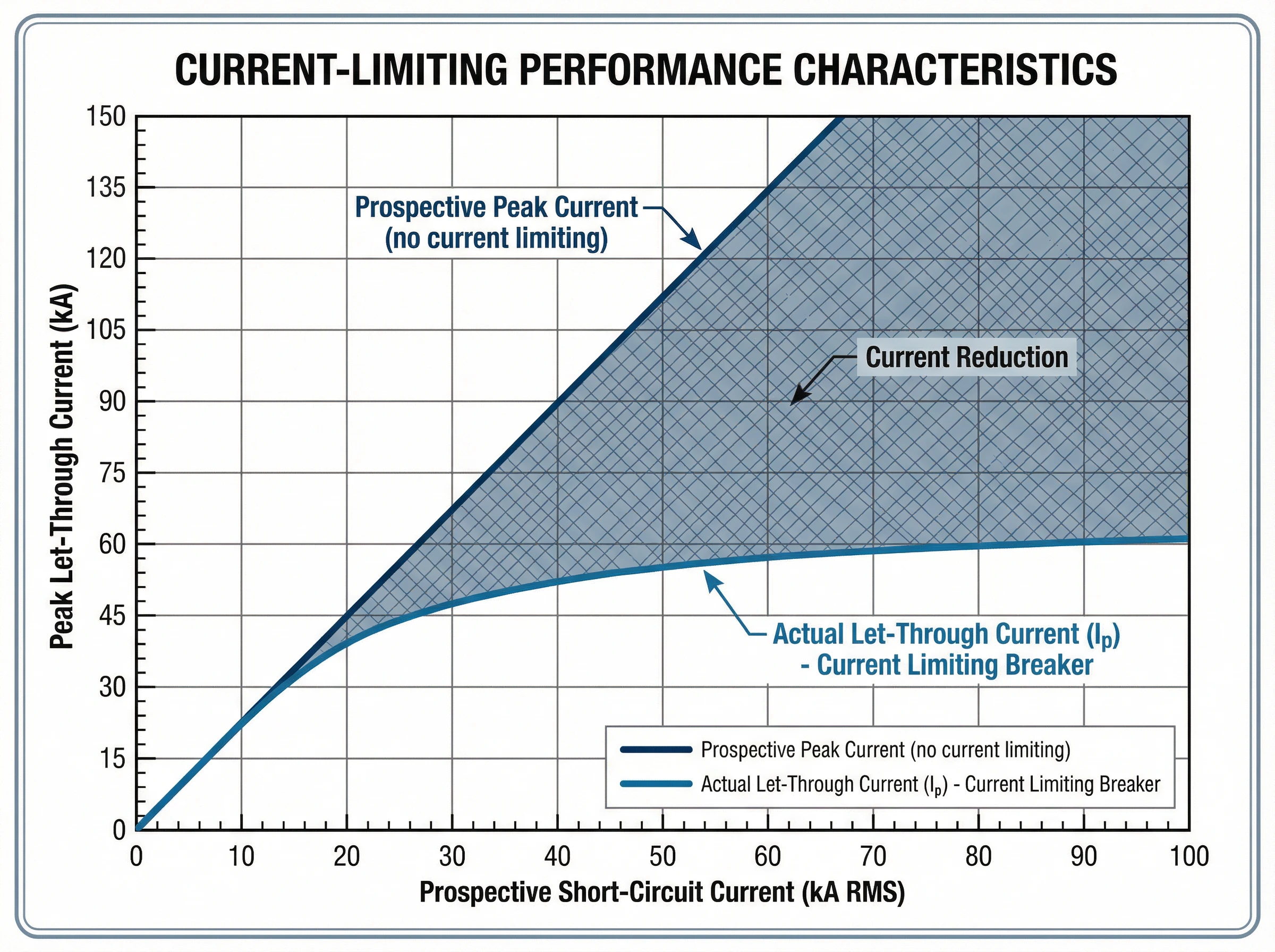
Die let-through current (Ip) is the actual peak current that flows through the breaker during a fault, measured in amperes. This value represents the breaker’s current-limiting effectiveness: a lower Ip indicates better current limitation.
Manufacturers provide let-through current data in the form of characteristic curves. These graphs plot the peak let-through current (Ip) on the vertical axis against the prospective short-circuit current (RMS symmetrical amperes) on the horizontal axis. For any given prospective fault level at the installation point, the curve shows the maximum peak current that will actually flow.
For example, if the available fault current at a panelboard is 42,000 amperes RMS symmetrical, a current-limiting breaker might limit the actual peak current to just 18,000 amperes. This reduction from prospective to actual peak current protects busbars from bending, prevents conductor overheating, and reduces mechanical stress on all downstream components.
Thermal Stress (I²t)
Die I²t value (pronounced “I-squared-t”), measured in ampere-squared seconds (A²s), quantifies the thermal energy let through by the breaker during fault clearing. It represents the integral of the current squared over the total clearing time.
This specification is critical for protecting cables and sensitive electronic equipment. The insulation of cables has a specific thermal withstand rating expressed as I²t. If the protective device lets through more thermal energy than the cable can withstand, the insulation will be damaged even if the cable doesn’t physically melt.
Current-limiting breakers dramatically reduce I²t compared to standard breakers. For the same prospective fault current, a current-limiting device might have an I²t value 50-80% lower than a conventional breaker. This reduced thermal stress prevents conductor damage, protects cable insulation, and extends equipment life.
Manufacturers provide I²t curves similar to let-through current curves, showing the maximum thermal energy as a function of prospective fault current. Some standards define energy-limiting classes for circuit breakers based on their I²t performance.
Breaking Capacity (Icu and Ics)
Die Schaltleistung defines the maximum fault current the breaker can safely interrupt. Two ratings are relevant under IEC 60947-2 (the international standard for low-voltage circuit breakers):
- Bruchfestigkeit (Icu): The maximum fault current the breaker can interrupt without being destroyed. After interrupting a fault at Icu level, the breaker may not be suitable for continued service and might require replacement. This represents the breaker’s absolute upper limit.
- Ausschaltvermögen (Ics): The maximum fault current the breaker can interrupt multiple times while remaining fully functional and reliable for continued service. Ics is expressed as a percentage of Icu (typically 50%, 75%, or 100%). For critical applications requiring high reliability, breakers with Ics = 100% Icu are preferred.
The fundamental selection rule is straightforward: the breaker’s Icu must be equal to or greater than the prospective short-circuit current at the point of installation. Current-limiting breakers can achieve high breaking capacities (50kA, 85kA, or higher) in compact form factors because the current-limiting action itself reduces the energy the breaker must handle.
The Interrelationship of Specifications
These specifications work together to define protection performance. When a fault occurs up to the breaker’s Icu rating, the current-limiting action reduces both the peak current (Ip) and the total thermal energy (I²t) to values far below what the prospective fault would produce. This coordinated reduction in peak mechanical stress and thermal damage is what makes current-limiting breakers essential for protecting modern electrical systems with high available fault currents.
Standards and Compliance
Current-limiting circuit breakers are governed by rigorous international and regional standards that define performance requirements, testing procedures, and safety criteria.
IEC 60947-2: International Standard
IEC 60947-2 is the international standard for low-voltage circuit breakers used in industrial and commercial applications. This comprehensive standard establishes:
- Performance categories: The standard distinguishes between Category A breakers (no intentional short-circuit time delay) and Category B breakers (with short-time withstand capability). Most modern current-limiting MCCBs are Category A devices.
- Breaking capacity verification: IEC 60947-2 specifies rigorous test sequences to verify both ultimate breaking capacity (Icu) and service breaking capacity (Ics). These tests involve multiple making and breaking operations under specified fault conditions.
- Current-limiting performance: While the standard doesn’t mandate current limitation, it provides test procedures to verify and document let-through current and I²t performance for breakers claiming current-limiting capability.
- Coordination and selectivity: The standard establishes requirements for back-up protection (cascading), where a current-limiting breaker upstream protects a downstream breaker with lower breaking capacity than the prospective fault current at its location.
UL 489: North American Standard
UL 489 is the Underwriters Laboratories standard for molded case circuit breakers in North America. Key provisions include:
- Current-limiting definition: UL 489 specifies that a circuit breaker qualifies as “current limiting” if it clears a fault in less than half a cycle (typically under 10 milliseconds for 60 Hz systems).
- Durchlassprüfung: Die Norm erfordert umfangreiche Tests, um Durchlassstromkurven zu erstellen, die den tatsächlichen Spitzenstrom als Funktion des voraussichtlichen Fehlerstroms zeigen.
- Kurzschlussfestigkeit: UL 489 definiert Abschaltvermögen (IR) und legt Testverfahren fest, um die Leistung des Schutzschalters bei Nennspannung und -strom zu überprüfen.
Konformität und Zertifizierung
Für Konstrukteure und Planer von elektrischen Systemen stellt die Einhaltung von Normen Folgendes sicher:
- Geprüfte Leistung: Zertifizierte Schutzschalter wurden strengen Tests durch Dritte unterzogen, um ihre Strombegrenzungsfähigkeit und ihr Schaltvermögen zu bestätigen.
- Planungssicherheit: Ingenieure können sich auf veröffentlichte Durchlasskurven und I²t-Daten für die Analyse des Geräteschutzes und die Berechnung des Störlichtbogens verlassen.
- Gesetzliche Akzeptanz: Normenkonforme Schutzschalter erfüllen die Anforderungen der Elektrovorschriften in ihren jeweiligen Märkten (IEC-Zonen oder nordamerikanische Installationen).
VIOX-Strombegrenzungsschutzschalter sind so konzipiert und geprüft, dass sie sowohl die Anforderungen der IEC 60947-2 als auch der UL 489 erfüllen und so globale Anwendbarkeit und geprüfte Schutzleistung gewährleisten.
Anwendungen und Use Cases
Strombegrenzungsschutzschalter bieten entscheidende Vorteile in elektrischen Systemen, in denen hohe verfügbare Fehlerströme die Geräteintegrität und die Sicherheit des Personals gefährden.
Rechenzentren und kritische IT-Infrastruktur
Moderne Rechenzentren stehen vor außergewöhnlichen Herausforderungen durch Fehlerströme. Serverracks mit hoher Dichte, leistungsstarke USV-Anlagen und mehrere Netzzuleitungen erzeugen verfügbare Fehlerströme, die 65 kA oder mehr übersteigen können. Strombegrenzungsschutzschalter sind in diesen Umgebungen unerlässlich:
- Schutz der IT-Ausrüstung: Server, Speicherarrays und Netzwerkgeräte enthalten empfindliche Elektronik, die selbst bei kurzen Überstromereignissen anfällig ist. Strombegrenzungsschutzschalter reduzieren die Fehlerenergie auf ein Niveau, das Komponentenschäden verhindert.
- Selektive Koordination: Die Zuverlässigkeit von Rechenzentren hängt von der Isolierung von Fehlern ab, ohne dass es zu kaskadierenden Ausfällen kommt. Strombegrenzungsschutzschalter erleichtern die Koordination zwischen vor- und nachgeschalteten Schutzvorrichtungen und stellen sicher, dass nur der betroffene Stromkreis auslöst.
- Störlichtbogenminderung: Wartungspersonal arbeitet regelmäßig an unter Spannung stehenden Geräten. Durch die Reduzierung des Spitzenfehlerstroms und der Abschaltzeit senken Strombegrenzungsschutzschalter die Störlichtbogen-Ereignisenergie drastisch, verbessern die Arbeitssicherheit und reduzieren möglicherweise die Anforderungen an die PSA.
- Kompakte Installationen: Die Strombegrenzungstechnologie ermöglicht ein hohes Schaltvermögen (50 kA-100 kA) in kompakten MCCBs und unterstützt eine dichte Stromverteilung, ohne dass überdimensionierte Schaltanlagen erforderlich sind.
Industrielle Fertigungsanlagen
Industrieanlagen mit großen Motoren, Transformatoren und umfangreichen Verteilungsnetzen sind mit Fehlerströmen konfrontiert, die Produktionsanlagen beschädigen können:
- Motorsteuerungszentren: Schutz von Motorstartern, Frequenzumrichtern und Steuerungselektronik vor Fehlerstrombelastung. Strombegrenzungsschutzschalter verhindern Schäden an teurer Antriebselektronik und gewährleisten die Produktionskontinuität.
- Hochleistungsfähige Zuleitungen: Wenn mehrere Stromquellen oder große Transformatoren Fehlerströme von mehr als 50 kA erzeugen, bieten Strombegrenzungsschutzschalter Schutz, ohne dass teure Schaltanlagen mit hohem Schaltvermögen im gesamten System erforderlich sind.
- Schutz der Ausrüstung: Stromschienen, Kabeltrassen und Schalttafelkomponenten haben mechanische Festigkeitsgrenzen. Strombegrenzungsschutzschalter reduzieren die magnetischen Kräfte bei Fehlern und verhindern so physische Schäden an der Verteilungsinfrastruktur.
Gewerbebauten mit hoher Leistungsdichte
Bürotürme, Krankenhäuser und Einzelhandelszentren setzen zunehmend auf Hochleistungssysteme:
- Haupt- und Unterverteilung: Strombegrenzungsschutzschalter an den Haupteinspeisungen und Verteilertafeln schützen vor netzseitigen Fehlerströmen und ermöglichen gleichzeitig eine effektive nachgeschaltete Koordination.
- Notstromanlagen: Schutz von Generatoren und Transferschaltern, bei denen mehrere Quellen den verfügbaren Fehlerstrom erhöhen.
- Renovierung und Erweiterung: Das Hinzufügen von Kapazität zu bestehenden Gebäuden erhöht oft die Fehlerstrompegel. Strombegrenzungsschutzschalter können manchmal die Notwendigkeit vollständiger System-Upgrades beseitigen, indem sie einen angemessenen Schutz innerhalb der bestehenden Infrastrukturbewertungen bieten.
Kaskadenschutz (Backup-Schutz)
Eine der wertvollsten Anwendungen ist die Ermöglichung von Kaskaden- oder Serienbemessung. Ein vorgeschalteter Strombegrenzungsschutzschalter kann nachgeschaltete Schutzschalter mit einem geringeren Schaltvermögen schützen als der voraussichtliche Fehlerstrom an ihrem Standort. Dies ermöglicht:
- Kostenoptimierung: Verwendung von kostengünstigeren, niedriger bewerteten Schutzschaltern nachgeschaltet unter Beibehaltung des vollen Schutzes.
- Vereinfachte Spezifikation: Standardisierung auf gängige Schutzschaltertypen in der gesamten Anlage, während der strombegrenzende Hauptschutzschalter einen systemweiten Schutz bietet.
- Systemflexibilität: Hinzufügen von Stromkreisen oder Lasten, ohne unbedingt alle nachgeschalteten Schutzvorrichtungen aufzurüsten.
Strombegrenzung vs. Standard-Leistungsschalter
Das Verständnis des Unterschieds zwischen strombegrenzenden und Standard-Leistungsschaltern verdeutlicht, wann welche Technologie geeignet ist.
Unterbrechungsmethode
Standard-Leistungsschalter: Konventionelle Leistungsschalter erkennen einen Fehler und leiten den Auslösemechanismus ein, lassen aber zu, dass der Fehlerstrom auf seinen voraussichtlichen Spitzenwert ansteigt. Die Unterbrechung erfolgt an oder in der Nähe eines natürlichen Stromnulldurchgangs, typischerweise nach 0,5 bis 1,5 Zyklen (8-25 Millisekunden bei 60 Hz). Während dieser Zeit belastet der volle Fehlerstrom das System.
Strombegrenzende Leistungsschalter: Diese Geräte wirken innerhalb von Millisekunden, um den Strom zwangsweise zu unterbrechen, bevor er seinen voraussichtlichen Spitzenwert erreicht. Durch elektrodynamische Kontakttrennung und Lichtbogenspannungsaufbau beseitigen sie den Fehler in weniger als einem halben Zyklus (unter 10 Millisekunden) und reduzieren so sowohl den Spitzenstrom als auch die gesamte Fehlerenergie drastisch.
Spitzenstrom und mechanische Belastung
Standard-Leistungsschalter: Der volle voraussichtliche Fehlerstrom fließt und erzeugt maximale magnetische Kräfte. Bei einem voraussichtlichen Fehler von 50 kA erzeugt der volle Wert von 50 kA (70 kA asymmetrisch in der Spitze) eine enorme mechanische Belastung auf Stromschienen, Klemmen und Verbindungen.
Strombegrenzende Leistungsschalter: Der Durchlassstrom wird deutlich reduziert. Für denselben voraussichtlichen Fehler von 50 kA könnte ein strombegrenzender Schutzschalter die tatsächliche Spitze auf 15-20 kA begrenzen, wodurch die magnetischen Kräfte um 60-70% reduziert werden.
Thermische Energie (I²t)
Standard-Leistungsschalter: Längere Abschaltzeiten und höhere Spitzenströme führen zu einer erheblichen Freisetzung thermischer Energie. Kabel, Stromschienen und Verbindungen absorbieren erhebliche Wärme, die möglicherweise die Isolierung beschädigt.
Strombegrenzende Leistungsschalter: Reduzierter Spitzenstrom und ultraschnelle Abschaltung senken die I²t-Werte drastisch, oft um 50-80%. Dies schützt die Kabelisolierung, verhindert das Ausglühen der Leiter und schützt empfindliche Elektronik vor thermischer Belastung.
Störlichtbogen-Ereignisenergie
Standard-Leistungsschalter: Höherer Fehlerstrom und längere Abschaltzeiten erhöhen die Störlichtbogen-Ereignisenergie, was eine höhere PSA-Stufe erfordert und größere Sicherheitsrisiken für das Wartungspersonal schafft.
Strombegrenzende Leistungsschalter: Reduzierte Fehlerstromstärke und -dauer verringern die Störlichtbogenenergie erheblich. Dies kann die Störlichtbogengrenze senken, die PSA-Anforderungen reduzieren und die allgemeine elektrische Sicherheit verbessern.
Kosten- und Komplexitäts-Kompromisse
Standard-Leistungsschalter: Im Allgemeinen pro Einheit weniger teuer. Geeignet für Anwendungen, bei denen die Fehlerströme moderat sind und die Geräteleistungen die verfügbaren Fehlerstrompegel ausreichend übersteigen.
Strombegrenzende Leistungsschalter: Höhere Anschaffungskosten, können aber die Gesamtsystemkosten senken durch:
- Ermöglichen von leichteren nachgeschalteten Komponenten
- Ermöglichen von Kaskadenschutz mit niedriger bewerteten Schutzschaltern
- Reducing panel reinforcement requirements
- Protecting expensive equipment from damage
- Lowering arc flash mitigation costs
Wann ist welcher Typ auszuwählen?
Choose Standard Breakers when:
- Available fault current is well below the system’s short-circuit rating
- Budget constraints are paramount and fault levels don’t justify current-limiting protection
- Coordination can be achieved without current limitation
Choose Current-Limiting Breakers when:
- Available fault currents exceed 20-25kA
- Protecting sensitive electronic equipment (data centers, control systems)
- Seeking arc flash hazard reduction
- Enabling cascading protection to reduce costs
- Facility expansion has increased fault levels beyond original equipment ratings
Kriterien für die Auswahl
Selecting the right current-limiting circuit breaker requires evaluating several technical and application factors.
Calculate Available Fault Current
The first step is determining the prospective short-circuit current at the installation point. This requires:
- Utility transformer capacity and impedance
- Conductor lengths and sizes
- Impedance of distribution components
- Contribution from motors and generators
Many utilities provide fault current data, or qualified electrical engineers can perform short-circuit calculations using industry-standard methods (IEC 60909 or IEEE standards). The breaker’s ultimate breaking capacity (Icu) must meet or exceed this calculated fault current.
Evaluate Equipment Protection Requirements
Consider what needs protection:
- Empfindliche Elektronik: Data centers, control systems, and telecommunications equipment benefit significantly from reduced let-through current and I²t.
- Busbar and conductor ratings: If fault currents approach or exceed the short-circuit withstand ratings of busbars, cables, or panel components, current limitation becomes essential.
- Existing equipment: When expanding facilities, current-limiting breakers can sometimes protect existing infrastructure without requiring complete replacement.
Assess Arc Flash Hazard Mitigation Needs
If arc flash studies indicate high incident energy levels requiring extensive PPE or creating unacceptable worker hazards, current-limiting breakers can significantly reduce arc flash energy. Review arc flash calculations to determine if current limitation would lower the hazard category and improve safety.
Consider Coordination Requirements
Selective coordination—ensuring only the breaker nearest the fault trips—is critical in many applications:
- Cascading protection: If downstream breakers have breaking capacities lower than available fault current, a current-limiting breaker upstream can provide back-up protection.
- Critical loads: Data centers, hospitals, and industrial processes require fault isolation without unnecessary outages. Current-limiting breakers facilitate coordination by reducing let-through energy.
Review Let-Through Current Curves
Manufacturers provide let-through current (Ip) and I²t curves for their current-limiting breakers. Compare these curves against:
- Equipment withstand ratings
- Cable I²t limits
- Arc flash energy reduction targets
- Coordination requirements with downstream devices
Verify Standards Compliance
Ensure the breaker meets applicable standards:
- IEC 60947-2 for international/industrial applications
- UL 489 for North American installations
- Local electrical codes and certification requirements
Fazit
Current-limiting circuit breakers represent a critical advancement in electrical protection technology, addressing the fundamental challenge of high fault currents in modern power systems. By interrupting faults in milliseconds and dramatically reducing peak let-through current and thermal stress, these devices protect expensive equipment, improve personnel safety, and enable more flexible system designs.
For electrical engineers and facility managers working with high-power distribution systems—particularly data centers, industrial facilities, and commercial buildings with fault currents exceeding 25kA—current-limiting technology delivers measurable benefits in equipment protection, arc flash mitigation, and coordination flexibility. The key specifications (let-through current Ip, thermal stress I²t, and breaking capacity Icu) provide the engineering data needed to verify protection performance and ensure safe, reliable operation.
VIOX Electric manufactures current-limiting circuit breakers engineered to IEC 60947-2 and UL 489 standards, offering breaking capacities from 35kA to 100kA and comprehensive let-through performance curves. For technical specifications, application guidance, or to discuss your specific protection requirements, contact VIOX’s engineering team.
Protect your critical infrastructure with proven current-limiting technology. Kontakt zu VIOX Electric to discuss your circuit protection needs.
