

Auf dieser Seite
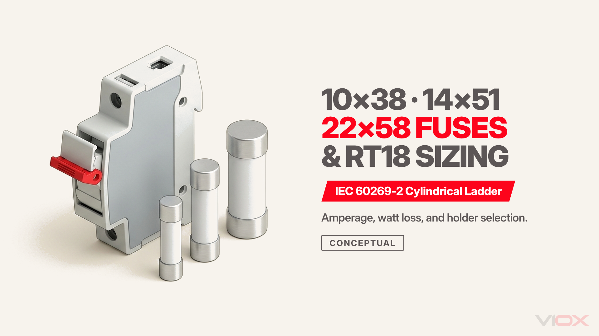
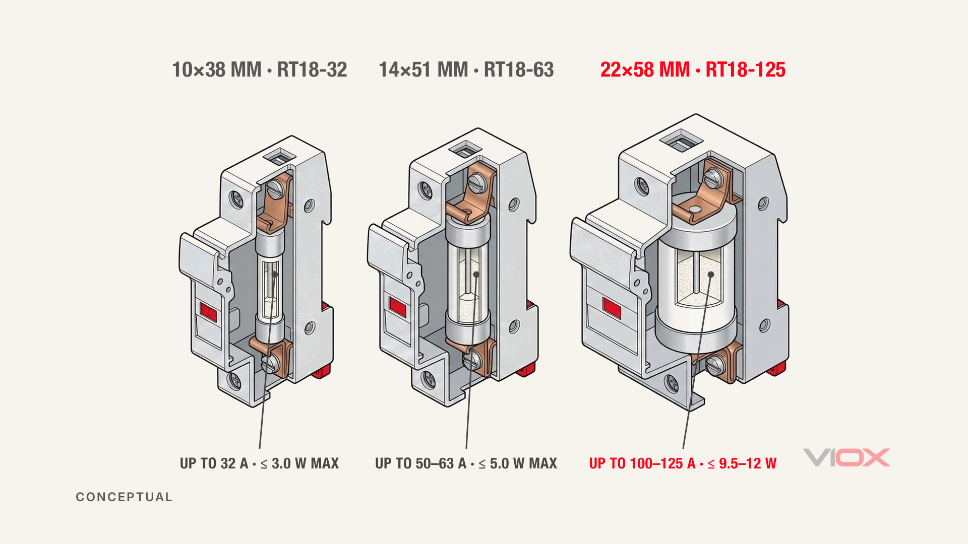
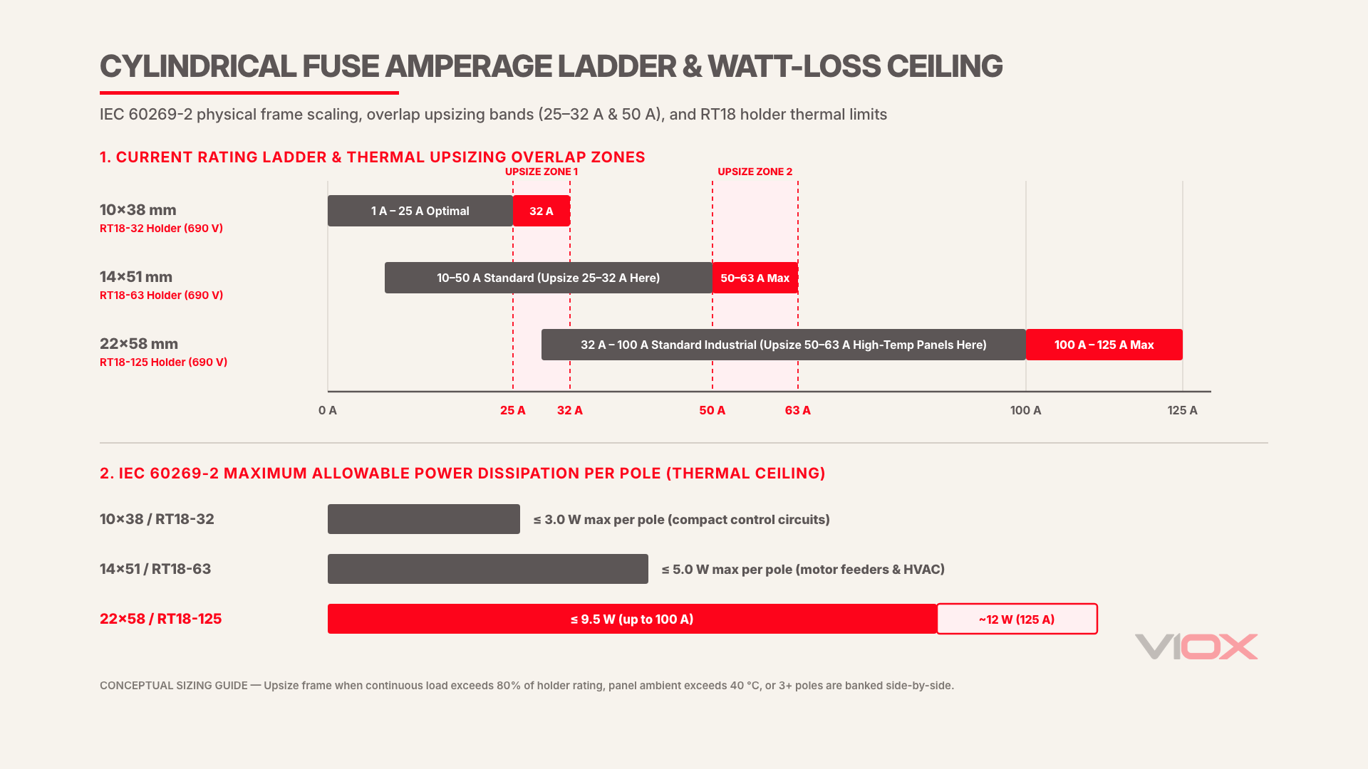
Unter IEC 60269-2, industrial cylindrical fuses scale across three standard body dimensions paired directly with modular DIN-rail RT18 holders: 10×38 mm passt RT18-32 holders up to 32 A (≤ 3.0 W max dissipation), 14×51 mm passt RT18-63 holders up to 50 A–63 A (≤ 5.0 W max), and 22×58 mm passt RT18-125 holders up to 100 A–125 A (≤ 9.5 W to 12 W max). Selecting the right frame depends on both rated current and enclosed panel heat dissipation.
Engineering Scope: This sizing guide covers industrial AC cylindrical ferrule fuse-links and DIN-rail RT18 modular fuse holders governed by IEC 60269-2 (up to 690 V AC), alongside the strict non-interchangeability boundary for 10×38 mm solar PV DC fuses governed by IEC 60269-6. Exact breaking capacities, terminal torque values, and ambient derating curves are governed by each component’s qualification datasheet.
10×38 vs. 14×51 vs. 22×58 Cylindrical Fuse Master Sizing Chart
The three IEC 60269-2 industrial cylindrical fuse sizes—10×38 mm, 14×51 mm, and 22×58 mm—differ in ferrule diameter, ceramic arc-quenching volume, maximum allowable watt loss, and matching DIN-rail holder frame. Matching the fuse-link dimensions precisely to the RT18 holder prevents high-resistance contact heating and ensures rated short-circuit interruption.
| Specification Parameter | 10×38 mm Cylindrical Fuse | 14×51 mm Cylindrical Fuse | 22×58 mm Cylindrical Fuse |
|---|---|---|---|
| Physical Dimensions (Diameter × Length) | 10.3 mm × 38 mm | 14.3 mm × 51 mm | 22.2 mm × 58 mm |
| Typical Rated Current Ladder (gG / aM) | 1 A to 32 A (optimal ≤ 25 A continuous) | 2 A to 50 A (holders rated up to 63 A) | 16 A to 125 A (optimal 32 A–100 A) |
| Standard Industrial AC Voltage Range | 400 V / 500 V / 690 V AC | 400 V / 500 V / 690 V AC | 500 V / 690 V AC |
| IEC 60269-2 Max Power Dissipation per Pole | ≤ 3.0 W | ≤ 5.0 W | ≤ 9.5 W (to 100 A) / ~12 W (125 A) |
| Matching VIOX DIN-Rail Holder | VIOX RT18-32 (690 V, 32 A, 1–4P) | VIOX RT18-63 (690 V, 63 A, 1–4P) | VIOX RT18-125 (690 V, 125 A, 1–4P) |
| Primary Industrial Panel Role | PLC power, control transformers, metering, small auxiliary drives | Motor branch feeders, HVAC compressors, pumps, industrial heaters | Sub-main feeders, capacitor banks, heavy machinery distribution |
Auswahlregel: Pair VIOX cylindrical fuse links (250 V–500 V, up to 125 A) strictly with the matching RT18 holder frame—use 10×38 mm / RT18-32 for control and auxiliary circuits up to 25 A continuous, step up to 14×51 mm / RT18-63 for 25 A–50 A feeders, and specify 22×58 mm / RT18-125 for 50 A–125 A distribution loads.
Amperage Overlap Zones and IEC 60269-2 Watt-Loss Derating
Because 10×38 mm, 14×51 mm, and 22×58 mm cylindrical fuses overlap at 25 A–32 A and 50 A–63 A, selecting the smallest frame that nominally covers the load current often causes premature holder thermal failure. IEC 60269-2 caps per-pole power dissipation by physical size, making enclosure temperature and multi-pole banking decisive factors in overlap zones.
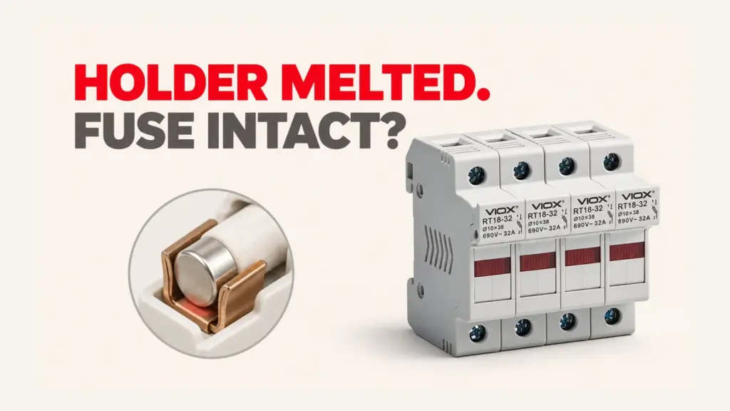
Inside a tightly packed control cabinet, every cylindrical fuse link generates continuous I²R heat that must dissipate through the spring-clip terminals and polymer housing of the DIN-rail holder. When a 32 A fuse link runs continuously at 90% to 100% load inside a 10×38 mm holder banked directly beside neighboring heat-generating poles, terminal temperatures can climb past polymer softening limits—producing charred or deformed housings even though the fuse element never melts. For field diagnosis of this exact failure mechanism, see why a fuse holder melts when the fuse has not blown.
| Overlap Current Band | Lower Frame Option | Upsized Frame Option | Mandatory Upsize Trigger Conditions |
|---|---|---|---|
| 25 A to 32 A | 10×38 mm in RT18-32 (≤ 3.0 W ceiling) | 14×51 mm in RT18-63 (≤ 5.0 W ceiling) | Continuous load > 80% of 32 A (> 25.6 A), panel ambient > 40 °C, 3P/3P+N side-by-side banking without spacers, or 690 V AC high breaking demand |
| 50 A to 63 A | 14×51 mm in RT18-63 (≤ 5.0 W ceiling) | 22×58 mm in RT18-125 (≤ 9.5 W–12 W ceiling) | Continuous duty > 40 A in enclosed cabinets, motor-starting aM inrush cycling, or ambient enclosure temperatures ≥ 45 °C |
Sizing Rule: In both overlap bands, treat the lower frame’s maximum rating as an intermittent ceiling rather than a 24/7 continuous operating point; whenever continuous current exceeds 80% of holder rating or ambient panel temperature exceeds 40 °C, step up to the next RT18 frame to gain higher thermal mass and lower contact temperature rise.
RT18 Fuse Holder Sizing: Poles, Indicators (RT18 vs. RT18X), and Load-Break Limits
Correct RT18 fuse holder sizing goes beyond matching millimeter dimensions—panel builders must also specify pole architecture (1P through 4P), blown-fuse indication (RT18 vs. RT18X), and operational switching boundaries under IEC 60947-3. Misapplying a standard modular fuse holder as a live load-break switch creates an immediate arc-flash hazard.
VIOX’s DIN-rail RT18-32, RT18-63und RT18-125 series are rated to 690 V AC across 1-pole to 4-pole configurations with tool-free flip-open fuse carriers. Three configuration checks prevent procurement and commissioning errors:
| Configuration Feature | Standard Option | Variant / Upgrade Option | Engineering Selection Criterion |
|---|---|---|---|
| Blown-Fuse Indication | RT18 (no indicator) | RT18X (integrated neon/LED status lamp) | Specify RT18X on multi-feeder control panels to pinpoint blown phases instantly without live multimeter probing; verify minimum operating voltage for indicator illumination |
| Pole Architecture | 1P, 2P, 3P (fused phase poles) | 1P+N, 3P+N (solid neutral disconnect link) | Use 3P for balanced three-phase motors and 3P+N where neutral isolation is required during servicing without placing a fusible element in the neutral |
| Utilization Class Pairing | gG (full-range cable and general protection) | aM (short-circuit-only motor backup) | Pair aM cylindrical links strictly with a downstream thermal overload relay; for full IEC 60269 class rules, see our IEC 60269 gG and aM selection guide |
| Switching Duty Limit | Off-load isolation only (IEC 60269-2 holder) | Fused switch-disconnector (IEC 60947-3 AC-22B / AC-23B) | Never pull open an RT18 carrier under active load current; install an upstream load-break switch or dedicated disconnector |
Sicherheitsregel: Standard RT18 DIN-rail fuse holders contain no arc-extinguishing chutes and are strictly off-load isolation devices—always de-energize the circuit upstream before opening the carrier, or specify an IEC 60947-3 rated unit as detailed in fuse holder vs. fuse switch disconnector load-break safety.
Critical Non-Interchangeability: AC 10×38 (RT18-32) vs. 1000V DC Solar gPV 10×38
Although industrial AC 10×38 mm fuses and solar photovoltaic gPV 10×38 mm fuses share the exact same 10.3 mm × 38 mm mechanical footprint, they are electrically non-interchangeable. Installing a standard AC RT18-32 holder on a 1,000 V DC or 1,500 V DC photovoltaic string violates IEC 60269-6 and risks sustained DC arcing and housing ignition.
Direct current lacks the natural 50/60 Hz current zero-crossings that help extinguish AC arcs. Under IEC 60269-6, gPV 10×38 mm fuse links are engineered to interrupt low-multiple DC fault currents (down to roughly 1.35× to 2× rated current) across 1,000 V DC to 1,500 V DC, and require dedicated DC-rated holders with extended creepage distances, reinforced dielectric barriers, and DC voltage qualification—such as the VIOX DC-Sicherungshalter VOR-32 Serie.
Boundary Rule: Restrict RT18-32 (690 V AC) holders strictly to AC industrial control, distribution, and auxiliary circuits; for any 1,000 V DC or 1,500 V DC solar PV string or BESS branch, specify IEC 60269-6 gPV fuse links paired exclusively with a DC-rated 10×38 mm holder.
Industrial Applications by Frame Size (and When to Move to NH Fuses)
Assigning each cylindrical fuse frame to its target industrial load tier keeps panel DIN-rail width compact while maintaining adequate thermal margin and breaking capacity. Once feeder currents exceed 125 A or fault levels demand heavy knife-blade contact pressure, panel builders should transition out of cylindrical frames altogether.
- 10×38 mm + RT18-32 (Control & Auxiliary Tier, 1 A–25 A Continuous): Standard choice for PLC I/O power supplies, control transformers, contactor coils, panel instrumentation, lighting branches, and fractional-horsepower VFD auxiliaries where compact 17.5 mm–18 mm single-module DIN-rail pitch saves cabinet width.
- 14×51 mm + RT18-63 (Motor Feeder & HVAC Tier, 25 A–50 A Continuous): Preferred for three-phase industrial pumps, HVAC compressors, resistive heating zones, and mid-size motor starters using aM fuse links where 10×38 mm bodies would overheat under continuous load or starting cycles.
- 22×58 mm + RT18-125 (Sub-Main Distribution Tier, 50 A–100 A/125 A): Engineered for sub-distribution feeders, power-factor correction capacitor steps, heavy industrial machinery incomers, and high-inrush transformer primaries requiring up to 9.5 W–12 W per-pole thermal headroom.
- Beyond 125 A (Transition to NH Knife-Blade Systems): Cylindrical ferrules reach their practical contact-force and heat-dissipation limit at 22×58 mm / 125 A; for feeders above 125 A, compare cylindrical holders against NH00/NH1/NH2 blade systems in our NH fuse vs. cylindrical fuse engineering guide.
For panel BOM verification, multi-pole RT18-32/63/125 datasheets, or OEM cylindrical fuse-link sourcing, contact the VIOX Electric technical team at [email protected].
Häufig Gestellte Fragen
Can an RT18 DIN-rail fuse holder be opened under load to isolate a motor?
No. Standard RT18-32, RT18-63, and RT18-125 holders are IEC 60269-2 fuse carriers without internal arc chutes, making them strictly off-load devices. Pulling the carrier open while motor or resistive current is flowing draws an uncontained arc across the ferrule clips, risking severe burns and holder destruction. Always trip an upstream contactor or load-break disconnector first.
Does a 14×51 mm fuse fit into a 10×38 mm or 22×58 mm RT18 holder with an adapter?
No—never improvise mechanical reducers or shims to seat a smaller cylindrical fuse inside a larger RT18 holder. Reducer sleeves introduce extra contact interfaces, increase contact resistance, and alter thermal conduction paths outside the holder’s IEC 60269-2 type-test certification. Always install the exact holder frame matched to the fuse-link size (RT18-32 for 10×38, RT18-63 for 14×51, RT18-125 for 22×58).
How do I choose between 1P, 1P+N, 2P, 3P, and 3P+N RT18 fuse holders?
Match pole count to the circuit’s live conductors and neutral isolation rules: use 1P for single-phase line-only protection, 1P+N when local codes require simultaneous neutral disconnection without fusing the neutral, 2P for phase-to-phase 400 V/480 V control transformers, 3P for balanced three-phase motor feeders, and 3P+N for four-wire distribution circuits needing locked-out neutral isolation.
Quellen
- IEC 60269-2:2013 — Low-voltage fuses: Supplementary requirements for fuses for use by authorized persons (fuses mainly for industrial application)
- IEC 60269-6 — Low-voltage fuses: Supplementary requirements for fuse-links for the protection of solar photovoltaic energy systems (gPV)
- IEC 60947-3 — Low-voltage switchgear and controlgear: Switches, disconnectors, switch-disconnectors and fuse-combination units
- VIOX Electric — RT18-32 DIN-Rail Mounted Fuse Holder (10×38 mm, 690 V, 32 A)
- VIOX Electric — RT18-63 DIN-Rail Mounted Fuse Holder (14×51 mm, 690 V, 63 A)
- VIOX Electric — RT18-125 DIN-Rail Mounted Fuse Holder (22×58 mm, 690 V, 125 A)
- VIOX Electric — Cylindrical Fuse Link Range (250 V–500 V, up to 125 A)