
Úvod
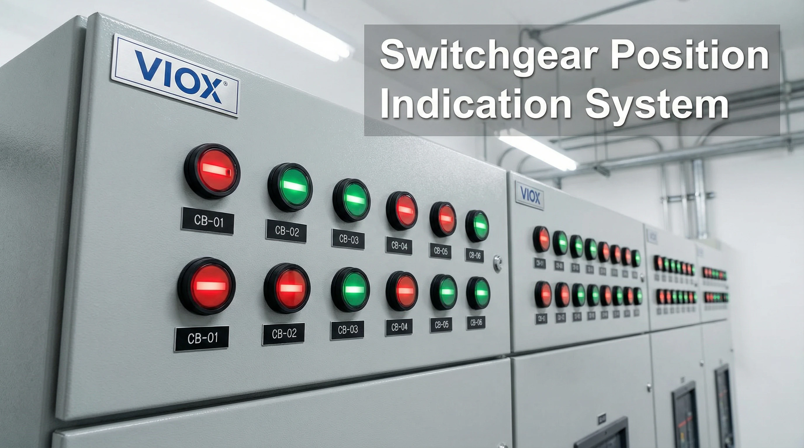
Ve vysokonapěťové rozvodně sleduje elektroinženýr desítky jističů a odpojovačů rozmístěných na několika panelech. Na první pohled dokáže okamžitě identifikovat stav každé kritické komponenty – ne kontrolou digitálních displejů nebo nahlížením do schémat, ale pozorováním jednoduchých červených a zelených světel umístěných na každém panelu. Když jistič neočekávaně vypadne, červený semaforový indikátor okamžitě upoutá její pozornost na místo problému, což umožňuje rychlou reakci dříve, než se drobná porucha rozšíří do výpadku v celém zařízení.
Toto je základní funkce semaforový indikátor—poskytování okamžitých, všeobecně srozumitelných vizuálních informací o stavu, které umožňují informovaná rozhodnutí a rychlé zásahy v elektrických instalacích. Ať už jste elektroinženýr navrhující ovládací panely, výrobce panelů montující rozvaděče nebo údržbář odstraňující problémy s elektrickými systémy, porozumění semaforovým indikátorům je zásadní pro vytváření spolehlivých, bezpečných a předpisům vyhovujících instalací.
V této komplexní příručce zjistíte, co přesně jsou semaforové indikátory montované na panel, jak se liší od ostatních vizuálních signalizačních zařízení, jaké typy jsou k dispozici pro různé aplikace, mezinárodní standardy barevného kódování (IEC 60073), klíčové aplikace v rozvaděčích a ovládacích panelech, kritické technické specifikace, správné postupy instalace a zapojení a jak vybrat správný semaforový indikátor pro vaše specifické požadavky. Na konci budete mít znalosti k tomu, abyste mohli s jistotou specifikovat, instalovat a udržovat tyto základní komponenty elektrických panelů.
Co je semaforový indikátor?
A semaforový indikátor je vizuální signalizační zařízení montované na panel, které se používá v elektrických ovládacích panelech, rozvaděčích a rozvodných deskách k poskytování okamžité indikace stavu jističů, odpojovačů, motorů a dalších elektrických zařízení. Zařízení se skládá z jednoho nebo více LED světelných prvků umístěných v kompaktním válcovém těle, které se montuje skrz standardní otvor v panelu, obvykle o průměru 22 mm nebo 30 mm.
Termín “semafor” pochází z řeckých slov “sema” (znamení) a “phoros” (nosič), což doslova znamená “nosič znamení”. V aplikacích elektroinženýrství slouží semaforové indikátory jako standardizované nástroje vizuální komunikace, které okamžitě sdělují stav zařízení – červené světlo univerzálně indikuje stav “otevřeno” nebo “vypnuto”, zatímco zelené signalizuje “zavřeno” nebo “zapnuto”, bez ohledu na jazyk nebo technické znalosti.
Rozlišení semaforových indikátorů od signálních sloupů
Je důležité objasnit terminologii. Zatímco někteří výrobci používají termín “semaforový indikátor” k popisu více segmentových stohovatelných sloupových světel (nazývaných také signální sloupky nebo stohovací světla), tato příručka se zaměřuje na indikátory stavu montované na panel – kompaktní zařízení s jednou jednotkou instalovaná přímo do čelních desek ovládacího panelu pro okamžité sledování zařízení.
Semaforové indikátory montované na panel mají tyto vlastnosti:
- Pevná instalace v elektrických panelech pomocí standardních montážních otvorů
- Kompaktní provedení (obvykle průměr 22–30 mm)
- Jednobarevné, dvoubarevné nebo vícebarevné LED prvky
- Přímé zapojení do řídicích obvodů
- Primární funkce: indikace stavu jednotlivých zařízení
Signální sloupová světla (někdy také nazývané semaforové indikátory) mají tyto vlastnosti:
- Instalace na sloup nebo na stroj
- Stohovatelná konstrukce s více segmenty (průměr 60–100 mm)
- Viditelné v rozsáhlých prostorách zařízení
- Primární funkce: komunikace stavu stroje v celé oblasti
Tento článek se zabývá semaforovými indikátory montovanými na panel – základními komponentami, které se nacházejí prakticky v každém elektrickém ovládacím panelu a rozvaděči.
Základní komponenty
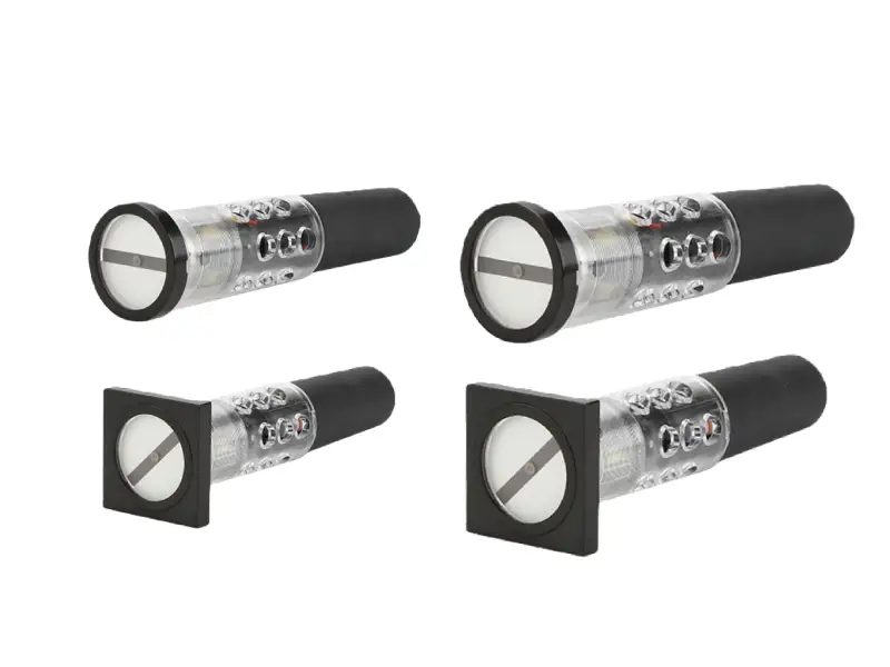
Typický semaforový indikátor montovaný na panel se skládá z:
LED světelný modul: Zdroj osvětlení, obvykle vysoce svítivé LED pole v jedné nebo více barvách (červená, zelená, žlutá, modrá, bílá). Moderní LED diody nabízejí životnost 50 000+ hodin, nízkou spotřebu energie (obvykle 20–100 mA) a okamžitou odezvu zapnutí/vypnutí.
čočka: Průhledná nebo barevná polykarbonátová nebo akrylová čočka, která chrání LED prvky a zároveň zajišťuje optimální distribuci světla. Konstrukce čočky může být plochá, kopulovitá nebo fasetovaná v závislosti na požadavcích na pozorovací úhel.
Tělo pouzdra: Válcové plastové nebo kovové tělo (obvykle o průměru 22,3 mm nebo 30,5 mm), které tvoří hlavní konstrukci. Mezi materiály patří polykarbonát, nylon nebo kovové slitiny vybrané pro trvanlivost a odolnost vůči prostředí.
Montážní komponenty: Tělo se závitem a zajišťovací maticí, které upíná indikátor do otvoru v panelu. Některé konstrukce používají bajonetové úchyty pro instalaci bez použití nářadí.
Připojení svorek: Šroubové svorky, pájecí svorky nebo předem zapojené vodiče (obvykle vodiče 22–26 AWG) pro elektrické připojení k řídicím obvodům.
Obvod rezistoru/budicího obvodu: Interní rezistory omezující proud nebo obvody budiče LED, které umožňují přímé připojení ke společným řídicím napětím (24 V DC, 110 V AC, 220 V AC) bez externích komponent.
Primární Aplikace
Semaforové indikátory montované na panel slouží ke kritickým funkcím v:
Indikace polohy jističe: Dvoubarevné indikátory červená/zelená ukazují stav jističe otevřeno/zavřeno v rozvaděčích a rozvodných panelech, což operátorům umožňuje ověřit spínací operace a okamžitě identifikovat vypnuté jističe.
Centra řízení motorů (MCC): Indikátory zobrazují stav chodu motoru, stavy přetížení a výstrahy poruch pro jednotlivé spouštěče motoru.
Ovládací panely: Univerzální indikace stavu pro jakýkoli řídicí obvod – polohy ventilů, provoz čerpadel, poplachové stavy, stavy procesu nebo dostupnost zařízení.
Rozvaděče a rozvodné desky: Vizuální potvrzení stavu napájení, napájení sběrnice a stavů ochranných zařízení.
Průmyslové řídicí systémy: Stavové displeje řízené PLC pro automatizované procesy, které se integrují s řídicí logikou a poskytují vizuální zpětnou vazbu v reálném čase.
Typy semaforových indikátorů
Semaforové indikátory montované na panel se dodávají v různých konfiguracích, aby vyhovovaly různým požadavkům na monitorování, konstrukcím panelů a architekturám řídicích obvodů. Pochopení těchto variant vám pomůže vybrat optimální indikátor pro vaši konkrétní aplikaci.
Klasifikace podle konfigurace barev
Jednobarevné indikátory: Nejjednodušší konfigurace s jednou barvou LED na jednotku. Ty vyžadují jeden indikátor pro každý stav, který potřebujete sledovat. Mezi běžné aplikace patří:
- Individuální indikace alarmu (červená pro stav poruchy)
- Potvrzení zapnutí (zelená pro napájení)
- Dokončení kroku procesu (modrá pro dokončeno)
Jednobarevné indikátory nabízejí nejnižší cenu za jednotku a nejjednodušší zapojení, ale vyžadují více místa na panelu při sledování více stavů pro jedno zařízení.
Dvoubarevné indikátory: Mají dvě barvy LED v jednom pouzdře, obvykle červenou a zelenou. Toto je nejoblíbenější konfigurace pro rozvaděče a aplikace ovládacích panelů, zejména pro indikaci polohy jističe. Tyto dvě barvy fungují nezávisle – když svítí červená, jistič je otevřený; když svítí zelená, jistič je zavřený. Některé konstrukce umožňují současné osvětlení obou barev pro specifické potřeby indikace (i když je to v elektrických aplikacích méně běžné kvůli potenciální nejednoznačnosti).
Dvoubarevné semaforové indikátory šetří značné místo na panelu ve srovnání se dvěma jednobarevnými jednotkami a poskytují intuitivní indikaci stavu, která je v souladu s univerzálními barevnými konvencemi.
Vícebarevné (RGB) indikátory: Pokročilé indikátory s červenými, zelenými a modrými LED pro flexibilní zobrazení stavu. Používají se v systémech řízených PLC, které vyžadují více provozních stavů. Složitější a nákladnější než dvoubarevné varianty.
Klasifikace podle technologie světelného zdroje
LED (Light Emitting Diode): Současný průmyslový standard, LED semaforové indikátory nabízejí:
- Životnost 50 000–100 000 hodin (5–11 let nepřetržitého provozu)
- Nízká spotřeba energie (obvykle 20–100 mA v závislosti na velikosti a jasu)
- Okamžitá odezva zapnutí/vypnutí bez doby zahřívání
- Vynikající odolnost proti vibracím a nárazům
- Široký rozsah provozních teplot (-40 °C až +85 °C pro kvalitní jednotky)
- Stálá barva po celou dobu životnosti
- Dostupnost v ultra-jasných variantách pro prostředí s vysokým okolním osvětlením
Semaforové indikátory VIOX LED využívají LED čipy prémiové kvality s konzistentními specifikacemi vlnové délky, což zajišťuje spolehlivé rozpoznávání barev a rovnoměrný jas napříč výrobními šaržemi.
Neon: Neonové indikátory, kdysi běžné pro AC obvody, se postupně přestávají používat. Nabízejí střední životnost, ale omezené možnosti barev a křehkost.
Montáž 22 mm: Nejběžnější standard, vyžadující výřez v panelu 22,3 mm. Odpovídá normám IEC 60947-5-1 pro kontrolky a tlačítka.
Zadní montáž se šroubovými svorkami: Standardní konfigurace se závitovou maticí zajišťující zespodu.
Alternativní montáže: Konfigurace s pájecími svorkami, zásuvné patice nebo zacvakávací konfigurace pro specifické aplikace.
Stabilní (nepřetržité): Indikátor zůstává trvale rozsvícený, když je pod napětím. Toto je standardní režim pro indikaci stavu – zařízení v chodu, přítomnost napájení, otevřený ventil atd.
Otřepy: Světlo střídavě přechází mezi stavy zapnuto a vypnuto, čímž přitahuje více pozornosti než stabilní osvětlení. Blikání se obvykle používá pro:
- Alarmové nebo chybové stavy vyžadující potvrzení
- Přechodné stavy (spouštění zařízení, přechod procesu)
- Varování, která předcházejí automatickým akcím
Blikání lze dosáhnout pomocí externího ovládání (výstup PLC, blikací relé) nebo pomocí indikátorů s integrovanými obvody blikání. Frekvence blikání se obvykle pohybuje od 0,5 Hz (pomalé, jednou za dvě sekundy) do 2 Hz (rychlé, dvakrát za sekundu).
Barevné standardy a významy IEC
Standardizované barevné kódování zajišťuje konzistentní interpretaci semaforových indikátorů napříč průmyslovými odvětvími, zeměmi a jazyky. Mezinárodní elektrotechnická komise (IEC) stanovuje tyto normy prostřednictvím IEC 60073, která definuje základní principy pro indikátory a akční členy.
IEC 60073: Barevný standard
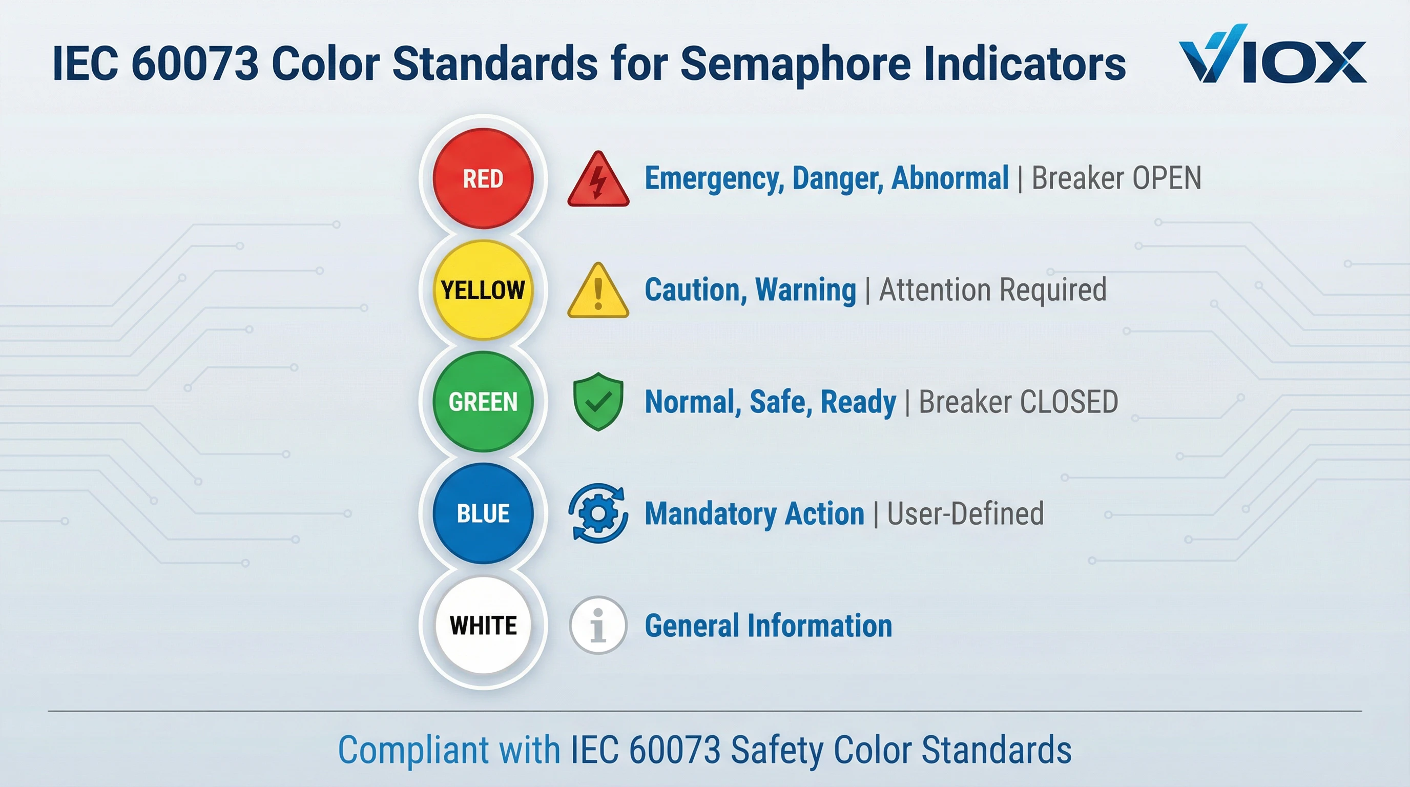
IEC 60073 specifikuje bezpečnostní barvy a principy barevného kódování pro rozhraní člověk-stroj. Pro semaforové indikátory v elektrických aplikacích norma definuje:
Červená: Nouze, Nebezpečí, Abnormální stav
- Jistič otevřený (odpojený, bez napětí)
- Chybový nebo alarmový stav
- Zařízení zastaveno nebo nedostupné
- Vypnuté ochranné zařízení
- Nebezpečný stav vyžadující pozornost
V aplikacích rozváděčů červená konvenčně indikuje “otevřenou” polohu jističe – žádný tok proudu, obvod bez napětí.
Zelená: Normální, Bezpečný, Připravený
- Jistič zavřený (připojený, pod napětím)
- Zařízení běží normálně
- Systém připraven k provozu
- Bezpečné provozní podmínky
- Proces probíhá podle návrhu
V aplikacích rozváděčů zelená indikuje “zavřenou” polohu jističe – proud teče, obvod je pod napětím a funkční.
Žlutá/Oranžová: Upozornění, Varování, Abnormální
- Parametry se blíží limitům
- Brzy bude vyžadována údržba
- Vyžadována pozornost obsluhy
- Přechodný nebo pohotovostní stav
- Odchylka kvality nebo výkonu
Žlutá slouží jako mezilehlé varování – ne nouzové, ale vyžadující monitorování nebo zásah, aby se zabránilo eskalaci.
Modrá: Povinná akce, Uživatelsky definované
- Konkrétně vyžadována akce obsluhy
- Potřeba příkazu reset
- Krok ručního zásahu
- Význam specifický pro aplikaci (musí být zdokumentován)
Význam modré je uživatelsky definován s omezením, že musí indikovat požadovanou akci.
Bílá/Čirá: Obecné informace
- Nekritické informace o stavu
- Doplňková indikace
- Plánované zastavení
- Obecné systémové zprávy
Bílá poskytuje flexibilitu pro signalizaci specifickou pro aplikaci bez předdefinovaných bezpečnostních důsledků.
Aplikace na rozváděče
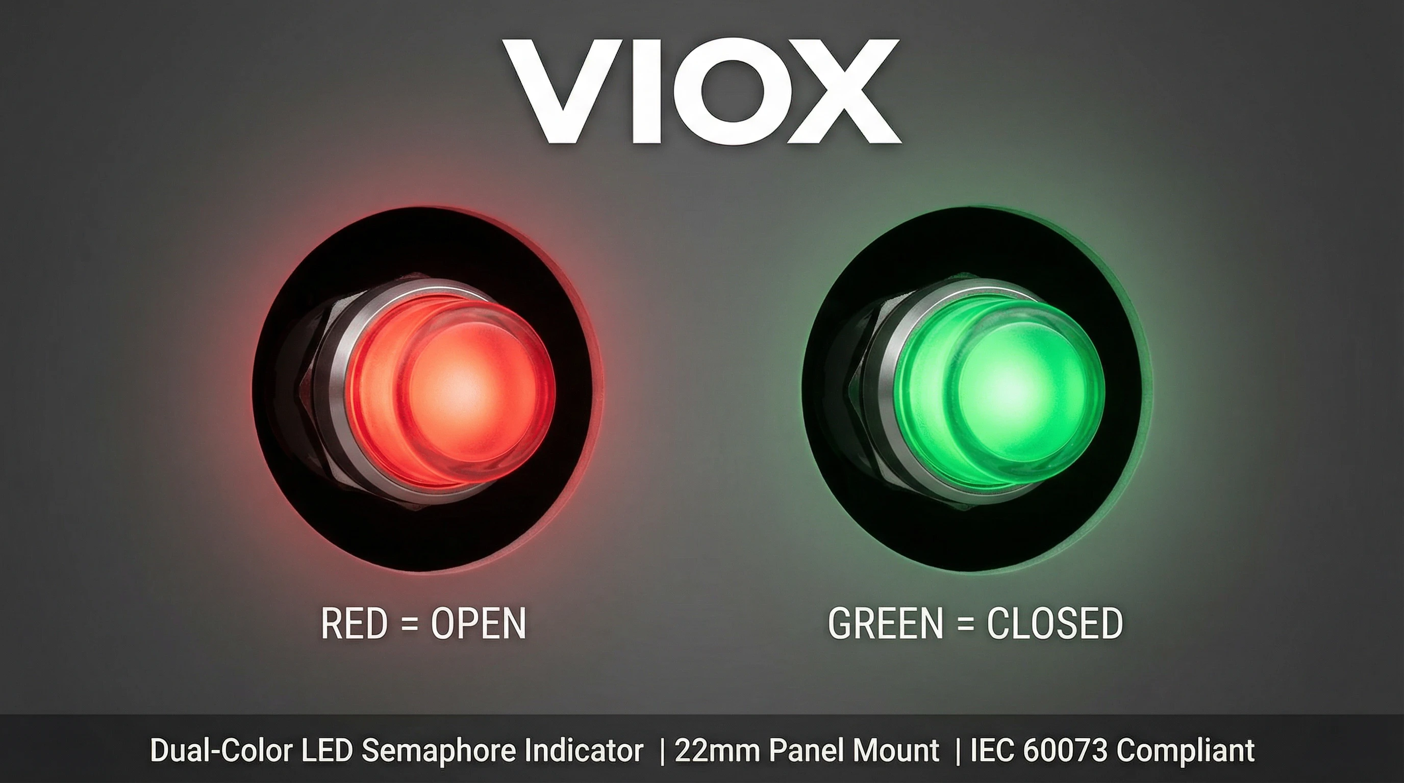
Pro indikaci polohy jističe – nejběžnější aplikace dvoubarevných semaforových indikátorů – je standardní postup:
- Červená = Otevřeno (kontakty jističe otevřené, žádný tok proudu)
- Zelená = Zavřeno (kontakty jističe zavřené, protéká proud)
To odpovídá intuitivním bezpečnostním konvencím: červená (stop, nebezpečí) pro stav bez napětí, zelená (vpřed, bezpečno) pro normální provozní stav. Některá zařízení používají alternativní konvence (červená = pod napětím jako varování), ale standard červená-otevřeno/zelená-zavřeno je nejrozšířenější a doporučuje se pro konzistenci.
Regionální aspekty
Zatímco IEC 60073 poskytuje mezinárodní standardizaci, ověřte si veškeré regionální požadavky:
- Severní Amerika: Odpovídá IEC 60073, s dodatečnými pokyny od ANSI Z535 a UL 508
- Evropa: Striktní dodržování IEC 60073 nařízené směrnicemi pro označení CE
- Asie a Tichomoří: Většina zemí přijímá IEC 60073 jako národní standard (normy GB, JIS, KS)
Udržujte konzistentní významy barev napříč všemi zařízeními v rámci provozu, abyste předešli zmatení obsluhy, i když normy umožňují flexibilitu.
Centra řízení motorů (MCC)
Každý spouštěč motoru v MCC obvykle obsahuje semaforové indikátory pro:
- Stav chodu motoru (zelená)
- Stav vypnutí při přetížení (červená)
- Poruchy řídicího obvodu (žlutá)
- Indikace lokálního/vzdáleného režimu (modrá nebo bílá)
Indikátory umožňují pracovníkům údržby rychle posoudit stav motoru napříč desítkami napáječů bez přístupu do jednotlivých komor spouštěče.
Průmyslové řídicí panely
Systémy řízené PLC používají semaforové indikátory pro:
- Dokončení kroku procesu
- Potvrzení polohy ventilu
- Stav provozu čerpadla
- Varování o hladině v nádrži
- Indikátory počtu výroby
- Upozornění na stav kvality
Indikátory poskytují kritickou zálohu displejů HMI a zůstávají viditelné během selhání obrazovky nebo navigace na jiné stránky.
Rozvaděče a rozvodné desky
V hlavních a podružných rozvaděčích semaforové indikátory zobrazují:
- Stav příchozího napájení
- Napájení sekce sběrnice
- Stav napájecího obvodu
- Detekce zemního spojení
- Dostupnost záložního generátoru
Elektrické systémy budov
Elektrické místnosti v budově používají indikátory pro:
- Stav hlavního jističe
- Indikace připravenosti nouzového napájecího systému
- Stav řídicí jednotky požárního čerpadla
- Monitorování kritických obvodů
- Indikace polohy přepínače
Specializované aplikace
VIOX dodává semaforové indikátory pro náročná prostředí, včetně:
- Zařízení pro ropu a plyn (certifikace pro nebezpečné prostory)
- Námořní a pobřežní instalace (odolnost proti korozi)
- Distribuce energie v datových centrech (požadavky na vysokou spolehlivost)
- Železniční signalizační systémy (schválení specifická pro železnici)
- Instalace obnovitelné energie (široký rozsah teplot, odolnost proti UV záření)
Technické specifikace
Výběr správného semaforového indikátoru vyžaduje pochopení klíčových specifikací:
Jmenovité hodnoty napětí
24V DC: Nejběžnější napětí v průmyslových řídicích systémech. Přímé připojení k výstupům PLC, řídicím relé a 24V DC řídicím obvodům. LED indikátory při 24V obvykle odebírají 20-30mA.
110-120V AC: Standard v severoamerických řídicích obvodech. Indikátory obsahují interní rezistory/budiče pro přímé připojení AC.
220-240 V AC: Běžné v evropských a mezinárodních instalacích. Nezbytné pro zařízení splňující požadavky CE.
12V stejnosměrného proudu: Používá se v automobilovém průmyslu, mobilních zařízeních a nízkonapěťových systémech.
Modely s více napětími: Některé indikátory VIOX akceptují široké rozsahy napětí (12-240V AC/DC), což zjednodušuje inventář a umožňuje globální nasazení.
Specifikace montáže
Průměr výřezu panelu: Nejkritičtější rozměr. Běžné standardy:
- 22,3 mm (nominálně 22 mm) – Nejběžnější, standard IEC 60947-5-1
- 30,5 mm (nominálně 30 mm) – Větší formát pro lepší viditelnost
Ověřte si přesný průměr výřezu a toleranci z datových listů výrobce.
Rozsah tloušťky panelu: Obvykle se hodí pro panely o tloušťce 1-10 mm. Silnější panely mohou vyžadovat modely s prodlouženým tělem nebo distanční podložky.
Montážní hloubka za panelem: Rozměr od přední strany panelu k zadní svorce, obvykle 40-60 mm. Kritické pro mělké panely nebo těsné rozestupy.
Specifikace LED
Svítivost: 20-50 mcd (standardní), 100-300 mcd (vysoký jas), 500+ mcd (venkovní/sluneční světlo).
Životnost LED: 50 000–100 000 hodin u kvalitních indikátorů.
Vlnová délka barvy: Přesné specifikace zajišťují konzistentní barvu – červená: 620–630 nm, zelená: 520–530 nm, žlutá: 585–595 nm.
Hodnocení životního prostředí
Stupeň krytí IP: IP65 (standardní ovládací panely) nebo IP67 (venkovní/omyvatelné prostředí).
Provozní teplota: -25 °C až +70 °C standardně; -40 °C až +85 °C rozšířený rozsah pro náročná prostředí.
Certifikace
UL 508 (Severní Amerika), Označení CE (Evropa), IEC 60947-5-1 (Mezinárodní), CCC (Čína). Společnost VIOX udržuje komplexní globální certifikace zajišťující celosvětovou shodu.
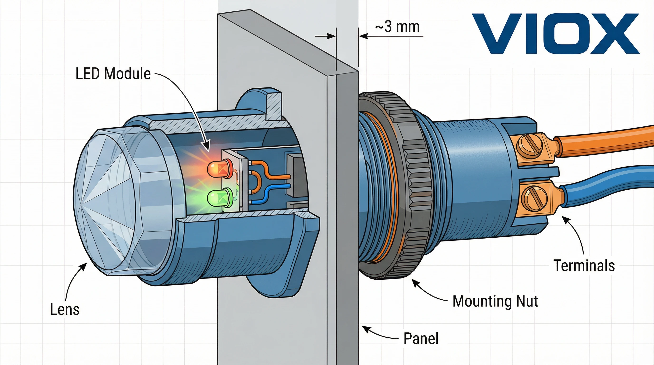
Instalace a zapojení
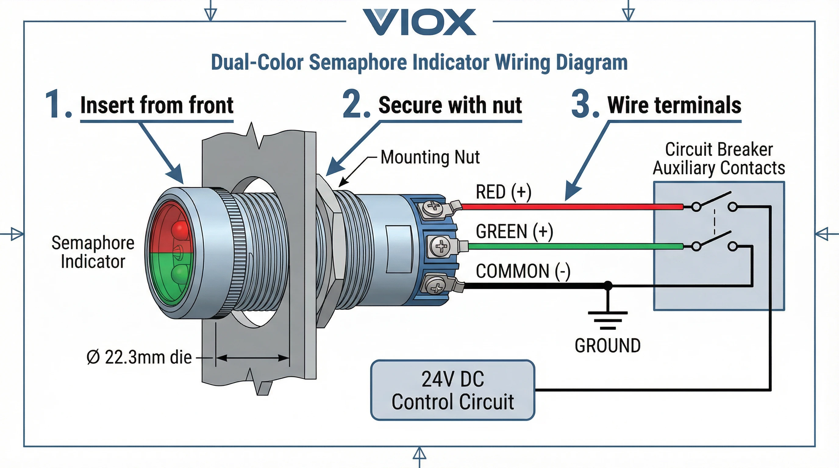
Montáž na panel
- Vyvrtejte otvor o stanoveném průměru (22,3 mm nebo 30,5 mm) v panelu. Odstraňte otřepy z hran.
- Vložte indikátor skrz výřez zepředu.
- Našroubujte upevňovací matici zezadu. Utáhněte rukou a poté o 1/4 otáčky.
- Ověřte lícování.
Konfigurace zapojení
Jednobarevný: Dva terminály (+) a (-). Připojte (+) ke zdroji ovládání, (-) k uzemnění.
Dvoubarevný (společná katoda): Tři terminály – červený (+), zelený (+), společný (-). Uzemněte společný, napájejte jednotlivé barevné vodiče.
Typické zapojení rozvaděče: Červený (+) k pomocnému kontaktu “a” jističe (sepne, když se jistič otevře), zelený (+) ke kontaktu “b” (sepne, když se jistič zavře), společný (-) k uzemnění.
Bezpečnost
- Ověřte, zda napětí odpovídá obvodu
- Použijte správné jištění a průřez vodiče (18–22 AWG)
- Před instalací odpojte napájení
- Dodržujte předpisy NEC/IEC
Průvodce výběrem
Výběr správného semaforového indikátoru zahrnuje sladění specifikací s požadavky aplikace.
1. Určete požadované barvy
- Jeden stav = jednobarevný
- Poloha jističe = dvoubarevný (červená/zelená)
- Více stavů = zvažte více jednobarevných nebo vícebarevných indikátorů
2. Vyberte jmenovité napětí
- Slaďte s napětím stávajícího ovládacího obvodu (typicky 24 V DC, 110 V AC nebo 220 V AC)
- Zvažte více napěťové modely pro flexibilitu
3. Ověřte montážní rozměry
- Zkontrolujte dostupný prostor na panelu
- Potvrďte přizpůsobení tloušťce panelu
- Ověřte zadní prostor pro terminály a zapojení
4. Posuďte podmínky prostředí
- Vnitřní kontrolované prostředí = standardní IP65
- Venkovní nebo náročné prostředí = IP67
- Extrémní teploty = specifikujte rozšířený teplotní rozsah
5. Potvrďte certifikace
- Severní Amerika = seznam UL 508
- Evropa = označení CE
- Specializovaná odvětví = schválení specifická pro dané odvětví
6. Zvažte kvalitativní ukazatele
- Specifikace životnosti LED (50 000+ hodin)
- Pověst a podpora výrobce
- Záruční podmínky (typicky 2–3 roky u kvalitních produktů)
- Dostupnost náhradních dílů
Výhoda VIOX: Semaforové indikátory VIOX kombinují prémiovou technologii LED, komplexní certifikace a vynikající výrobu. Díky přesným barevným specifikacím, robustní konstrukci a globální shodě poskytují indikátory VIOX spolehlivý výkon v náročných aplikacích. Náš tým technické podpory pomáhá s výběrem produktů, vlastními konfiguracemi a pokyny pro integraci.
Závěr
Semaforové indikátory montované na panel jsou základní součástí elektrických řídicích systémů a poskytují okamžitý vizuální stav jističů, motorů a řídicího zařízení. Vývoj technologie LED vytvořil spolehlivá aktiva s dlouhou životností s životností 50 000+ hodin a minimálními požadavky na údržbu.
Standardizace IEC 60073 zajišťuje univerzální interpretaci napříč jazyky a kulturami – červená pro abnormální/otevřený, zelená pro normální/zavřený, žlutá pro varování, modrá pro požadované akce. Tato konzistence zvyšuje bezpečnost a provozní efektivitu globálně.
Při specifikaci semaforových indikátorů slaďte napětí s řídicími obvody, montážní rozměry s konstrukcí panelu, environmentální hodnocení s podmínkami a certifikace s regulačními požadavky. Kvalitní indikátory od výrobců jako VIOX zajišťují spolehlivý výkon, správné certifikace a odbornou technickou podporu.
Jste připraveni specifikovat semaforové indikátory? VIOX nabízí komplexní řešení od standardních konfigurací po vlastní návrhy. Náš inženýrský tým poskytuje desítky let odborných znalostí v oblasti rozvaděčů a ovládacích panelů. Kontaktujte VIOX ještě dnes pro optimální specifikace, podrobnou dokumentaci a kvalitní produkty podpořené komplexní zárukou a pohotovou podporou.
Vyberte si semaforové indikátory VIOX pro jasnost, spolehlivost a klid v elektrických instalacích.
