
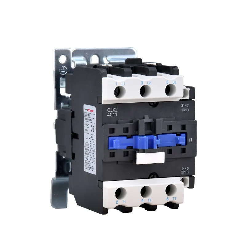
Low-voltage contactors are the workhorses of motor control. Their ability to switch loads rapidly and reliably — with electrical endurance ratings exceeding one million operations — makes them indispensable across industrial automation, HVAC systems, and power distribution. But every switching event has a hidden cost: the transient voltage spike generated when the stykač coil de-energizes.


Why Contactor Coils Generate Voltage Spikes
The coil is the electromagnetic engine of every contactor. When energized, it draws a high inrush current to pull in the armature. When de-energized, it produces a potentially destructive transient voltage surge — and understanding why is the key to selecting the right suppression strategy.
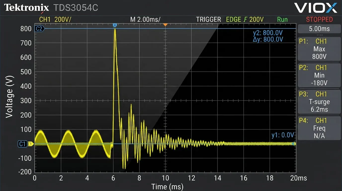
The root cause is self-inductance. At the instant of de-energization the coil current drops rapidly toward zero. According to Lenz’s law, the collapsing magnetic field induces a counter-EMF (back-EMF) across the coil terminals in an attempt to maintain current flow. Because the rate of current change ($di/dt$) is extremely high during a fast disconnect, the resulting voltage spike can reach hundreds or even thousands of volts.
These transient spikes pose two distinct risks. First, they cause component damage — accelerated erosion of kontakty relé, degradation of semiconductor switching devices (transistors, SSRs), and premature coil insulation breakdown. Second, they generate electromagnetic interference (EMI) that couples into nearby signal wiring and disrupts sensitive control electronics such as PLCs, microcontrollers, and communication buses.
To mitigate these effects, four types of surge suppressors are commonly applied across the contactor coil. Each offers a different trade-off between suppression effectiveness, applicable coil type, and impact on contactor release time.
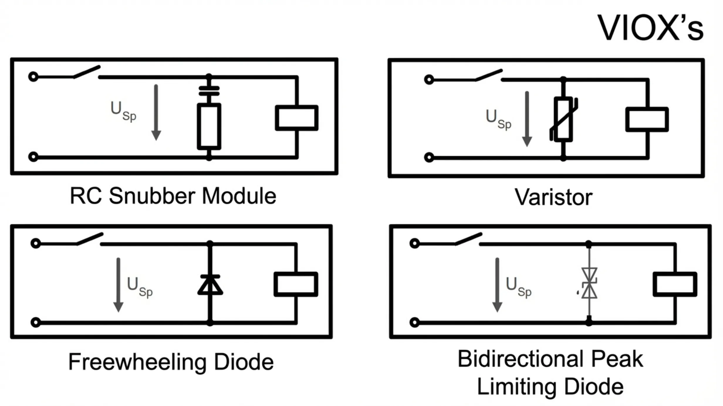
1. RC Snubber Circuit
Na stránkách RC snubber — a resistor and capacitor in series, connected in parallel with the coil — is one of the most widely used suppression methods.
Operating principle. When the coil de-energizes, the induced back-EMF drives current through the snubber network. The capacitor absorbs the transient energy and converts it to stored electric-field energy, effectively clamping the voltage spike to a manageable level. The stored energy is then dissipated as heat through the parallel resistor. Equally important, the resistor provides damping that prevents the capacitor and coil inductance from forming an underdamped LC oscillation, which would otherwise generate a new series of voltage ringing.
Klíčové vlastnosti:
- Applicable coil types: AC and DC
- Voltage clamping level: ≤ 3 × Uc (rated coil voltage)
- Impact on release time: Moderate — typically 1.2× to 2× the normal release time
- Omezení: Not recommended in circuits with high harmonic content, as harmonics can cause excessive heating in the capacitor
The RC snubber is a cost-effective, general-purpose solution. Its main drawback is that the clamping ratio (3× Uc) is the highest of the four options, meaning some residual spike energy still reaches the control circuit.
2. Varistor (MOV)
A metal oxide varistor (MOV) suppresses coil transients through its highly nonlinear voltage–current characteristic. It acts as a voltage-dependent clamping device rather than an energy-absorbing oscillation damper.
Operating principle. Under normal coil voltage the varistor presents a very high impedance — effectively open circuit — and draws negligible leakage current. When the coil de-energizes and the transient voltage exceeds the varistor’s clamping voltage (typically 1.6× to 2× the rated coil voltage), the zinc-oxide grain boundaries avalanche into conduction. The varistor impedance drops by several orders of magnitude, shunting the surge current and clamping the terminal voltage to a safe level. Once the transient subsides, the varistor returns to its high-impedance state.
Klíčové vlastnosti:
- Applicable coil types: AC and DC
- Voltage clamping level: ≤ 2 × Uc
- Impact on release time: Minor — typically 1.1× to 1.5× the normal release time
- Úvaha: Varistors degrade over time with repeated surge absorption events; in high-cycle applications, periodic inspection or replacement may be necessary
The varistor offers better clamping (2× Uc vs. 3× Uc) and less impact on release time than the RC snubber, making it a strong choice for general-purpose contactor protection in both AC and DC circuits.
3. Freewheeling Diode (Flyback Diode)
Na stránkách freewheeling diode — also called a flyback diode or suppression diode — provides the most effective voltage spike suppression of any passive method. It works by giving the coil’s stored magnetic energy a low-impedance current path, eliminating the high-voltage transient at its source.
Operating principle. The diode is connected in reverse-bias across the DC coil terminals. During normal operation it is reverse-biased and carries no current. At the instant of de-energization, the collapsing magnetic field reverses the polarity across the coil, forward-biasing the diode. The coil current continues to circulate through the diode in a closed loop, decaying gradually as the energy is dissipated in the coil’s own DC resistance. Because the current path never opens abruptly, no high $di/dt$ event occurs and therefore no significant voltage spike is generated.
Klíčové vlastnosti:
- Applicable coil types: DC only (a diode’s unidirectional conduction makes it incompatible with AC coils)
- Voltage clamping level: ≈ 0 V — the back-EMF is essentially eliminated
- Impact on release time: Severe — typically 6× to 10× the normal release time
- Kritické omezení: The extended release time means the contactor’s main contacts remain closed much longer after the control signal is removed; this is unacceptable in applications requiring fast de-energization (e.g., emergency stop circuits, reversing contactors)
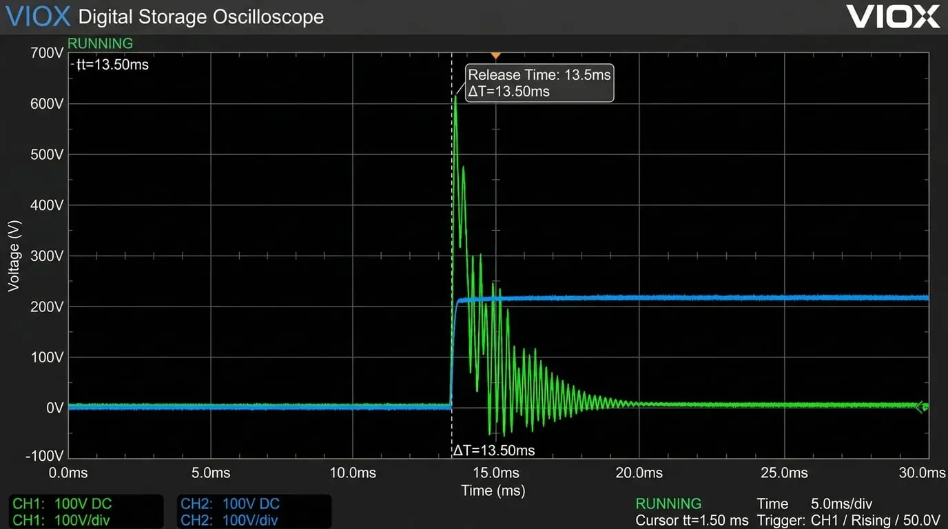
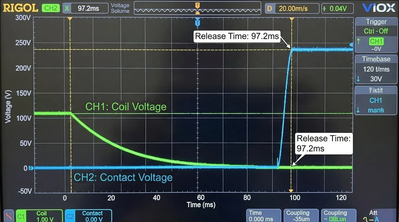
The oscilloscope captures below illustrate the trade-off clearly. Figure 10 shows a DC contactor without a freewheeling diode: the green trace (coil voltage) exhibits a large transient spike, and the release time is 13.5 ms. Figure 11 shows the same contactor with a freewheeling diode installed: the back-EMF is clamped to 0 V, but the release time extends to 97.2 ms — approximately 7× longer.
The freewheeling diode is the best choice when maximum spike suppression is the priority and the extended release time is acceptable — for example, in non-safety-critical DC control circuits where EMI sensitivity is high.
4. Bidirectional TVS Diode
A bidirectional transient voltage suppressor (TVS) diode combines precise voltage clamping with minimal impact on release time, making it arguably the most balanced suppression solution available.
Operating principle. The bidirectional TVS diode is connected across the coil terminals. Under normal operating voltage it presents high impedance and does not affect circuit operation. When the coil de-energizes and the transient voltage — in either polarity — exceeds the TVS breakdown voltage, the device enters avalanche breakdown within nanoseconds. It transitions from high impedance to low impedance, absorbing the surge energy and clamping the terminal voltage to a predictable, safe level determined by its PN junction characteristics. Once the transient passes, the TVS returns to its blocking state.
Klíčové vlastnosti:
- Applicable coil types: AC and DC
- Voltage clamping level: ≤ 2 × Uc
- Impact on release time: Negligible — release timing is essentially unchanged
- Výhoda: The fast response time (sub-nanosecond) and precise clamping voltage make TVS diodes especially effective at protecting sensitive downstream electronics
Critical sizing consideration: Unlike varistors and RC snubbers, TVS diodes have relatively limited surge current capability ($I_{TSM}$) and peak pulse power ratings ($P_{PP}$). The energy stored in a contactor coil at the moment of de-energization is $E = \frac{1}{2}LI^2$, and for large contactors (typically >100 A frame size) with high coil inductance, this energy can easily exceed the single-pulse absorption rating of a standard TVS device — resulting in catastrophic junction failure. Before specifying a TVS diode, always calculate the coil’s stored energy and verify that the selected device’s $P_{PP}$ rating provides adequate margin. A common rule of thumb is to select a TVS with a peak pulse power rating at least 2× to 3× the calculated coil energy. This is one of the most frequently encountered field failure modes: the TVS appears to work during commissioning but fails silently after repeated high-energy switching cycles, leaving the circuit unprotected.
The bidirectional TVS diode is the preferred choice when both effective clamping and uncompromised release time are required — a common requirement in modern automated systems with tight safety and timing constraints.
Comparison and Selection Guide
The table below summarizes the four suppressor types across the key selection criteria.
| Parametr | RC člen | Varistor (MOV) | Volnoběžná dioda | Bidirectional TVS Diode |
|---|---|---|---|---|
| Suppression mechanism | Capacitive energy absorption + resistive dissipation | Nonlinear ZnO grain boundary conduction | Low-impedance DC current recirculation | PN junction avalanche breakdown clamping |
| AC coil compatible | ✅ Ano | ✅ Ano | ❌ Ne | ✅ Ano |
| DC coil compatible | ✅ Ano | ✅ Ano | ✅ Ano | ✅ Ano |
| Voltage clamping level | ≤ 3 × Uc | ≤ 2 × Uc | ≈ 0 V | ≤ 2 × Uc |
| Release time impact | 1.2× – 2× | 1.1× – 1.5× | 6× – 10× | ≈ 1× (negligible) |
| Response speed | Mírná | Rychle | N/A (continuous path) | Very fast (< 1 ns) |
| Typická aplikace | General-purpose, cost-sensitive | General-purpose AC/DC | DC circuits tolerant of slow release | High-performance, timing-critical systems |
Practical Selection Recommendations
For AC coil contactors, the choice narrows to three options since the freewheeling diode is not applicable. If release time is critical — as in safety interlocks or rapid-cycling machinery — the bidirectional TVS diode is the strongest candidate. If cost is the primary concern and moderate clamping is acceptable, the RC snubber is a proven, economical choice. The varistor sits between the two, offering better clamping than the RC snubber with minimal release time penalty.
For DC coil contactors, all four options are available. The freewheeling diode delivers unmatched suppression (0 V back-EMF) but should only be used where the 6× to 10× increase in release time is acceptable. In timing-sensitive DC applications — especially those feeding PLC inputs or communicating with fieldbus systems — the bidirectional TVS diode provides the best overall balance of suppression performance and dynamic response.
In practice, many engineers combine suppressors for defense-in-depth. A common configuration pairs a freewheeling diode with a series Zener diode (or a TVS diode) to limit back-EMF while constraining the release time increase — but that is a topic for a deeper discussion on advanced suppression networks.
For comprehensive guidance on contactor selection and maintenance, see our guides on údržbě průmyslových stykačů a odstraňováním problémů se stykači.
Často kladené otázky (FAQ)
Why does my contactor coil generate voltage spikes when it turns off?
Every contactor coil is an inductor. When the control circuit interrupts the coil current, the collapsing magnetic field generates a counter-EMF (back-EMF) according to Lenz’s law. Because the current drops to zero very quickly, the resulting $di/dt$ is extremely high, producing transient voltage spikes that can reach hundreds or thousands of volts — far exceeding the coil’s rated voltage.
What’s the difference between an RC snubber and a varistor for contactor protection?
An RC snubber absorbs the transient energy in a capacitor and dissipates it through a resistor, clamping the spike to approximately 3× the rated coil voltage. A varistor (MOV) uses its nonlinear resistance to clamp the voltage more tightly — typically to about 2× the rated coil voltage — with less impact on release time. Varistors offer better suppression performance, while RC snubbers are simpler and less expensive.
Why does a freewheeling diode increase contactor release time?
A freewheeling (flyback) diode provides a near-zero-impedance path for the coil current to circulate after de-energization. This eliminates the voltage spike entirely, but the coil current decays very slowly through the diode and the coil’s DC resistance instead of dropping abruptly. As a result, the magnetic force holding the armature persists much longer, and the contactor’s release time increases by 6× to 10× — a critical concern in applications that require fast de-energization such as emergency stop circuits.
Can I use the same surge suppressor for AC and DC contactors?
It depends on the suppressor type. RC snubbers, varistors (MOVs), and bidirectional TVS diodes are compatible with both AC and DC coils. However, freewheeling diodes can only be used with DC coils because they rely on unidirectional conduction — connecting one across an AC coil would short-circuit every negative half-cycle, damaging the diode and the circuit.
How do I choose between a TVS diode and a varistor for contactor surge suppression?
Both clamp the coil’s back-EMF to approximately 2× Uc, but they differ in two important ways. A bidirectional TVS diode offers faster response (sub-nanosecond) and negligible impact on release time, making it ideal for timing-critical and EMI-sensitive applications. A varistor is more tolerant of high-energy surges from large coils and costs less, but it degrades over time with repeated operations. For high-cycle, large-frame contactors, verify that the TVS diode’s peak pulse power rating ($P_{PP}$) exceeds the coil’s stored energy — otherwise, a varistor may be the safer choice.
