
Elektronické spouště v jističe v lisovaném pouzdře (MCCB) mohou selhat při vystavení elektromagnetickému rušení, což způsobuje neočekávané odstávky, které průmyslové provozy stojí tisíce dolarů za hodinu. Tato komplexní příručka zkoumá, jak EMI ovlivňuje elektronické spouště MCCB, základní mechanismy rušení a osvědčené strategie pro zmírnění dopadů, které zajistí spolehlivou ochranu obvodů v elektromagneticky náročných prostředích.
Klíčové poznatky
- Zranitelnost vůči EMI: Elektronické spouště jsou 3-5krát náchylnější k elektromagnetickému rušení než termomagnetické typy kvůli citlivým mikroprocesorovým obvodům
- Režimy selhání: EMI může způsobit nežádoucí vypínání (40 % případů), falešné hodnoty (35 %), nebo úplné zablokování (25 %) u elektronických MCCB
- Kritické frekvence: Většina rušení se vyskytuje v rozsahu 150 kHz až 30 MHz pro vedené EMI a 80 MHz až 1 GHz pro vyzařované EMI
- Dodržování norem: IEC 60947-2 nařizuje testování odolnosti při 10 V/m pro vyzařovaná pole a 10 V pro vedené poruchy
- Dopad na náklady: Nežádoucí vypnutí související s EMI stojí průmyslové provozy 15 000-50 000 dolarů za incident v prostojích a ztracené produkci
Pochopení elektronických spouští MCCB
Elektronické spouště představují významný pokrok v technologii ochrany obvodů, nahrazují tradiční termomagnetické mechanismy systémy založenými na mikroprocesorech. Tato sofistikovaná zařízení nepřetržitě monitorují tok proudu pomocí přesných senzorů a provádějí složité algoritmy, aby určily, kdy je nutný ochranný zásah. Na rozdíl od svých termomagnetických předchůdců, kteří se spoléhají na fyzikální vlastnosti bimetalových pásků a elektromagnetických cívek, elektronické spouště zpracovávají elektrické signály digitálně, což umožňuje programovatelná nastavení, komunikační schopnosti a přesné ochranné charakteristiky.
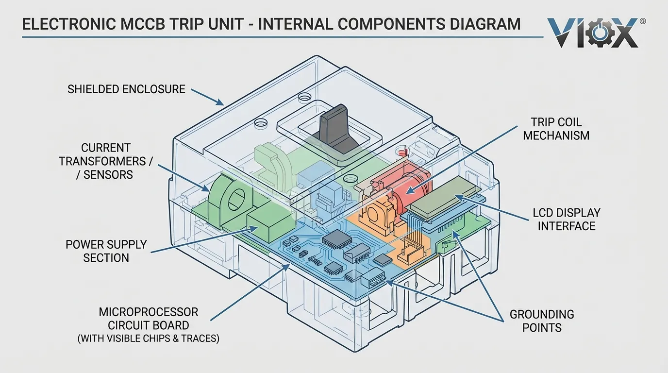
Mezi hlavní komponenty elektronické spouště patří proudové transformátory (CT) nebo Rogowského cívky pro snímání, analogově-digitální převodníky (ADC), mikrokontrolér nebo digitální signálový procesor (DSP), obvody napájecího zdroje a výstupní budiče pro spouštěcí mechanismus. Tato digitální architektura poskytuje vynikající přesnost a flexibilitu, ale zavádí zranitelnost vůči elektromagnetickému rušení, které může narušit normální provoz. Mikroprocesor pracuje s hodinovými frekvencemi typicky v rozsahu od 8 MHz do 100 MHz, s úrovněmi signálu v rozsahu milivoltů až voltů – díky tomu jsou tyto obvody obzvláště náchylné k vnějším elektromagnetickým poruchám.
Zdroje EMI v průmyslovém prostředí
Průmyslové provozy generují intenzivní elektromagnetická pole z mnoha zdrojů pracujících současně. Měniče frekvence (VFD) představují jeden z nejvýznamnějších zdrojů EMI, produkují vysokofrekvenční spínací šum v rozsahu 2-20 kHz základní frekvence s harmonickými zasahujícími do rozsahu MHz. Tyto měniče používají izolované bipolární tranzistory s hradlem (IGBT) nebo MOSFET, které spínají rychlostí 2-20 kHz, čímž vytvářejí strmé napěťové a proudové přechody (dV/dt a dI/dt), které vyzařují elektromagnetickou energii a vedou rušení prostřednictvím napájecích a řídicích kabelů.
Svařovací zařízení generuje obzvláště silné elektromagnetické poruchy, přičemž obloukové svářečky produkují širokopásmový šum od DC do několika MHz a odporové svářečky vytvářejí opakující se vysokoproudé pulzy. Radiofrekvenční (RF) zařízení včetně bezdrátových komunikačních systémů, RFID čteček a průmyslových topných systémů přispívají k vyzařovanému rušení ve specifických frekvenčních pásmech. Elektrické motory, zejména při spouštění a zastavování, produkují přechodná elektromagnetická pole a vedený šum na napájecích vedeních. Spínané napájecí zdroje, které se nacházejí v moderních provozech v počítačích, řídicích jednotkách a LED osvětlení, generují vysokofrekvenční spínací šum typicky v rozsahu 50 kHz až 2 MHz.
Údery blesku a elektrostatické výboje (ESD) vytvářejí přechodné elektromagnetické pulzy s extrémně rychlými náběžnými hranami a širokým frekvenčním obsahem. Dokonce i blízká elektrická vedení přenášející vysoké proudy mohou indukovat rušení prostřednictvím magnetické vazby. Kumulativní efekt mnoha zdrojů EMI pracujících současně vytváří komplexní elektromagnetické prostředí, kde elektronické spouště musí udržovat spolehlivý provoz.
Mechanismus vazby EMI do elektronických spouští
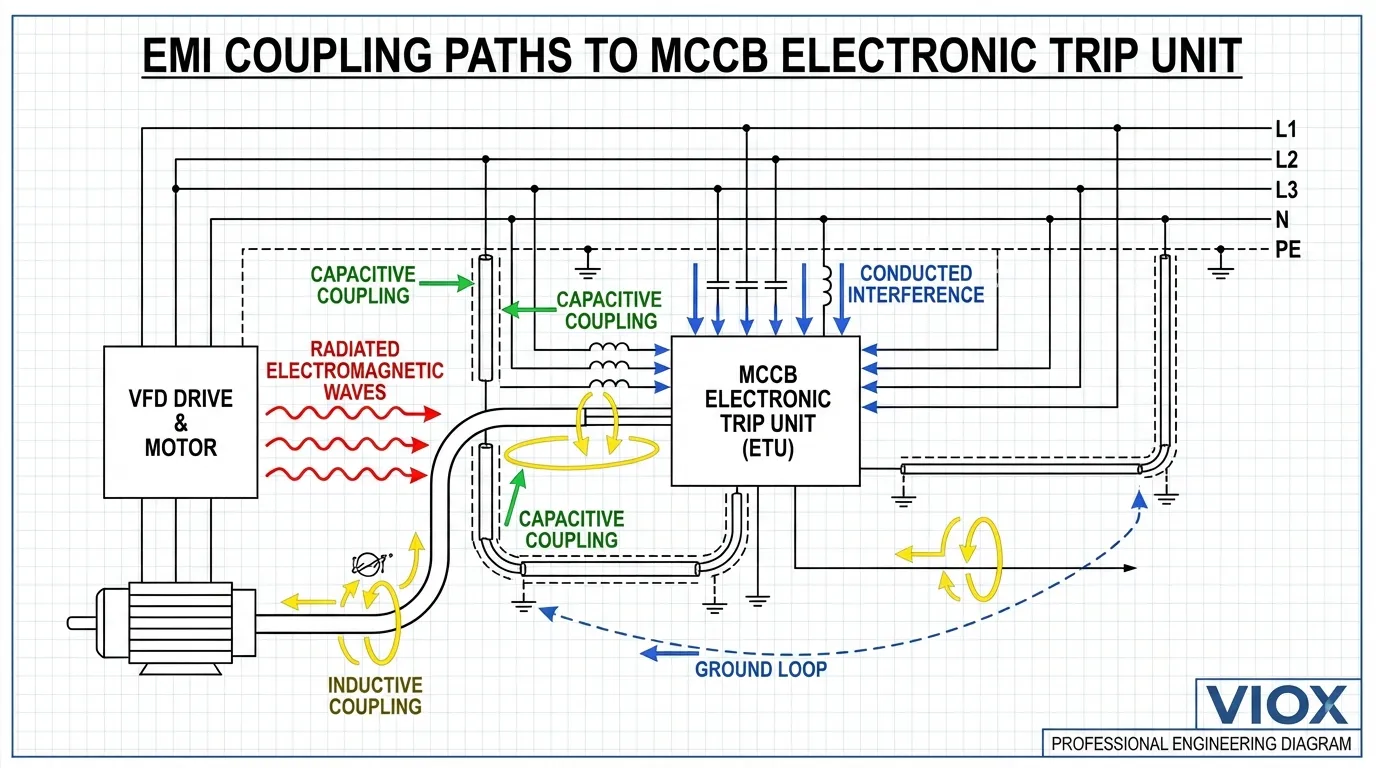
Elektromagnetické rušení se dostává do obvodů elektronické spouště prostřednictvím čtyř primárních mechanismů vazby, z nichž každý má odlišné charakteristiky a požadavky na zmírnění dopadů. Vedená vazba nastává, když se rušení šíří po napájecích vedeních, řídicích kabelech nebo komunikační kabeláži přímo do obvodů spouště. Vysokofrekvenční šum na napájecím zdroji může obejít filtrační kondenzátory a dostat se do citlivých analogových a digitálních obvodů, zatímco proudy se společným módem na kabelech se mohou vázat do signálových cest prostřednictvím parazitní kapacity.
Vyzařovaná vazba nastává, když se elektromagnetické vlny šíří vzduchem a indukují napětí v obvodových stopách, vývodech komponent nebo kabelových smyčkách uvnitř spouště. Účinnost vyzařované vazby závisí na frekvenci, intenzitě pole a fyzických rozměrech přijímacích struktur. Obvodové stopy nebo drátové smyčky, které jsou významnou částí vlnové délky (typicky λ/10 nebo větší), se stávají účinnými anténami pro příjem rušení. Například při 100 MHz se λ/10 rovná přibližně 30 cm, což znamená, že mnoho vnitřních struktur může účinně přijímat vyzařované EMI.
Kapacitní vazba (vazba elektrického pole) nastává, když časově proměnné elektrické pole indukuje posuvné proudy v blízkých vodičích. Tento mechanismus je nejvýznamnější při vyšších frekvencích a když jsou obvody s vysokou impedancí umístěny v blízkosti zdrojů rychle se měnících napětí. Vazební kapacita mezi zdrojem rušení a obvodem oběti může být pouze několik pikofaradů, ale při vysokých frekvencích to poskytuje cestu s nízkou impedancí pro rušení. Indukční vazba (vazba magnetického pole) nastává, když časově proměnné magnetické pole indukuje napětí ve vodivých smyčkách podle Faradayova zákona. Indukované napětí je úměrné rychlosti změny magnetického toku, ploše smyčky a počtu závitů, což činí tento mechanismus obzvláště problematickým pro obvody s velkými plochami smyček nebo když jsou umístěny v blízkosti vysokoproudých vodičů.
Relativní důležitost těchto mechanismů vazby se mění s frekvencí. Pod 10 MHz obvykle dominují vedená a indukční vazba, zatímco nad 30 MHz se stávají významnějšími vyzařovaná a kapacitní vazba. V praxi často existuje více cest vazby současně a dominantní mechanismus se může měnit v závislosti na specifické konfiguraci instalace a charakteristikách zdroje EMI.
Analýza dopadu: Jak EMI ovlivňuje výkon spouště
Elektronické spouště MCCB vykazují několik odlišných režimů selhání, když jsou vystaveny elektromagnetickému rušení, z nichž každý má různé provozní důsledky a rizikové profily. Nepříjemné zakopnutí představuje nejběžnější selhání způsobené EMI, které představuje přibližně 40 % hlášených incidentů. V tomto scénáři se rušení váže do obvodů snímání nebo zpracování proudu a vytváří falešné signály, které mikroprocesor interpretuje jako nadproudový stav. Spoušť provede svou ochrannou funkci a otevře jistič, i když neexistuje žádná skutečná porucha. To způsobuje neočekávané odstávky, ztráty produkce a narušení důvěry v ochranný systém.
Falešné hodnoty a chyby měření nastávají, když EMI poškodí proces analogově-digitální konverze nebo naruší obvody snímání proudu. Spoušť může zobrazovat nesprávné hodnoty proudu, zaznamenávat chybné údaje nebo provádět ochranná rozhodnutí na základě poškozených měření. I když to nemusí způsobit okamžité vypnutí, ohrožuje to přesnost koordinace ochrany a může vést buď k selhání vypnutí během skutečných poruch, nebo ke zpožděnému vypnutí, které umožňuje poškození zařízení. Studie naznačují, že tento režim selhání představuje přibližně 35 % problémů souvisejících s EMI.
Úplné zablokování nebo porucha představuje nejzávažnější dopad, kdy elektromagnetické rušení naruší provoz mikroprocesoru do té míry, že spoušť přestane reagovat. Procesor může vstoupit do nedefinovaného stavu, zacyklit se v nekonečné smyčce nebo zaznamenat poškození paměti. V tomto stavu nemusí spoušť poskytnout ochranu během skutečné poruchy – nebezpečná situace, která porušuje základní požadavek na bezpečný provoz při poruše. Tento režim selhání představuje přibližně 25 % hlášených incidentů EMI a představuje největší bezpečnostní riziko.
Selhání komunikace ovlivňují spouště s digitálními komunikačními schopnostmi (Modbus, Profibus, Ethernet/IP atd.). EMI může poškodit datové pakety, způsobit vypršení časových limitů komunikace nebo zcela zakázat komunikační rozhraní. I když to nemusí přímo ovlivnit ochrannou funkci, zabraňuje to vzdálenému monitorování, koordinaci s jinými ochrannými zařízeními a integraci se systémy správy budov. Frekvence a závažnost těchto dopadů závisí na mnoha faktorech, včetně intenzity pole, frekvenčního obsahu, účinnosti cesty vazby a inherentní odolnosti specifické spouště.
Srovnání: Elektronické vs. termomagnetické spouště
| Charakteristický | Elektronické Výlet Jednotek | Termomagnetické spouště | Výhoda EMI |
|---|---|---|---|
| Náchylnost k EMI | Vysoká (citlivé mikroprocesorové obvody) | Nízká (pasivní mechanické komponenty) | Termomagnetická |
| Princip fungování | Zpracování digitálního signálu, ADC konverze | Fyzikální vlastnosti (teplo, magnetická síla) | Termomagnetická |
| Typická úroveň odolnosti | 10 V/m (minimum IEC 60947-2) | Inherentně odolná vůči většině EMI | Termomagnetická |
| Zranitelný frekvenční rozsah | 150 kHz – 1 GHz | Minimální zranitelnost | Termomagnetická |
| Riziko rušivého vybavení | Střední až vysoká v prostředích s EMI | Velmi nízké | Termomagnetická |
| Přesnost ochrany | ±1-2 % nastavení | ±10-20 % nastavení | Elektronická |
| Nastavitelnost | Plně programovatelná nastavení | Pevné nebo omezené nastavení | Elektronická |
| Komunikační schopnost | K dispozici digitální protokoly | Žádný | Elektronická |
| Tolerance k prostředí | Vyžaduje zmírnění dopadů EMI v náročných prostředích | Funguje spolehlivě bez zvláštních opatření | Termomagnetická |
| Náklady | Vyšší počáteční náklady | Nižší počáteční náklady | Termomagnetická |
| Údržba | Možné aktualizace firmwaru, autodiagnostika | Žádná údržba softwaru | Smíšené |
Toto srovnání odhaluje zásadní kompromis mezi pokročilou funkčností a odolností proti EMI. Elektronické spouštěcí jednotky poskytují vynikající přesnost, flexibilitu a možnosti integrace, ale vyžadují pečlivou aplikaci a zmírnění EMI v elektromagneticky náročných prostředích. Termomagnetické spouštěcí jednotky nabízejí inherentní odolnost vůči elektromagnetickému rušení, ale postrádají pokročilé funkce, které jsou stále více vyžadovány v moderních elektrických systémech. Optimální volba závisí na specifických požadavcích aplikace, elektromagnetickém prostředí a proveditelnosti implementace účinných opatření pro zmírnění EMI.
Požadavky normy IEC 60947-2 na EMC pro MCCB
Mezinárodní elektrotechnická komise norma IEC 60947-2 stanovuje komplexní požadavky na elektromagnetickou kompatibilitu pro nízkonapěťové jističe včetně MCCB s elektronickými spouštěcími jednotkami. Tyto požadavky zajišťují, že jističe mohou spolehlivě fungovat v typických průmyslových elektromagnetických prostředích a zároveň negenerují nadměrné rušení, které ovlivňuje ostatní zařízení. Norma se zabývá jak emisemi (rušení generované zařízením), tak imunitou (odolnost vůči vnějšímu rušení).
Požadavky na emise omezují elektromagnetické rušení, které mohou MCCB produkovat během normálního provozu. Rušení šířené vedením se měří na svorkách napájecího zdroje ve frekvenčním rozsahu 150 kHz až 30 MHz, s limity definovanými podle CISPR 11 Group 1 Class A (průmyslové prostředí). Rušení šířené vyzařováním se měří od 30 MHz do 1 GHz ve vzdálenosti 10 metrů, což zajišťuje, že zařízení neruší rádiovou komunikaci ani jiná citlivá zařízení. Tyto limity jsou obecně méně přísné pro průmyslová zařízení ve srovnání s rezidenčními aplikacemi, což zohledňuje různá elektromagnetická prostředí.
: Izolační systémy musí zabránit přístupu k nebezpečným živým částem a udržovat integritu za normálních a poruchových podmínek. specifikují minimální úroveň elektromagnetického rušení, kterému musí MCCB odolat bez poruchy. Mezi klíčové testy odolnosti patří odolnost vůči vyzařovanému elektromagnetickému poli (IEC 61000-4-3) vyžadující provoz bez zhoršení při intenzitě pole 10 V/m ve frekvenčním rozsahu 80 MHz až 1 GHz, s amplitudovou modulací při 1 kHz a 80%. Odolnost vůči elektrickým rychlým přechodným jevům/skupinám impulsů (IEC 61000-4-4) testuje odolnost vůči opakovaným rychlým přechodným jevům na napájecích a řídicích vedeních, simulujícím spínací přechodné jevy z indukčních zátěží a kontaktů relé. Odolnost vůči rázům (IEC 61000-4-5) vyhodnocuje odolnost vůči vysokoenergetickým přechodným jevům způsobeným údery blesku a spínacími operacemi v rozvodné síti.
Rušení šířené vedením indukované vysokofrekvenčními poli (IEC 61000-4-6) testuje odolnost vůči vysokofrekvenčnímu rušení navázanému na kabely ve frekvenčním rozsahu 150 kHz až 80 MHz na úrovni 10 V. Poklesy napětí, krátkodobé přerušení a kolísání (IEC 61000-4-11) zajišťují, že spouštěcí jednotka udržuje provoz nebo se správně zotaví během poruch napájení. Odolnost vůči elektrostatickému výboji (IEC 61000-4-2) ověřuje odolnost vůči ESD událostem až do ±8 kV kontaktního výboje a ±15 kV vzduchového výboje. Tyto komplexní požadavky na testování zajišťují, že MCCB s elektronickými spouštěcími jednotkami mohou spolehlivě fungovat v průmyslových prostředích s významným elektromagnetickým rušením.
Osvědčené strategie pro zmírnění EMI
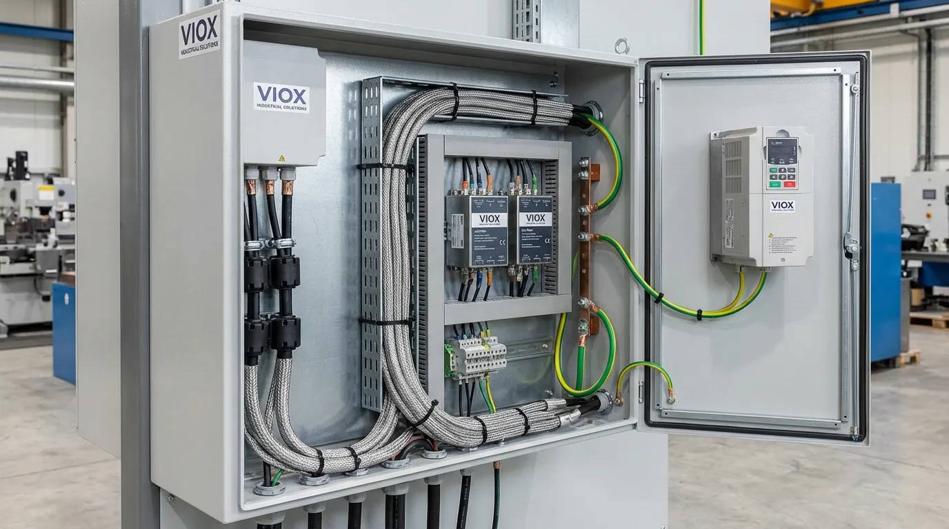
Účinné zmírnění EMI pro elektronické spouštěcí jednotky MCCB vyžaduje systematický přístup řešící rušení u zdroje, cesty vazby a přijímače. Správné instalační postupy tvoří základ zmírnění EMI. Udržování fyzické vzdálenosti mezi MCCB s elektronickými spouštěcími jednotkami a známými zdroji EMI (VFD, svařovací zařízení, RF vysílače) snižuje jak vyzařované, tak induktivní vazby. Doporučuje se minimální vzdálenost 30 cm od vysoce výkonných VFD a 50 cm od svařovacího zařízení, přičemž větší vzdálenosti poskytují další rezervu. Instalace MCCB do kovových skříní se správným uzemněním poskytuje stínění proti vyzařovanému EMI, přičemž skříň funguje jako Faradayova klec, která tlumí elektromagnetická pole.
Trasa kabelů a stínění významně ovlivňuje vazbu EMI. Napájecí a řídicí kabely by měly být vedeny mimo zdroje EMI, vyhýbat se paralelnímu vedení s výstupními kabely VFD, motorovými vodiči a dalšími vodiči s vysokou úrovní šumu. Pokud je paralelní vedení nevyhnutelné, udržování vzdálenosti alespoň 30 cm a použití kolmých křížení minimalizuje induktivní vazbu. Stíněné kabely pro komunikační a řídicí připojení poskytují ochranu proti vyzařovanému i kapacitnímu vazbě, přičemž stínění je uzemněno na jednom konci (pro nízkofrekvenční aplikace) nebo na obou koncích (pro vysokofrekvenční aplikace) v závislosti na konkrétní situaci. Použití kroucených párů vodičů pro signálové a řídicí vedení snižuje plochu smyčky a zlepšuje odolnost vůči vazbě magnetického pole.
Filtrování a potlačení komponenty zachycují rušení dříve, než dosáhne citlivých obvodů. Instalace síťových filtrů na napájecí zdroj elektronických spouštěcích jednotek tlumí rušení šířené vedením, přičemž výběr filtru je založen na frekvenčním spektru rušení. Feritová jádra nebo korálky na kabelech v blízkosti skříně spouštěcí jednotky potlačují vysokofrekvenční proudy v soufázovém režimu, aniž by ovlivnily požadované signály. Omezovače přechodného napětí (TVS) nebo varistory s oxidem kovu (MOV) na napájecích a řídicích vedeních omezují napěťové špičky a chrání před rázovými událostmi. RC obvody pro potlačení napěťových špiček na indukčních zátěžích (cívky relé, cívky stykačů) snižují amplitudu spínacích přechodných jevů u zdroje.
Uzemnění a pospojování postupy zajišťují, že stínění, skříně a rámy zařízení jsou správně připojeny, aby se vytvořila nízkoimpedanční cesta pro rušivé proudy. Jednobodové uzemnění skříně MCCB k hlavnímu uzemňovacímu systému zařízení zabraňuje zemním smyčkám a zároveň poskytuje účinné stínění. Pospojování všech kovových částí uvnitř skříně vytváří ekvipotenciální zónu, která minimalizuje rozdíly napětí, které by mohly pohánět rušivé proudy. Použití hvězdicové topologie uzemnění pro citlivé obvody odděluje zemní zpátečky s vysokým a nízkým proudem, čímž zabraňuje vazbě rušení prostřednictvím společné impedance uzemnění.
Výběr produktu aspekty zahrnují výběr MCCB s elektronickými spouštěcími jednotkami, které překračují minimální požadavky na odolnost podle normy IEC 60947-2 při provozu v obzvláště náročných elektromagnetických prostředích. Někteří výrobci nabízejí verze se zvýšenou odolností speciálně navržené pro aplikace s VFD nebo svařovací prostředí. Ověření, že spouštěcí jednotka byla testována podle příslušných norem odolnosti a kontrola zkušebních protokolů poskytuje jistotu v oblasti výkonu EMI. V extrémně náročných prostředích, kde je účinné zmírnění obtížné, mohou být termomagnetické spouštěcí jednotky spolehlivější volbou navzdory jejich snížené funkčnosti.
Metody testování a ověřování
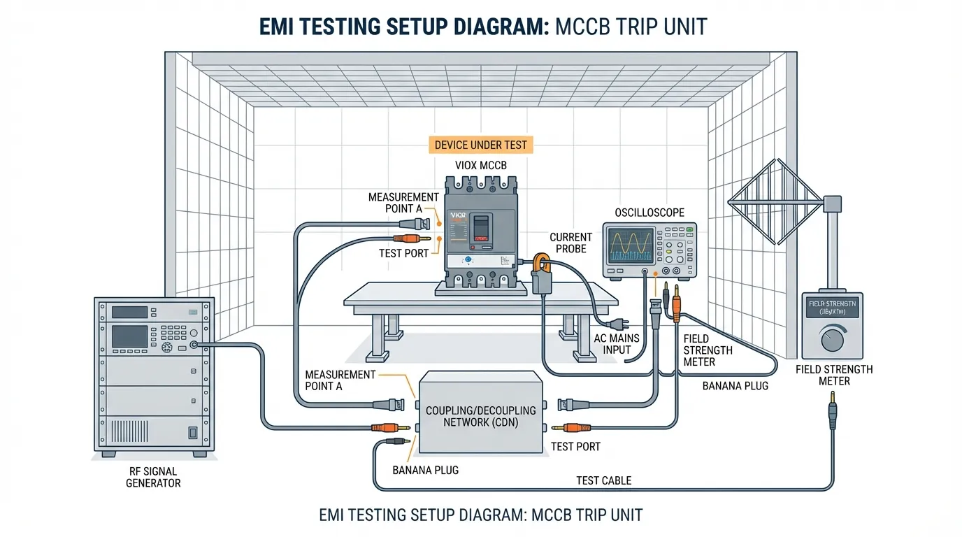
Validace odolnosti proti EMI a identifikace potenciálních problémů vyžaduje systematické testování na úrovni komponent i systému. Testování před instalací v kontrolovaném prostředí umožňuje ověření odolnosti spouštěcí jednotky před nasazením. Testování odolnosti proti vyzařování pomocí kalibrovaného generátoru RF signálu a antény vystavuje spouštěcí jednotku elektromagnetickým polím při různých frekvencích a amplitudách, přičemž se sleduje porucha nebo nežádoucí vypnutí. Testování odolnosti proti rušení šířenému vedením injektuje RF signály na napájecí a řídicí kabely pomocí vazebních/odvazebních sítí (CDN) nebo proudových injekčních sond. Testování odolnosti proti skupinám impulsů aplikuje rychlé přechodné jevy simulující spínací přechodné jevy k ověření správné funkce. Tyto testy by měly replikovat specifické prostředí EMI očekávané v instalaci, včetně frekvenčního obsahu, amplitudy a modulačních charakteristik.
Testování v terénu po instalaci validuje účinnost opatření pro zmírnění v reálném provozním prostředí. Měření intenzity elektromagnetického pole pomocí širokopásmového měřiče intenzity pole nebo spektrálního analyzátoru identifikuje amplitudu a frekvenční obsah okolního EMI v místě MCCB. Měření rušení šířeného vedením na napájecích a řídicích kabelech pomocí proudových sond a osciloskopů odhaluje rušení, které skutečně dosahuje spouštěcí jednotky. Funkční testování během provozu blízkých zdrojů EMI (spouštění VFD, provoz svařovacího zařízení, vysílání na rádiových systémech) ověřuje, že spouštěcí jednotka udržuje normální provoz bez nežádoucích vypnutí nebo chyb měření.
Monitorování a diagnostika poskytují průběžné ověřování odolnosti proti EMI a včasné varování před potenciálními problémy. Spouštěcí jednotky s funkcemi protokolování událostí by měly být nakonfigurovány tak, aby zaznamenávaly nežádoucí vypnutí, komunikační chyby a další anomálie, které mohou naznačovat problémy související s EMI. Pravidelná kontrola protokolovaných dat identifikuje vzorce, které korelují s provozem specifického zařízení nebo s časovými změnami elektromagnetického prostředí. Některé pokročilé spouštěcí jednotky zahrnují autodiagnostické funkce, které detekují a hlásí interní chyby potenciálně způsobené EMI, což umožňuje proaktivní zásah předtím, než dojde ke kritickému selhání.
Případová studie: Zmírnění EMI v aplikaci s VFD
Výrobní závod zaznamenal opakované nežádoucí vypínání MCCB chránících motory o výkonu 75 kW řízené frekvenčními měniči. Elektronické spouštěcí jednotky vypínaly náhodně během zrychlování a zpomalování motoru, což způsobovalo přerušení výroby v průměru třikrát za směnu. Počáteční vyšetřování odhalilo, že MCCB byly instalovány ve stejné skříni jako VFD, s nestíněnými řídicími kabely vedenými podél výstupních kabelů VFD. Měření elektromagnetického pole ukázala intenzitu vyzařovaného pole přesahující 30 V/m v místech MCCB během spínání VFD, což je třikrát více než testovací úroveň podle normy IEC 60947-2.
Implementovaná strategie pro zmírnění zahrnovala přemístění MCCB do samostatné kovové skříně umístěné 1 metr od skříně VFD, instalaci síťových filtrů dimenzovaných pro aplikace s VFD na napájecí zdroj každé elektronické spouštěcí jednotky, nahrazení nestíněných řídicích kabelů stíněnými kroucenými páry kabelů se stíněním uzemněným na obou koncích, instalaci feritových jader na všechny kabely vstupující do skříně MCCB a vedení napájecích kabelů v samostatných chráničkách od výstupních kabelů VFD s minimální vzdáleností 50 cm. Po implementaci těchto opatření se intenzita pole v místech MCCB snížila pod 8 V/m a rušení šířené vedením na napájecích kabelech se snížilo o 25 dB.
Závod fungoval šest měsíců po úpravách bez jediného nežádoucího vypnutí, čímž se eliminovaly odhadované náklady na prostoje ve výši 45 000 USD ročně. Tento případ ukazuje, že systematické zmírnění EMI řešící více cest vazby může vyřešit i závažné problémy s rušením a že náklady na správné zmírnění jsou obvykle mnohem nižší než náklady na opakovaná přerušení výroby.
Výběr správného MCCB pro vaši aplikaci
Volba mezi elektronickými a termomagnetickými spouštěcími jednotkami vyžaduje pečlivé vyhodnocení požadavků aplikace, elektromagnetického prostředí a provozních priorit. Elektronické spouštěcí jednotky jsou optimální volbou pro aplikace vyžadující přesnou koordinaci ochrany, programovatelná nastavení, zemní ochranu s nastavitelnou citlivostí, komunikační integraci se systémy správy budov nebo SCADA, protokolování dat a monitorování kvality napájení nebo zónové selektivní blokování. Tyto výhody je však třeba zvážit oproti zvýšené náchylnosti k EMI a požadavkům na zmírnění.
Termomagnetické spouštěcí jednotky zůstávají preferovanou volbou pro aplikace v náročných elektromagnetických prostředích, kde je účinné zmírnění obtížné, instalace v blízkosti vysoce výkonných VFD nebo svařovacího zařízení bez fyzického oddělení, venkovní instalace nebo instalace v náročných prostředích, kde může být narušena integrita skříně, aplikace, kde je maximální spolehlivost upřednostňována před pokročilými funkcemi, nebo situace modernizace, kde je přidání opatření pro zmírnění EMI nepraktické. Inherentní odolnost termomagnetických mechanismů vůči elektromagnetickému rušení poskytuje robustní ochranu bez nutnosti speciálních instalačních postupů nebo dalších komponent pro zmírnění.
Pro aplikace, kde jsou elektronické spouštěcí jednotky vybrány navzdory náročným prostředím EMI, poskytuje specifikace jednotek se zvýšenou odolností nad minimální požadavky normy IEC 60947-2 další rezervu. Někteří výrobci nabízejí elektronické spouštěcí jednotky průmyslové kvality nebo dimenzované pro VFD s úrovněmi odolnosti 20-30 V/m nebo vyššími, speciálně navržené pro náročná elektromagnetická prostředí. Kontrola testovacích dat a certifikací výrobce zajišťuje, že vybraná spouštěcí jednotka byla validována pro specifické prostředí EMI očekávané v instalaci.
Související zdroje
Pro komplexní pochopení výběru MCCB, koordinace ochrany a návrhu elektrického systému prozkoumejte tyto související příručky VIOX:
- Co je to lisovaný jistič (MCCB)? – Kompletní průvodce konstrukcí, provozem a aplikacemi MCCB
- Pochopení jízdních křivek – Základní průvodce koordinací ochrany a výběrem křivek
- Jak vybrat MCCB pro panel – Komplexní metodika výběru MCCB
- MCCB vs MCB – Podrobné srovnání typů jističů
- Průvodce nastavitelnými jističi – Pochopení nastavitelných spouštěcích nastavení
- Hodnoty jističů ICU ICS ICW ICM – Vypínací schopnost a specifikace jmenovitých hodnot
- Průvodce komponentami průmyslového řídicího panelu – Kompletní návrh panelu a výběr komponent
- Elektrické snížení jmenovitého proudu Teplota Nadmořská výška Skupinové faktory – Snížení jmenovitého proudu vlivem prostředí pro přesnou ochranu
- Diagnostická příručka pro bzučení jističe – Odstraňování problémů s abnormálním provozem jističe
- Typy jističů – Komplexní přehled technologií jističů
Často Kladené Otázky
Otázka: Může EMI trvale poškodit elektronické spouštěcí jednotky MCCB?
Odpověď: Zatímco většina událostí EMI způsobuje dočasné poruchy, jako je nežádoucí vypínání nebo falešné odečty, závažné elektromagnetické poruchy mohou potenciálně způsobit trvalé poškození citlivých elektronických komponent. Vysokoenergetické přechodné jevy z úderů blesku nebo spínacích rázů mohou překročit jmenovité napětí polovodičových zařízení, což způsobí okamžité selhání. Opakované vystavení vysoké úrovni EMI může také způsobit kumulativní degradaci komponent, což snižuje dlouhodobou spolehlivost. Správná ochrana proti rázům a opatření pro zmírnění EMI zabraňují dočasným poruchám i trvalému poškození.
Otázka: Jak poznám, zda je mé nežádoucí vypínání způsobeno EMI?
Odpověď: Nežádoucí vypnutí související s EMI obvykle vykazují charakteristické vzorce, které je odlišují od vypnutí způsobených skutečným přetížením nebo poruchami. Mezi klíčové indikátory patří vypnutí, ke kterým dochází během provozu specifického zařízení (spouštění VFD, svařovací operace, rádiové přenosy), vypnutí bez odpovídajícího důkazu o nadproudu (žádné tepelné poškození, jiná ochranná zařízení nefungovala), vypnutí, ke kterým dochází náhodně bez korelace se změnami zátěže, a vypnutí, která přestanou po implementaci opatření pro zmírnění EMI. Měření elektromagnetického pole a testování rušení šířeného vedením mohou definitivně identifikovat EMI jako hlavní příčinu.
Otázka: Existují průmyslové normy pro odolnost proti EMI nad rámec normy IEC 60947-2?
Odpověď: Ano, v závislosti na aplikaci a geografické poloze se může vztahovat několik dalších norem. MIL-STD-461 specifikuje přísnější požadavky na EMI pro vojenské a letecké aplikace. EN 50121 se zabývá železničními aplikacemi se specifickými požadavky na odolnost pro kolejová vozidla a traťové zařízení. IEC 61000-6-2 poskytuje generické normy odolnosti pro průmyslová prostředí, na které lze odkazovat kromě norem specifických pro produkt. UL 508A zahrnuje požadavky na EMC pro průmyslové řídicí panely v Severní Americe. Soulad s více normami poskytuje větší jistotu spolehlivého provozu v různých elektromagnetických prostředích.
Otázka: Mohu dodatečně vybavit ochranu proti EMI stávající MCCB s elektronickými spouštěcími jednotkami?
Odpověď: Ano, mnoho opatření pro zmírnění EMI lze implementovat jako dodatečné úpravy stávajících instalací. Přidání síťových filtrů k napájecím připojením, instalace feritových jader na kabely, implementace správného vedení a oddělení kabelů, zlepšení uzemnění a pospojování a přidání stínění ke skříním lze provést bez výměny samotných MCCB. Pokud však spouštěcí jednotky postrádají odpovídající inherentní odolnost, mohou tato externí opatření poskytnout pouze částečné zlepšení. V náročných prostředích EMI může být výměna elektronických spouštěcích jednotek za termomagnetické typy nejefektivnějším řešením.
Otázka: Jaký je typický rozdíl v ceně mezi elektronickými a termomagnetickými MCCB?
Odpověď: Elektronické spouštěcí jednotky obvykle stojí o 50-150 % více než ekvivalentní termomagnetické MCCB, přičemž prémie se zvyšuje u jednotek s pokročilými funkcemi, jako je komunikace, zemní ochrana a zvýšená odolnost. U MCCB 400A může základní termomagnetická jednotka stát 300-500 USD, zatímco elektronická verze se pohybuje od 600-1200 USD. Toto srovnání by však mělo zahrnovat náklady na opatření pro zmírnění EMI (filtry, stíněné kabely, samostatné skříně), které mohou přidat 100-500 USD na instalaci. Celkový rozdíl v nákladech na instalaci může být 75-200 %, což činí termomagnetické jednotky výrazně ekonomičtějšími pro aplikace, které nevyžadují funkce elektronických spouštěcích jednotek.
Otázka: Jak často by se měla testovat odolnost proti EMI v provozních zařízeních?
Odpověď: Počáteční testování by mělo být provedeno během uvádění do provozu, aby se ověřila správná funkce ve skutečném elektromagnetickém prostředí. Periodické opakované testování se doporučuje po jakýchkoli významných změnách v zařízení, včetně instalace nového vysoce výkonného zařízení (VFD, svařovací systémy, RF zařízení), úprav elektrických rozvodných systémů nebo přemístění MCCB nebo zdrojů EMI. Roční testování je rozumné pro kritické aplikace, kde má nežádoucí vypínání závažné důsledky. Průběžné monitorování prostřednictvím protokolování událostí a diagnostických funkcí poskytuje průběžné ověřování bez nutnosti formálního testování.
Závěr
Elektromagnetické rušení představuje významnou výzvu pro elektronické spouštěcí jednotky MCCB v průmyslových prostředích, ale systematické porozumění a zmírnění mechanismů vazby EMI umožňuje spolehlivý provoz i v elektromagneticky náročných podmínkách. Vynikající přesnost, flexibilita a komunikační schopnosti elektronických spouštěcích jednotek je činí stále atraktivnějšími pro moderní elektrické systémy, za předpokladu, že je věnována náležitá pozornost odolnosti proti EMI během výběru produktu, návrhu instalace a ověřování při uvádění do provozu.
Zásadní kompromis mezi pokročilou funkčností a inherentní odolností vůči EMI vyžaduje pečlivé vyhodnocení požadavků aplikace a elektromagnetického prostředí. Pro aplikace, kde jsou nezbytné funkce elektronické spouštěcí jednotky, implementace komplexních opatření pro zmírnění EMI – včetně správných instalačních postupů, vedení a stínění kabelů, filtrování a potlačovacích komponent a efektivního uzemnění – zajišťuje spolehlivou ochranu bez rušivých vypnutí. Pro aplikace v náročných prostředích s EMI, kde je zmírnění obtížné nebo nepraktické, poskytují tepelně-magnetické spouštěcí jednotky robustní ochranu s inherentní imunitou vůči elektromagnetickému rušení.
Jak se elektrické systémy neustále vyvíjejí s rostoucí digitalizací, komunikační integrací a obsahem výkonové elektroniky, elektromagnetické prostředí bude postupně náročnější. Výrobci reagují vylepšenými návrhy imunity, vylepšeným stíněním a robustnějšími algoritmy firmwaru. Odpovědnost za úspěšnou aplikaci však nakonec spočívá na projektantech a instalatérech systémů, kteří musí rozumět mechanismům vazby EMI, implementovat účinné strategie zmírnění a ověřit správnou funkci prostřednictvím systematického testování. Dodržováním zásad a postupů uvedených v této příručce mohou elektroprofesionálové s jistotou nasazovat elektronické spouštěcí jednotky MCCB, které poskytují pokročilé možnosti ochrany se spolehlivostí požadovanou kritickými průmyslovými aplikacemi.
O společnosti VIOX Electric: VIOX Electric je přední B2B výrobce elektrických zařízení, specializující se na vysoce kvalitní MCCB, jističe a elektrická ochranná zařízení pro průmyslové, komerční a infrastrukturní aplikace. Naše produkty splňují mezinárodní normy včetně IEC 60947-2, UL 489 a GB 14048, s komplexním testováním EMC zajišťujícím spolehlivý provoz v náročných elektromagnetických prostředích. Pro technickou podporu, pomoc s výběrem produktu nebo řešení na míru kontaktujte náš inženýrský tým.
