
Proč integrace solárního systému a generátoru narušuje standardní systémy ATS
Prudký nárůst hybridních solárních instalací – kombinujících fotovoltaické panely, bateriové úložiště a záložní generátory – odhalil kritickou slabinu v konvenční technologii automatických přepínačů. Majitelé nemovitostí, kteří investují 20 000–50 000 USD do solárních systémů, příliš pozdě zjistí, že jejich stávající generátorový ATS nemůže koordinovat se solárními střídači, což vytváří nebezpečné konflikty uzemnění neutrálu, rušivé výpadky zemního spojení a úplné selhání systému během nouzových situací.
Hlavní příčina spočívá v zásadních neslučitelnostech mezi standardními jednotkami ATS kompatibilními s generátory navrženými pro tradiční záložní generátory a systémy solárních střídačů spravujícími napětí baterie, kolísající výrobu FV a složité priority zdrojů energie. Standardní generátorová zařízení ATS očekávají proprietární řídicí signály 12 V DC, pevné spoje neutrálu a uzemnění a předvídatelné výstupy napětí/frekvence – nic z toho solární střídače spolehlivě neposkytují.
Tato technická příručka řeší rozhodnutí mezi ATS připraveným pro FV a standardním generátorovým ATS vysvětlením technických neslučitelností, poskytnutím kritérií výběru na základě architektury systému, podrobným popisem správné koordinace uzemnění neutrálu a zajištěním shody s NEC pro bezpečné řízení tří zdrojů energie v moderních hybridních instalacích.
Část 1: Pochopení provozu ATS v hybridních systémech solárního systému + generátoru
1.1 Čím se solární ATS liší od generátorového ATS
Standardní generátorové ATS zařízení sledují přímočarou sekvenci: když selže napájení ze sítě, ATS detekuje ztrátu napětí, vyšle reléový signál 12 V DC pro spuštění generátoru, monitoruje výstup, dokud se napětí a frekvence nestabilizují (10–15 sekund), a poté přepne zátěže. To předpokládá, že záložní zdroj může komunikovat stav připravenosti a oba zdroje udržují konzistentní napětí/frekvenci s předvídatelným uzemněním neutrálu.
Požadavky solárního střídače na ATS se zásadně liší. Solární střídače nemohou vysílat proprietární signály 12 V DC, jejich napětí kolísá se stavem nabití baterie a výrobou solární energie a jejich uzemnění neutrálu se liší podle výrobce. ATS kompatibilní se solárním systémem musí monitorovat napětí baterie spíše než stav generátoru, koordinovat milisekundové přepínání, aby se zabránilo narušení elektroniky, a přizpůsobit se konstrukcím s plovoucím neutrálem, které by způsobily výpadky zemního spojení u standardních jednotek. Pochopení základů automatického přepínače vyžaduje rozpoznání těchto architektonických rozdílů.
Klíčová neslučitelnost se objevuje v řídicí signalizaci. Většina záložních generátorů pro domácnosti komunikuje pomocí proprietárních protokolů navržených pro konkrétní rodiny generátorů. Solární střídače, zejména hybridními invertorovými systémy, generují střídavý proud, kdykoli baterie obsahují dostatečné nabití, bez “signálu připravenosti” indikujícího stabilní provoz.
1.2 Výzva tří zdrojů energie
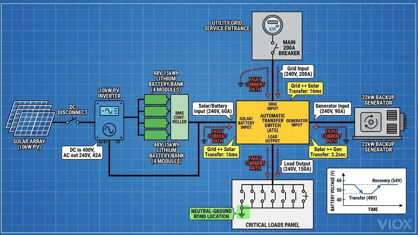
Moderní hybridní solární instalace spravují tři odlišné zdroje energie s různými charakteristikami:
- Elektrická síť slouží jako primární v systémech připojených k síti, poskytuje neomezenou kapacitu, předvídatelné napětí/frekvenci a inherentní uzemnění neutrálu na vstupu do budovy.
- Solární střídač + baterie funguje jako primární v ostrovních instalacích nebo preferovaný zdroj v systémech s prioritou solární energie. Poskytuje omezenou kapacitu na základě SOC baterie a výroby solární energie v reálném čase. Kritický rozdíl: solární systém s bateriovým zálohováním pracuje tiše, produkuje nulové emise a nestojí nic za kWh.
- Záložní generátor poskytuje nouzové napájení, když selžou zdroje ze sítě i solární/bateriové zdroje nebo SOC baterie klesne pod bezpečná minima. Generátory poskytují vysokou kapacitu s předvídatelným napětím/frekvencí, ale spotřebovávají palivo, vyžadují údržbu a produkují hluk/emise.
| Provozní scénář | Primární zdroj | Sekundární zdroj | Stav zátěže | Požadovaná akce ATS |
|---|---|---|---|---|
| Normální provoz | Síť (nebo solární v ostrovním režimu) | Baterie nabitá, solární systém vyrábí | Všechny zátěže napájeny | ATS na primárním zdroji, žádná akce |
| Výpadek sítě, baterie nabitá | Solární/baterie | Generátor v pohotovosti | Pouze kritické zátěže (pokud je implementováno odlehčení zátěže) | ATS přepne na solární/baterii (milisekundy) |
| Výpadek sítě, baterie vybitá | Generátor | Solární systém dobíjí baterii | Pouze základní zátěže | ATS přepne na generátor (sekundy), začne dobíjení baterie |
| Přechod všech zdrojů | Proměnlivé (probíhá předávání) | K dispozici/nedostupné více zdrojů | Možné krátkodobé přerušení | ATS koordinuje vícestupňové přepínání s prioritní logikou |
Pochopení této hierarchie se ukazuje jako zásadní při výběru typů přepínačů protože různé architektury ATS řeší priority zdrojů s velmi odlišnou úrovní sofistikovanosti.
1.3 Uzemnění neutrálu: Skrytý zabiják kompatibility
Na stránkách spojení neutrálu a uzemnění (N-G) představuje záměrné elektrické spojení mezi neutrálním vodičem a uzemňovacím systémem na jednom konkrétním místě. Toto spojení poskytuje cestu s nízkou impedancí pro poruchový proud zpět ke zdroji, což umožňuje rychlé vypnutí nadproudové ochrany. Článek 250.30 NEC nařizuje přesně JEDEN spoj neutrálu a uzemnění na každý samostatně odvozený systém.
Uzemnění generátoru ve standardních jednotkách obvykle zahrnuje vnitřní propojení N-G – výrobce generátoru propojuje neutrál se zemí uvnitř krytu. To funguje perfektně v tradičních instalacích ATS s generátorem, kde ATS přerušuje oba fázové vodiče A NEUTRÁL během přepínání, čímž se dodržuje pravidlo “jednoho propojení”.
Uzemnění solárního střídače konfigurace se u jednotlivých výrobců a topologií instalace výrazně liší. Některé mají plovoucí nulový vodič konstrukce bez vnitřního propojení, které počítají s externím uzemněním v rozvaděči. Jiné zahrnují vnitřní propojení (zejména modely mimo síť). Hybridní střídače mohou nabízet konfigurovatelné propojení pomocí nastavení propojek.
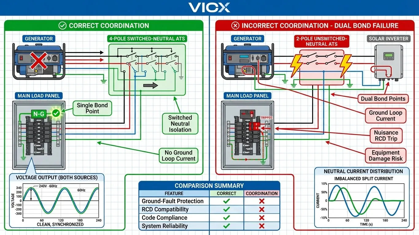
Katastrofický scénář nastane, když dodavatelé připojí standardní generátorový ATS k solárnímu systému, kde má střídač také vnitřní propojení – čímž vznikne duální propojení nulového vodiče se zemí. Se dvěma uzemňovacími body se nulový proud dělí mezi nulový vodič a zemnící vodič, což způsobuje:
- Nežádoucí vypínání proudových chráničů/GFCI: Zařízení detekují nevyvážený proud a interpretují to jako zemní poruchu
- Rušení zemní smyčkou: Proud protékající zemnícími vodiči vytváří elektromagnetické rušení
- Zvýšený zemní potenciál: Úbytek napětí na impedanci zemnícího vodiče může vytvářet nebezpečí úrazu elektrickým proudem
- Selhání koordinace jističů: Zemní proud nemusí dosáhnout dostatečné velikosti k vypnutí nadřazených zařízení
Možnosti řešení vyžadují mapování konfigurace propojení před výběrem ATS:
- Použijte generátor připravený pro FV s žádným vnitřním propojením N-G, nainstalujte jediné propojení N-G v rozvaděči nebo umístění ATS
- Použijte ATS s přepínaným neutrálem , který zcela izoluje každý zdroj včetně nulového vodiče
- Nainstalujte izolační relé , které mechanicky odpojí propojení N-G generátoru, když je aktivní solární/bateriový systém
Porozumění správné zásady uzemnění a propojení nulového vodiče se zemí zabraňuje nejčastější příčině selhání integrace solárního generátoru.
Část 2: Generátory připravené pro FV vs. standardní generátory
2.1 Co je to generátor “připravený pro FV”?
Generátory připravené pro FV zahrnují hardwarové a řídicí funkce, které řeší konflikty propojení neutrálu, nekompatibilitu snímání napětí a neshody řídicích signálů, které trápí konvenční integraci generátoru a solárního systému.
Mezi hlavní funkce patří:
- Volitelné nebo žádné propojení N-G: Vnitřní propojka nebo odnímatelný propojovací pásek umožňuje konfiguraci instalátorem na základě architektury systému, čímž se zabrání katastrofám s duálním propojením
- Kompatibilní výstupní napětí/frekvence: Přísnější regulace napětí (±3 % oproti ±5 %) a přesné řízení frekvence (59,8–60,2 Hz) odpovídají výstupním charakteristikám solárního střídače
- Chytrý ovladač bez proprietární komunikace ATS: Přijímá standardní sepnutí relé nebo signály přítomnosti napětí spíše než protokoly specifické pro výrobce
- Flexibilita startovacího signálu: Více možností spouštěcího signálu včetně sepnutí relé bez napětí, snímání přítomnosti/absence napětí a programovatelného zpožděného startu
Generátory připravené pro FV stojí o 15–30 % více než standardní modely, ale představují pouze 3–5 % celkových nákladů systému v instalacích za 30 000–50 000 USD – malá investice, která zabrání značným nákladům na odstraňování problémů.
2.2 Standardní generátory: Proč vytvářejí problémy
Standardní záložní generátory pro domácnosti a komerční provozy fungují bezchybně v tradičních aplikacích generátorů, ale vytvářejí několik překážek při kombinaci s moderními hybridními invertorovými systémy.
Pevné propojení N-G trvale propojuje neutrál s uzemněním rámu generátoru bez možnosti rekonfigurace. Dokonce i generátory s přístupnými propojkami často vyžadují značnou demontáž a zrušení záruky, pokud jsou odstraněny.
Proprietární komunikace přepínacího spínače protokoly používají signály specifické pro výrobce – Generac používá dvouvodičové 12 V DC, Kohler implementuje různé úrovně napětí. Tyto protokoly nelze replikovat solárními střídači, což způsobuje, že standardní jednotky ATS odmítají přepínat zátěže na solární/bateriové zdroje.
Charakteristiky výstupního napětí standardních generátorů upřednostňují splnění požadavků norem (regulace napětí ±5 %, tolerance frekvence ±3 %) při minimalizaci nákladů. Během přechodných jevů zátěže může pokles napětí nebo pokles frekvence překročit úzká okna požadovaná solárními střídači s ochranou proti ostrovnímu provozu podle IEEE 1547, což způsobí odpojení střídačů z bezpečnostních důvodů.
Žádné monitorování napětí baterie znamená, že standardní řídicí jednotky generátoru nemají žádné povědomí o stavu solárního systému a běží nepřetržitě během výpadků proudu, i když je solární výroba a kapacita baterie dostatečná.
2.3 Srovnávací tabulka: Generátor připravený pro FV vs. standardní generátor
| Funkce | Generátor připravený pro FV | Standardní generátor |
|---|---|---|
| Propojení nulového vodiče se zemí | Konfigurovatelné pomocí propojky/přepínače; často žádné vnitřní propojení, počítá s externím propojením v rozvaděči | Pevné vnitřní propojení; odstranění propojení obvykle ruší záruku nebo vyžaduje servis v továrně |
| Startovací řídicí signál | Přijímá sepnutí relé, spoušť snímání napětí nebo programovatelné zpoždění; není vyžadován žádný proprietární protokol | Proprietární komunikace 12 V DC s ATS odpovídající značky; nekompatibilní s generickými ATS se snímáním napětí |
| Stabilita výstupního napětí | Regulace ±2–3 %, přísné řízení frekvence (59,9–60,1 Hz) pro přizpůsobení oknům proti ostrovnímu provozu střídače | Regulace ±5 %, tolerance frekvence ±3 %; může překročit prahové hodnoty odpojení střídače během přechodných jevů |
| Kompatibilita ATS | Pracuje s ATS snímajícími napětí, řízenými napětím baterie a inteligentními programovatelnými ATS od libovolného výrobce | Vyžaduje ATS od stejného výrobce s proprietární komunikací; výrazně omezuje výběr ATS |
| Integrace solárního systému | Navrženo pro koordinaci se solárními střídači; výrobci poskytují schémata zapojení/kabeláže pro hybridní systémy | Vyžaduje řešení, vlastní reléovou logiku nebo přepracování systému; žádná podpora výrobce pro integraci solárního systému |
| Typická cenová prémie | O 15-30 % vyšší než u standardních modelů; dalších 1 500-3 000 Kč pro rezidenční jednotky o výkonu 10-22 kW | Základní cena; 5 000-12 000 Kč pro rezidenční záložní generátor o výkonu 10-22 kW |
| Sledování napětí baterie | Některé modely obsahují vstupy pro monitorování napětí baterie; mohou oddálit start, dokud se baterie nevybije | Žádné monitorování baterie; spouští se okamžitě, když ATS signalizuje, bez ohledu na dostupnost baterie/solární energie |
| Nejlepší případ použití | Hybridní solární + bateriové + generátorové systémy, kde jsou solární/bateriové systémy primárními záložními zdroji | Tradiční zálohování ze sítě generátorem bez solární energie; aplikace, kde je generátor jediným záložním zdrojem |
Část 3: Výběr správného ATS pro váš solární systém
3.1 Kritéria pro výběr
Jmenovité napětí a proud musí zvládnout trvalý proud a napětí přítomné během normálního provozu plus nárazové proudy během spouštění motoru. Srovnejte jmenovitý trvalý proud ATS s trvalým výstupem střídače (ne s nárazovým proudem). 10kW střídač produkující 240V dělený fázový výstup dodává přibližně 42A trvale, což naznačuje 60A nebo 80A ATS pro snížení jmenovitého výkonu.
Čas přestupu určuje, jak rychle ATS přepíná mezi zdroji. Standardní jednotky zaměřené na generátory přepínají za 10-30 sekund, což je přijatelné pro běžné spotřebiče, ale nevhodné pro počítače nebo lékařské vybavení. Solárně kompatibilní jednotky ATS pracující mezi sítí a baterií/střídačem dosahují doby přepnutí 10-20 milisekund – dostatečně rychle na udržení provozu počítače a zabránění resetování PLC.
Metoda kontroly definuje, jak ATS detekuje dostupnost zdroje:
- ATS snímající napětí monitoruje přítomnost střídavého napětí na každém vstupním zdroji, nevyžaduje žádnou komunikaci mezi ATS a zdroji – nejvíce kompatibilní se solární energií
- ATS řízené signálem vyžaduje, aby záložní zdroj odeslal aktivní řídicí signál potvrzující připravenost – nekompatibilní se solárními střídači
- ATS monitorující napětí baterie nepřetržitě měří stejnosměrné napětí baterie a zahajuje přepnutí na základě prahových hodnot napětí – optimální pro architektury s prioritou solární energie
Konfigurace uzemnění: Nepřepínaný nulový vodič Jednotky ATS přepínají fázové vodiče při zachování nepřetržitého nulového připojení, což vyžaduje, aby všechny zdroje sdílely společný bod uzemnění. Přepínaný nulový vodič Jednotky ATS mechanicky odpojují jak fázové vodiče, TAKŽE i nulový vodič, čímž zcela izolují každý zdroj a umožňují nezávislé uzemnění.
3.2 Běžné typy ATS pro solární aplikace
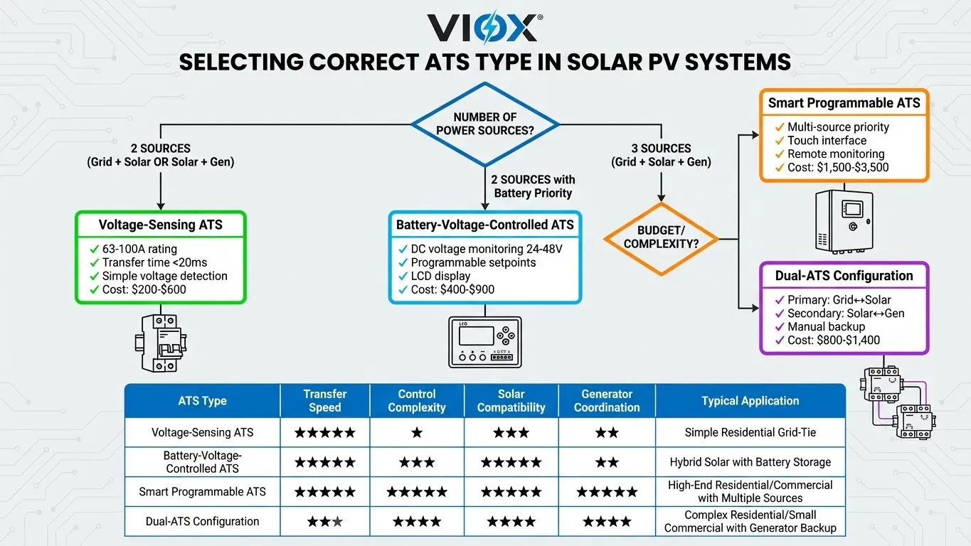
Ruční přepínač (MTS) představuje nejlevnější a nejspolehlivější řešení – ručně ovládaný přepínač, který fyzicky přepíná zátěže mezi zdroji. Eliminuje složitost řízení a problémy s kompatibilitou komunikace, ale vyžaduje přítomnost obsluhy a zátěže během přepínání zažívají úplné přerušení.
Automatický ATS snímající napětí monitoruje přítomnost střídavého napětí a automaticky přepíná, když primární zdroj klesne pod prahovou hodnotu. Funguje ideálně pro systémy s prioritou solární energie, protože solární střídače přirozeně poskytují napětí, kdykoli baterie udržují nabití, což nevyžaduje žádnou speciální signalizaci.
ATS řízené napětím baterie nepřetržitě monitoruje stejnosměrné napětí baterie a přepíná ze solární/baterie na síť/generátor, když napětí klesne pod naprogramované minimum. Optimalizuje využití solární energie – zátěže zůstávají na baterii/střídači, dokud baterie udržují dostatečné nabití. Nastavené body přepnutí se obvykle pohybují od 42-48 V pro 48V lithiové systémy.
Chytrý/programovatelný ATS obsahuje mikroprocesorové řízení s uživatelsky konfigurovatelnými parametry pro prahové hodnoty napětí, zpoždění přepnutí, priority zdrojů a provozní režimy. Pokročilé modely komunikují prostřednictvím Modbus nebo Ethernet pro vzdálené monitorování. Nejvhodnější pro složité hybridní systémy, kde strategie řízení energie přinášejí měřitelnou hodnotu.
3.3 Kontrolní seznam pro dimenzování a specifikaci
- Vypočítejte maximální trvalé zatížení sečtením jmenovitého proudu zálohovaných obvodů a přidáním 20-25% rezervy
- Ověřte, zda výstupní napětí střídače odpovídá jmenovitému napětí ATS (120 V, 240 V, 120/240 V dělená fáze)
- Určete požadovaný počet pólů: 2P pouze pro fázové vodiče, 4P pro dělenou fázi s přepínaným nulovým vodičem
- Identifikujte konfiguraci uzemnění všech zdrojů prostřednictvím dokumentace výrobce nebo testování kontinuity
- Potvrďte kompatibilitu signálu spouštění generátoru – proprietární nebo generické sepnutí relé
- Zkontrolujte seznam UL 1008 nebo ekvivalentní certifikaci
- Ověřte programovatelnost pro nastavené body napětí baterie, pokud používáte ATS řízené napětím
- Posuďte požadavky na dobu přepnutí na základě citlivosti zátěže
3.4 Osvědčené postupy instalace
Umístění: Namontujte ATS v blízkosti hlavního servisního panelu, abyste minimalizovali délky obvodů a pokles napětí. Zajistěte dostatečný prostor podle NEC 110.26 (obvykle 36 palců vpředu, 30 palců na šířku, 6,5 stopy na výšku). Zvažte montáž v blízkosti bateriového bloku pro typy řízené napětím baterie, abyste minimalizovali délku snímacího vodiče DC.
Zapojení: Nainstalujte samostatné kabelové trasy pro přívody ze sítě, solární energie a generátoru. Použijte správně dimenzované vodiče na základě jmenovitého proudu ATS a délky obvodu. Barevně označte vodiče zdroje: síť (černá/červená/bílá/zelená), solární (modrá/žlutá/bílá/zelená), generátor (hnědá/oranžová/bílá/zelená).
Pospojování: Nainstalujte uzemnění neutrálu na přesně jednom místě – buď na svorkách ATS, na prvním rozvodném panelu za ATS, nebo na střídači/generátoru (pouze s ATS s přepínaným neutrálem). Otestujte konfiguraci uzemnění po instalaci ověřením kontinuity mezi neutrálem a zemí s jedním zdrojem pod napětím.
Uzemnění: Všechny zdroje musí odkazovat na stejný systém zemnící elektrody. Připojte zem šasi solárního střídače, zem rámu generátoru a zemnící svorku ATS k systému zemnící elektrody budovy pomocí správně dimenzovaných zemnících vodičů podle NEC tabulky 250.66. Odkaz požadavky na systém zemnící elektrody pro správné dimenzování.
Označování: Nainstalujte trvalé štítky na ATS s uvedením názvů a napětí zdrojů, jmenovitého výkonu přepínače a konfigurace uzemnění. Podle NEC 705, řádně označte všechny komponenty solárního systému identifikující zdroje energie a odpojovací prostředky.
Část 4: Integrační strategie a návrh systému
4.1 Architektura "Solar-First"
Architektura "Solar-first" upřednostňuje solární střídač + baterii jako primární zálohu při výpadku sítě, generátor se spouští až po poklesu SOC baterie pod definované prahové hodnoty. Tím se maximalizuje využití obnovitelné energie a minimalizuje spotřeba paliva.
Implementace vyžaduje ATS řízený napětím baterie s programovatelnými nastavenými body. Nakonfigurujte přenosové napětí na minimální doporučené hodnotě výrobce baterie při zatížení – lithiové LiFePO4 baterie obvykle specifikují minimum 2,8 V na článek (44,8 V pro 48V systémy), ale přenos by měl probíhat o 2-4 V výše. Nastavte obnovovací napětí o 4-6 V nad přenosové napětí, abyste zajistili dostatečné dobití před obnovením provozu baterie.
Typické nastavené body:
- Konzervativní: Přenos při 50 V (50% SOC), obnova při 54 V (80% SOC) – maximální životnost baterie
- Vyvážené: Přenos při 48 V (30% SOC), obnova při 53 V (70% SOC) – optimalizované využití
- Agresivní: Přenos při 46 V (20% SOC), obnova při 52 V (60% SOC) – maximální využití solární energie
Řízení zátěže vylepšuje architekturu "solar-first" implementací automatického odpojování zátěže při provozu na baterii. Chytré jističe odpojí nepodstatné zátěže a rezervuje kapacitu baterie pro kritické zátěže.
4.2 Solární systém připojený k síti se zálohou generátoru
Solární systém připojený k síti se zálohou generátoru představuje nejjednodušší hybridní architekturu. Solární střídač je trvale připojen prostřednictvím standardního síťového propojení, zatímco samostatný ATS zajišťuje přepínání mezi sítí a generátorem. Střídač exportuje přebytečnou solární produkci do sítě a pracuje nezávisle na záložním napájení.
To zjednodušuje výběr přepínače tím, že eliminuje požadavky na koordinaci solárního systému – ATS provádí tradiční přepínání mezi dvěma zdroji (síť ↔ generátor). Při výpadku sítě ATS signalizuje spuštění generátoru a přepne zátěže. Solární střídač může pokračovat v provozu, pokud generátor poskytuje napětí a frekvenci v rozsahu sledování sítě (typicky ±5% napětí, ±0,5 Hz frekvence podle IEEE 1547).
Kritickou výzvou je kvalita regulace napětí generátoru. Standardní generátory s regulací ±5% mohou způsobit odpojení střídačů připojených k síti během provozu generátoru. Řešení zahrnují specifikaci generátoru "PV-ready" s přísnější regulací nebo akceptování vypnutí solárního systému během provozu generátoru.
4.3 Koordinace tří zdrojů
Hybridní systémy se třemi zdroji koordinují síť, solární střídač + baterii A záložní generátor s programovatelnou prioritou zdrojů a inteligentním řízením zátěže. To poskytuje maximální energetickou nezávislost a spolehlivost, ale vyžaduje podstatně více inženýrského úsilí a investic do vybavení.
Implementace vyžaduje konfiguraci se dvěma ATS nebo specializovaný inteligentní přepínač se třemi zdroji. V provedení se dvěma ATS zajišťuje primární přepínač přepínání v milisekundách mezi sítí a solárním systémem/baterií, zatímco sekundární přepínač řídí pomalejší přechody mezi solárním systémem/baterií a generátorem.
Typická prioritní logika:
- Primární: Solární systém/Baterie (když je baterie nabitá nad 60% SOC) – maximalizace vlastní spotřeby
- Sekundární: Síť (když solární systém/baterie není k dispozici nebo je baterie pod 40% SOC) – spolehlivá záloha
- Terciární: Generátor (když síť selže A baterie je vybitá pod 30% SOC) – pouze nouzové řešení
Koordinace tří zdrojů přidává 5 000–15 000 USD v řídicích systémech, dalších přepínačích a inženýrských pracích. Tato investice má smysl pro komerční provozy s vysokými náklady na elektřinu, off-grid nemovitosti s omezenými solárními zdroji nebo kritické aplikace, které odůvodňují trojnásobně redundantní zálohu.
4.4 Vyvarování se běžných integračních chyb
Problém dvojitého uzemnění: Dodavatelé připojují standardní generátor s pevným interním spojením N-G k solárnímu systému s interním uzemněním střídače – vytvářejí dva uzemňovací body, což způsobuje rušivé vypínání, zvýšený zemní potenciál a porušení rozdělení proudu. Řešení: (1) Specifikujte generátor "PV-ready" s konfigurovatelným uzemněním, (2) Nainstalujte 4pólový ATS s přepínaným neutrálem, (3) Použijte izolační relé řídící propojku uzemnění generátoru.
Nebezpečí zpětného toku: Zapojení ATS umožňuje paralelní provoz generátoru a solárního střídače nebo tok energie zpětně z generátoru do DC komponent střídače. Řešení: Ověřte, zda ATS obsahuje mechanické blokování zabraňující současnému připojení. Ručně otestujte funkci blokování – správně navržené jednotky to mechanicky znemožňují.
Nesoulad napětí: Kombinace třífázového generátoru 208 V s jednofázovými solárními systémy 240 V způsobuje poruchu zařízení. Řešení: Přesně slaďte specifikace napětí nebo nainstalujte transformátory buck-boost pro převod mezi úrovněmi napětí.
Nesprávné uzemnění: Přenosné generátory nemají kontakt se zemí, takže rám je na nedefinovaném potenciálu. Řešení: Připojte rám generátoru k uzemňovacímu systému budovy pomocí minimálně měděného vodiče 6 AWG. Požadavky na neutrální lištu vs. uzemňovací lištu pro správné připojení.
Krátké FAQ
Q1: Mohu použít standardní generátor Generac/Kohler/Briggs se solárním systémem?
Technicky možné, ale bez úprav se nedoporučuje. Standardní generátory obsahují interní spoje N-G a vyžadují proprietární komunikaci ATS. Setkáte se s výpadky zemního spojení, problémy s regulací napětí a selháním přepnutí ATS. Řešení zahrnují odstranění interního spoje (často ruší záruku), nahrazení proprietárního ATS jednotkou snímající napětí a ověření, zda regulace napětí splňuje požadavky IEEE 1547. Pro nové instalace investujte o 15-20% více do generátoru "PV-ready".
Q2: Co znamená “PV-ready” pro generátor?
Generátory připravené pro fotovoltaiku (PV) se vyznačují konfigurovatelným uzemněním neutrálního vodiče, přísnější regulací napětí (±2-3 % oproti ±5 %), přesnou regulací frekvence v rámci anti-ostrovních oken solárního invertoru a flexibilním řízením startu akceptujícím sepnutí relé bez proprietární komunikace. Některé modely obsahují vstupy pro monitorování napětí baterie, které umožňují spuštění generátoru na základě SOC baterie. Označení indikuje výrobcem testovanou kompatibilitu solárního invertoru s integrační dokumentací.
Q3: Potřebuji speciální přepínač pro solární systém, nebo bude fungovat jakýkoli ATS?
Standardní jednotky ATS zaměřené na generátory s proprietární komunikací NEBUDOU fungovat se solárními invertory. Potřebujete: (1) ATS snímající napětí, které monitoruje střídavé napětí bez nutnosti řídicích signálů, (2) ATS řízené napětím baterie pro architektury solární energie na prvním místě, nebo (3) Programovatelné inteligentní ATS s konfigurovatelnou řídicí logikou. ATS musí také koordinovat propojení neutrálního vodiče se zemí – modely s přepínaným neutrálním vodičem poskytují maximální flexibilitu.
Q4: Jak zjistím, zda má můj střídač spojení mezi neutrálem a zemí?
S odpojeným a odpojeným střídačem použijte multimetr nastavený na režim kontinuity. Změřte odpor mezi neutrálním výstupním terminálem AC a uzemněním šasi střídače. Hodnota blízko nule ohmů indikuje interní spojení N-G. Hodnota >10 kΩ nebo “OL” indikuje plovoucí neutrál bez interního spojení. Nahlédněte do manuálu střídače pro schéma uzemnění – nikdy nepředpokládejte, ověřte měřením a dokumentací.
Q5: Mohu připojit generátor i solární střídač ke stejnému přepínači?
Ano, ale pouze se správnou konfigurací ATS. Třízdrojové jednotky ATS nebo konfigurace s duálním ATS mohou spravovat síť, solární/bateriové systémy a generátor s naprogramovanou prioritní logikou. Kritické požadavky: (1) ATS zabraňuje paralelnímu provozu prostřednictvím mechanického blokování, (2) Pouze jeden zdroj má spojení N-G NEBO ATS používá konfiguraci s přepínaným neutrálem, (3) Regulace napětí generátoru odpovídá specifikacím střídače, (4) Řídicí systém koordinuje aktivní zdroj na základě dostupnosti a priorit. Pro rezidenční aplikace nabízejí jednodušší dvouzdrojové architektury často lepší nákladovou efektivitu.
Q6: Jaký je rozdíl mezi ATS snímajícím napětí a ATS řízeným signálem?
ATS snímající napětí monitoruje střídavé napětí na každém vstupním zdroji pomocí jednoduchých detekčních obvodů. Když primární napětí klesne pod prahovou hodnotu (typicky 80-85 V), ATS se přepne na sekundární, pokud je napětí přítomno. Není vyžadována žádná komunikace – funguje s jakýmkoli zdrojem střídavého napětí. Omezení: nelze rozlišit mezi “napětí přítomno, ale nestabilní” versus “plně funkční”.”
ATS řízené signálem vyžaduje, aby záložní zdroj odeslal aktivní řídicí signál (typicky sepnutí relé 12 V DC) potvrzující “generátor běží na stabilním napětí, připraven k zátěži”. Zabraňuje předčasnému přepnutí, ale je nekompatibilní se solárními střídači, které neposkytují žádnou řídicí signalizaci.
Pro integraci solárního systému je silně preferován ATS snímající napětí – solární střídače ze své podstaty poskytují stabilní napětí, kdykoli baterie udržují nabití.
