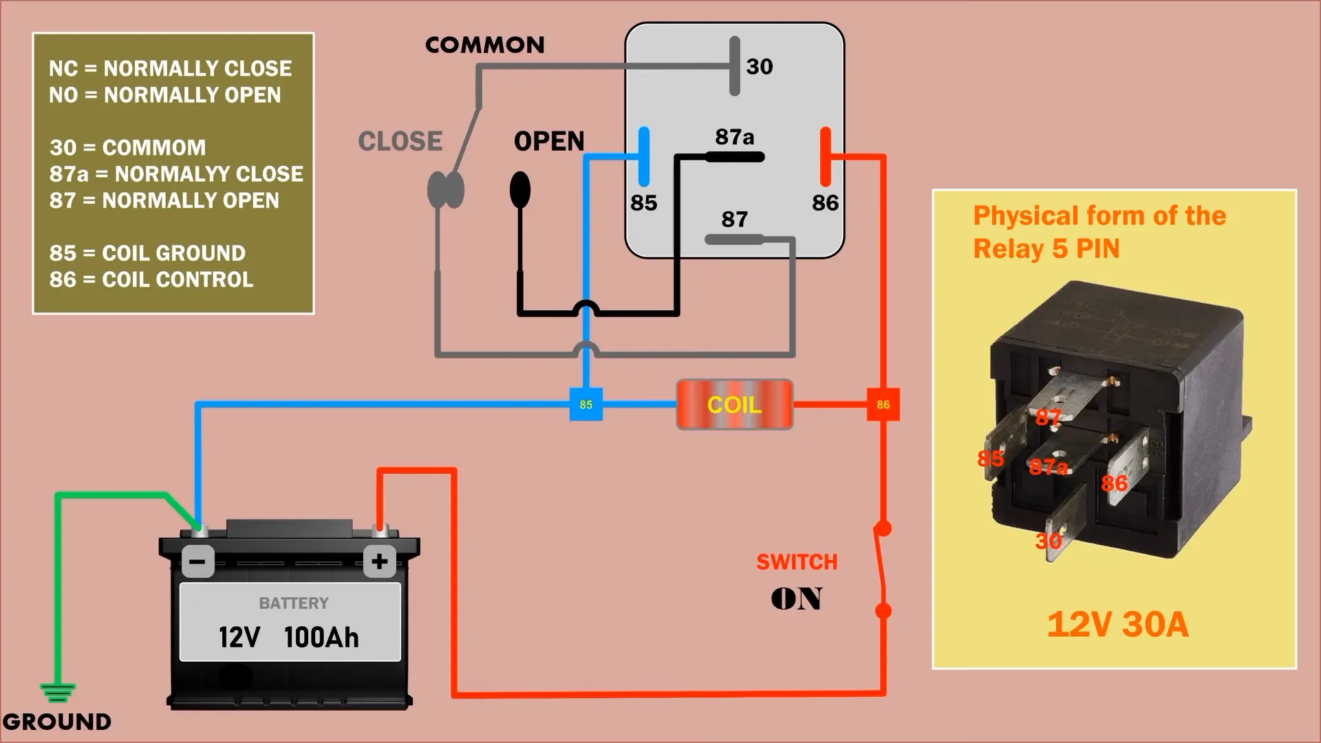
المرحل ذو 5 سنون هو مكون كهربائي متعدد الاستخدامات يستخدم للتحكم في الأجهزة ذات التيار العالي بإشارات منخفضة الطاقة، ويوجد عادةً في أنظمة السيارات، والتشغيل الآلي للمنزل، والآلات الصناعية. يستكشف هذا الدليل الوظائف والتهيئة والتوصيلات المناسبة للمرحلات ذات 5 سنون ويقدم نظرة ثاقبة حول تشغيلها وتطبيقاتها.
تقسيم مكونات المرحل ذو 5 دبابيس
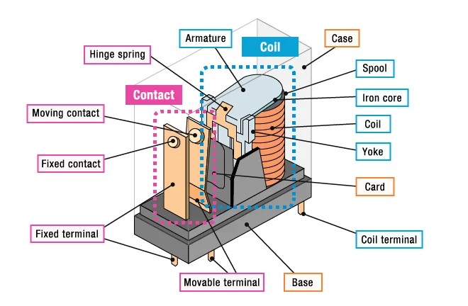
الائتمان إلى أومرون
يتكون المرحل ذو 5 سنون من عدة مكونات رئيسية تعمل معاً لتمكين وظيفة التحويل:
- الملف الكهرومغناطيسي: وهو مصنوع من سلك نحاسي ملفوف حول قلب حديدي، ويولد مجالاً مغناطيسياً عند تنشيطه.
- حديد التسليح: ذراع معدنية متحركة تستجيب للمجال المغناطيسي للملف لتوصيل أو فصل ملامسات المرحل.
- جهات الاتصال: عناصر التبديل، بما في ذلك:
- جهة الاتصال المشتركة (COM): نقطة التوصيل المركزية (الدبوس 30).
- جهة اتصال مفتوحة عادةً (NO): يتصل ب COM عند تنشيطه (السن 87).
- جهة اتصال مغلقة عادةً (NC): متصل ب COM عند إلغاء تنشيطه (السن 87A).
- الربيع: يوفر قوة رجوع لاستعادة المحرك عند إلغاء تنشيط الملف.
- السكن: غلاف واقي، عادةً ما يكون من البلاستيك أو المعدن، يحيط بجميع المكونات الداخلية.
- المحطات الطرفية: المسامير الخارجية الخمسة (85، 86، 30، 87، 87A) للتوصيل بالدوائر الخارجية.
تعمل هذه المكونات معًا لتمكين المرحل من التبديل بين الدوائر، مما يوفر العزل الكهربائي والتحكم في الأحمال ذات التيار العالي بإشارات منخفضة الطاقة.
تكوين دبوس الترحيل
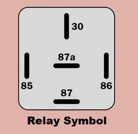
يتكون تكوين المرحل ذو 5 سنون من مجموعتين مختلفتين من السنون:
- سنون اللفائف (85 و86): تعمل هذه على تنشيط المرحل عند تطبيق الجهد، مما يؤدي إلى إنشاء مجال مغناطيسي لتنشيط المفتاح.
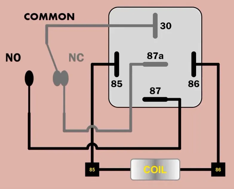
- تبديل الدبابيس (30 و87 و87A): الدبوس 30 هو التلامس المشترك المتصل بمصدر الطاقة، بينما 87 هو التلامس المفتوح عادةً (NO) و87A هو التلامس المغلق عادةً (NC).
عند تنشيطه، يقوم المرحل بتبديل الوصلة من الدبوس 30 إلى 87، مما يسمح بالتحكم في دائرتين مختلفتين. يمكّن هذا الإعداد المرحل من العمل كمفتاح أحادي القطب مزدوج الرمي (SPDT)، مما يوفر تنوعًا في مختلف التطبيقات الكهربائية.
شرح عملية الترحيل
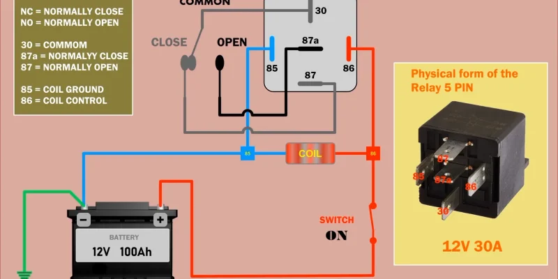
يعتمد تشغيل المرحل ذو 5 سنون على المبادئ الكهرومغناطيسية، مما يسمح له بالتحكم في الدوائر ذات التيار العالي بإشارات منخفضة الطاقة. عندما يتم تطبيق الجهد على دبابيس الملف (85 و86)، فإنه يخلق مجالاً مغناطيسياً يجذب المحرك الداخلي. تؤدي هذه الحركة إلى تبديل التلامس المشترك (السن 30) من موضعه الطبيعي.
في حالة عدم تنشيطه، يتم توصيل الدبوس 30 بالملامس المغلق عادةً (NC) (87A). عندما يتم تنشيط الملف، يتحرك المحرك، مما يؤدي إلى قطع هذا الاتصال وإنشاء اتصال جديد بين السن 30 والتلامس المفتوح عادة (NO) (87). يمكّن إجراء التبديل هذا المرحل من التحكم في دائرتين منفصلتين في وقت واحد.
تعد قدرة المرحل على التعامل مع مستويات الجهد المختلفة بين دوائر التحكم والدوائر المبدلة ميزة رئيسية. على سبيل المثال، يمكن استخدام إشارة بجهد 12 فولت للتحكم في دائرة تعمل بجهد أعلى بكثير، مما يوفر عزلاً كهربائياً وأماناً.
زمن الاستجابة هو جانب آخر حاسم في تشغيل المرحلات. يمكن لمعظم مرحلات السيارات التبديل في غضون 5-10 مللي ثانية، مما يجعلها مناسبة للتطبيقات الحساسة للوقت. ومع ذلك، من المهم ملاحظة أن التبديل المتكرر يمكن أن يؤدي إلى تآكل جهات الاتصال بمرور الوقت.
لحماية المرحل وإطالة عمره، من الشائع استخدام صمام ثنائي عبر دبابيس الملف. هذا المكون، الذي غالباً ما يسمى الصمام الثنائي المرتد الطائر، يمنع طفرات الجهد التي تحدث عندما يتم إلغاء تنشيط الملف، والتي يمكن أن تتلف المكونات الإلكترونية الحساسة في دائرة التحكم.
يعد فهم الميكانيكا الداخلية للترحيل خماسي السنون أمرًا ضروريًا للتنفيذ السليم واستكشاف الأخطاء وإصلاحها. من خلال فهم هذه المبادئ التشغيلية، يمكن للمهندسين والفنيين دمج هذه المكونات متعددة الاستخدامات بفعالية في مجموعة واسعة من الأنظمة الكهربائية، بدءًا من دوائر السيارات البسيطة إلى تطبيقات التحكم الصناعية المعقدة.
تعليمات الأسلاك
لتوصيل مرحل 5 سنون بشكل صحيح، اتبع الخطوات التالية:
- حدد السنون: 30 (مشترك)، و87 (مفتوح عادةً)، و87 أ (مغلق عادةً)، و85 (طاقة الملف)، و86 (تأريض الملف).
- قم بتوصيل الملف عن طريق توصيل سلك من السن 85 بأرضي الدائرة وآخر من السن 86 بمفتاح التحكم أو مصدر الطاقة.
- قم بتوصيل الحمل بالسن 30 (مشترك). بالنسبة للأجهزة التي ينبغي تنشيطها عند تنشيط المرحِّل، وصِّل بالسنّ 87 (NO). بالنسبة للأجهزة التي تظل نشطة عند إيقاف تشغيل المرحِّل، استخدم السنون 87A (NC).
- بعد الانتهاء من التوصيلات، اختبر الإعداد من خلال تطبيق الجهد على أطراف الملف (السنون 85 و86) وتحقق من أن المرحل يقوم بالتبديل بشكل صحيح بين السنون 87 و87A. تأكد من أن جميع التوصيلات آمنة واستخدم أجهزة الحماية المناسبة، مثل الصمامات الثنائية عبر الملف، لمنع ارتفاعات الجهد التي قد تتلف المكونات.
التطبيقات الشائعة
المرحلات ذات 5 سنون هي مكونات متعددة الاستخدامات تستخدم على نطاق واسع في مختلف الأنظمة الكهربائية. وفيما يلي قائمة بالتطبيقات الشائعة:
- أنظمة السيارات:
- التحكم في المصابيح الأمامية، ومصابيح الضباب، والإضاءة المساعدة
- إدارة النوافذ الكهربائية وأنظمة القفل المركزي
- تشغيل مضخات الوقود ومراوح تبريد المحرك
- الآلات الصناعية:
- التحكم في المحركات والمشغلات في معدات التصنيع
- إدارة أقفال السلامة ودوائر التوقف في حالات الطوارئ
- التبديل بين مصادر الطاقة في الأنظمة الاحتياطية
- أتمتة المنزل:
- التحكم في أنظمة التدفئة والتهوية وتكييف الهواء ومنظمات الحرارة
- تشغيل أجهزة فتح أبواب المرآب وأنظمة الأمان
- إدارة الأجهزة المنزلية الذكية وأدوات التحكم في الإضاءة
- توزيع الطاقة:
- عزل الدوائر الكهربائية في اللوحات الكهربائية
- التبديل بين مصادر الطاقة الرئيسية والاحتياطية
- التحكم في أحمال التيار العالي في أنظمة الطاقة الشمسية وطاقة الرياح
تستفيد هذه التطبيقات من قدرة المرحل خماسي السنون على التبديل بين الدوائر، والتعامل مع التيارات العالية، وتوفير العزل الكهربائي، مما يجعله مكونًا أساسيًا في مختلف الأنظمة الكهربائية والإلكترونية.

