Mabilis na Sagot: Paano gumagana ang isang ATS?
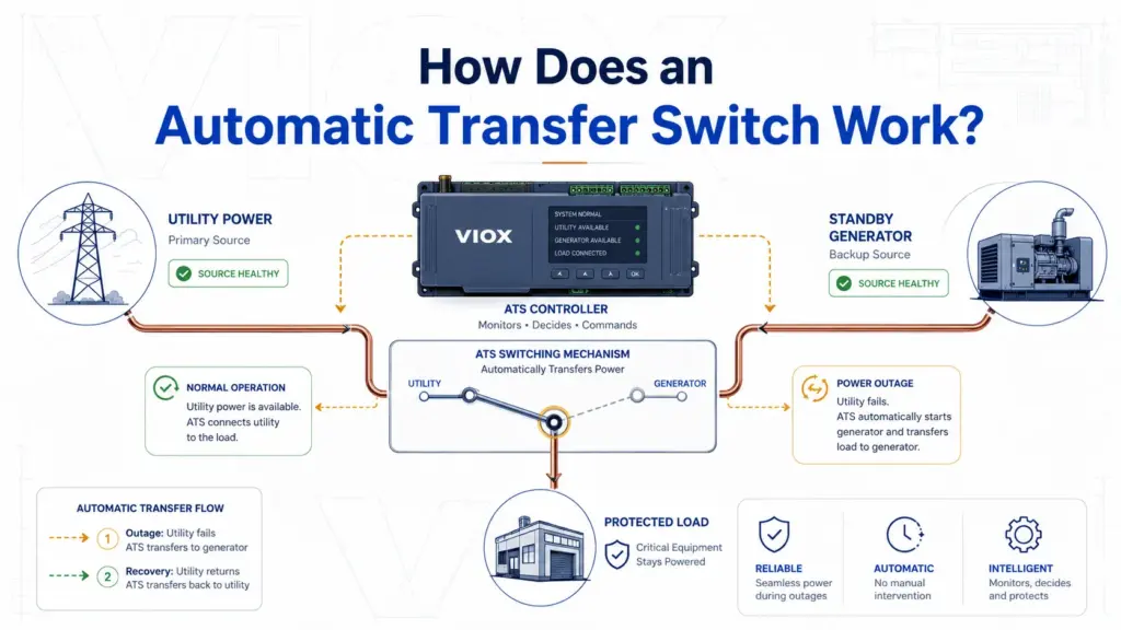
An automatic transfer switch (ATS) gumagana ito sa pamamagitan ng pagsubaybay sa normal na pinagmumulan ng kuryente, pagtukoy kung ang pinagmumulan ay hindi na katanggap-tanggap, pagsisimula o pagsuri sa alternatibong pinagmumulan, paglilipat ng load sa backup na kuryente, at paglilipat muli ng load pabalik kapag bumalik at nanatiling stable ang normal na pinagmumulan.
Sa isang sistemang may generator, ang ATS ay hindi lumilikha ng kuryente. Nagpapasya ito kung aling pinagmumulan ang magbibigay ng kuryente sa load at kinokontrol ang pagkakasunod-sunod ng paglipat upang ang generator, utility supply, at downstream load ay hindi magkamaling magkonekta.
Sa pinakasimpleng pagkakasunod-sunod:
- Minomonitor ng ATS ang normal na source.
- Nabigo ang normal na source o lumampas ito sa mga katanggap-tanggap na limitasyon.
- Naghihintay ang ATS sa loob ng isang naka-program na delay upang maiwasan ang hindi kinakailangang paglipat.
- Nagpapadala ang ATS ng signal para mag-start ang generator o sinusuri nito ang alternatibong source.
- Tinitiyak ng ATS na handa na ang backup source.
- Inililipat ng switching mechanism ang load.
- Minomonitor ng ATS ang pagbabalik ng normal na source.
- Pagkatapos ng stable return delay, ibabalik ng ATS ang load sa normal na power.
- Maaaring magpatuloy ang pagtakbo ng generator para sa cooldown bago ito huminto.
Kung kailangan mo muna ang pangunahing acronym, tingnan ang Kahulugan ng ATS sa Electrical. Ang artikulong ito ay nakatuon sa prinsipyo ng paggana ng ATS, mga panloob na bahagi, at lohika ng pagkakasunod-sunod ng paglipat.
Mga Pangunahing Takeaway
- Ang ATS ay isang device para sa pagpili ng source, hindi ito isang power generator o overcurrent protective device sa sarili nito.
- Sinusubaybayan ng controller ang boltahe, frequency, kondisyon ng phase, mga timer, at availability ng source bago payagan ang paglipat.
- Ang kabuuang oras ng pagpapanumbalik (total restoration time) ay hindi katulad ng oras ng paglipat ng contact (contact switching time). Sa mga sistemang may generator, mahalaga ang delay sa pag-detect, pag-start ng generator, warm-up, pagtanggap sa source, paglipat, at pag-stabilize ng load.
- Ang interlocking ay mahalaga dahil ang normal at alternatibong source ay hindi dapat magkasabay na nakakonekta maliban kung ang system ay partikular na idinisenyo at inaprubahan para sa closed-transition operation.
- Ang open transition, delayed transition, at closed transition ay naglalarawan ng iba't ibang paraan ng paglilipat ng load sa pagitan ng mga source.
- Ang pagpili ng ATS ay dapat isaalang-alang ang uri ng source, tolerance ng load, paraan ng transition, switching architecture, fault-current rating, neutral switching, at protection coordination.
Mga Pangunahing Bahagi ng isang Automatic Transfer Switch
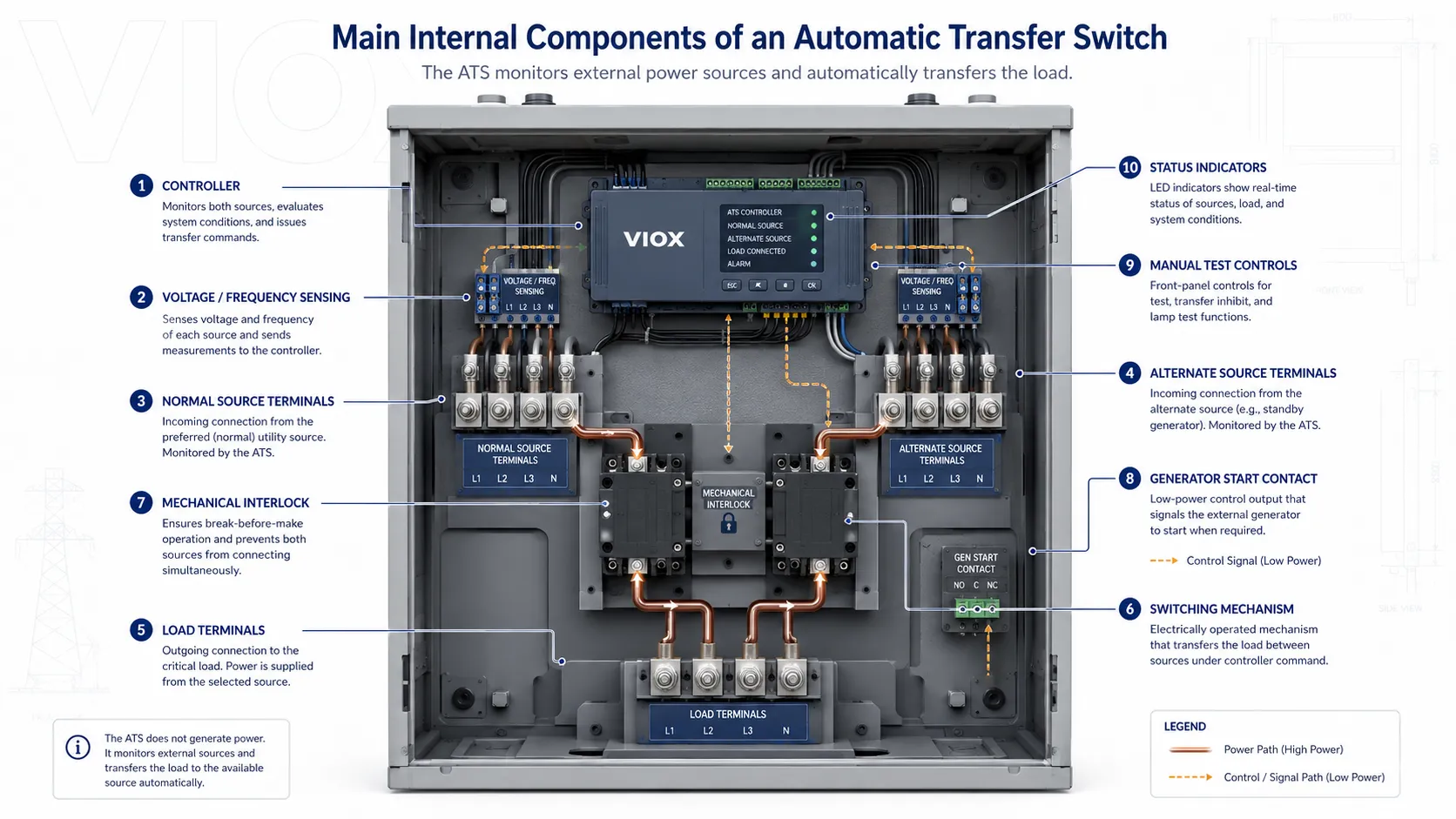
Ang ATS ay hindi lamang isang pares ng power contacts. Ito ay isang coordinated na sistema ng mga bahagi para sa sensing, control, switching, at interlocking.
| Bahagi | Ano ang ginagawa nito | Bakit ito mahalaga |
|---|---|---|
| Controller | Sinusubaybayan ang boltahe ng source, frequency, kondisyon ng phase, mga timer, alarm, at transfer logic | Nagpapasya kung kailan pinapayagan ang transfer at retransfer |
| Circuit para sa pag-detect ng boltahe at frequency | Sinusuri kung katanggap-tanggap ang normal at alternatibong source | Pinipigilan ang paglipat sa hindi stable o pumalyang kuryente |
| Mekanismo ng paglipat | Pisikal na ikinakabit ang load sa isa sa mga source | Dinadala ang load current at isinasagawa ang pagpapalit ng source |
| Mechanical o electrical interlock | Pinipigilan ang sabay na pagdaloy ng kuryente mula sa dalawang source patungo sa load sa mga open-transition system | Nakakatulong upang maiwasan ang backfeed at hindi sinasadyang pag-parallel |
| Mga power terminal | Ikonekta ang normal na source, alternatibong source, at load | Dapat tumugma sa mga kinakailangan para sa current, boltahe, pole, at wiring |
| Generator start contact | Nagpapadala ng dry-contact o control signal sa generator controller | Nagbibigay-daan sa awtomatikong standby operation |
| Mga manual na kontrol at indicator | Nagbibigay ng test, manual na operasyon, status ng source, at impormasyon ng alarm | Sumusuporta sa commissioning at maintenance |
| Interface ng proteksyon | Nakikipag-ugnayan sa mga upstream breaker, fuse, o mga disenyong nakabase sa integrated breaker kung naaangkop | Ang paglilipat ng source at proteksyon sa overcurrent ay magkahiwalay na usapin sa disenyo |
Ang controller ang nagpapasya kung kailan dapat mangyari ang paglilipat. Ang switching mechanism ang nagsasagawa nito kung paano Ang load ay inililipat sa pagitan ng mga source.
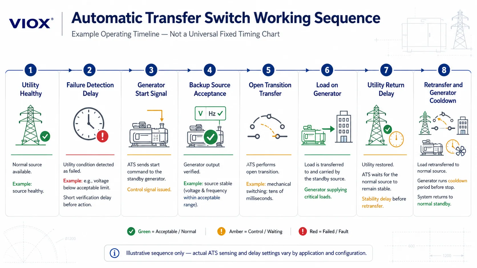
Talahanayan ng Pagkakasunod-sunod ng Paggana ng ATS
| Step | Ano ang ginagawa ng ATS | Bakit ito mahalaga |
|---|---|---|
| 1 | Sinusubaybayan ang boltahe at frequency ng normal na source | Iniiwasan ang hindi kinakailangang paglipat kapag maayos ang supply ng kuryente mula sa utility |
| 2 | Kinukumpirma ang pagkawala ng kuryente pagkatapos ng nakaprogramang delay | Pinipigilan ang maling paglipat sa panahon ng panandaliang pagbaba ng boltahe o aberya sa linya |
| 3 | Nagpapadala ng signal para mag-start ang generator o sinusuri ang alternatibong source | Inihahanda ang backup power bago ang paglilipat ng load |
| 4 | Sinusuri ang boltahe, frequency, at katatagan ng backup source | Pinipigilan ang paglipat sa hindi matatag na kuryente |
| 5 | Inililipat ang load ayon sa uri ng transition | Ibinabalik ang supply mula sa backup source |
| 6 | Binabantayan ang pagbabalik ng normal na source | Inihahanda ang retransfer kapag stable na ang kuryente mula sa utility |
| 7 | Muling paglilipat pagkatapos ng stable return delay | Iniiwasan ang paulit-ulit na paglipat habang hindi stable ang pagbabalik ng kuryente |
| 8 | Pinapatakbo ang generator cooldown, kung naka-configure | Hinahayaan ang generator na maging stable ang temperatura bago ito patayin |
Ito ang pinakakaraniwang lohika para sa ATS na may generator. Ang eksaktong timing, mga threshold, at gawi ng kontrol ay nakadepende sa ATS controller, generator controller, pamantayan ng proyekto, uri ng source, at disenyo ng system.
Paghihiwalay ng Timing ng ATS: Switching Time kumpara sa Total Restoration Time

Ang isang karaniwang maling akala ay ang pagtrato sa ATS transfer time bilang isang solong numero. Sa katotohanan, ang kabuuang outage o restoration sequence ay maaaring maglaman ng ilang magkakahiwalay na delay.
| Timing item | Kahulugan nito | Karaniwang tala sa disenyo |
|---|---|---|
| Pagkaantala sa pagtukoy ng pagkasira | Oras na ginagamit upang kumpirmahin na ang normal na source ay talagang hindi katanggap-tanggap | Kadalasang naa-adjust mula sa bahagi ng isang segundo hanggang ilang segundo upang maiwasan ang paglipat sa panahon ng panandaliang pagbaba ng boltahe |
| Oras ng pagsisimula ng generator | Oras para sa makina ng generator na umandar at maabot ang bilis ng operasyon | Nalalapat lamang kapag ang alternatibong source ay isang standby generator; ito ang karaniwang pinakamahabang bahagi ng oras ng outage |
| Pagkaantala sa pagtanggap ng source (Source acceptance delay) | Oras na ginagamit upang kumpirmahin na ang backup voltage at frequency ay stable | Maraming controller ang naghahanap ng boltahe na malapit sa nominal at frequency na nasa loob ng limitadong band bago tanggapin ang source |
| Oras ng mekanikal na paglipat (Mechanical switching time) | Oras para sa mga contact o mekanismo ng ATS upang lumipat sa pagitan ng mga source | Ang paggalaw ng contact sa open-transition ay karaniwang nasa sampu-sampung millisecond; maraming mekanikal na ATS device ang nasa humigit-kumulang 40-100 ms na range, ngunit ang data sheet ang dapat sundin |
| Pagkaantala sa paglipat pabalik (Retransfer delay) | Oras na ginagamit upang kumpirmahin ang pagbabalik ng kuryente mula sa utility bago lumipat pabalik | Kadalasan ay mas matagal kaysa sa paunang pagkaantala ng paglipat upang maiwasan ang paulit-ulit na paglipat habang hindi pa stable ang pagbabalik ng kuryente mula sa utility |
| Pagpapalamig ng generator (cooldown) | Oras ng pagtakbo nang walang load pagkatapos ng paglipat pabalik | Kadalasan ay ilang minuto sa mga sistemang may backup na generator, depende sa mga setting ng controller ng generator |
Sa mga regulated na emergency power system, maaaring mangailangan ang mga detalye ng proyekto ng pagpapanumbalik ng load sa loob ng isang tinukoy na time class. Sa maraming standby system na may backup na generator, ang buong pagkakasunod-sunod ay sinusukat sa mga segundo, habang ang mismong paggalaw ng mekanikal na contact ay maaaring masukat sa mga millisecond. Palaging i-verify ang kinakailangang timing laban sa pamantayan ng proyekto, lokal na code, at mga data sheet ng ATS/generator.
Para sa isang dedikadong paliwanag tungkol sa bilis ng paglipat (transfer speed), tingnan ang Paliwanag sa Oras ng Paglipat ng ATS.
Pagsubaybay sa Normal na Power
Sa panahon ng normal na operasyon, pinapanatili ng ATS ang load na nakakonekta sa preferred o normal na source, na karaniwang ay utility power. Patuloy na sinusubaybayan ng controller ang mga kondisyon ng source gaya ng:
- pagkakaroon ng boltahe
- under-voltage
- over-voltage
- pagkawala ng phase
- pagkakasunod-sunod ng phase kung naaangkop
- frequency
- timer para sa katatagan ng source
Hindi dapat mag-transfer ang ATS dahil lamang sa panandaliang pagkurap ng boltahe. Karamihan sa mga system ay gumagamit ng naka-program na time delay bago ideklarang may failure ang normal na source. Pinipigilan nito ang hindi kinakailangang pag-start ng generator at hindi kinakailangang pag-transfer ng load na dulot ng panandaliang pagbaba ng boltahe, mga event sa pag-switch ng utility, pag-start ng motor, o mga panandaliang aberya.
Pagtukoy sa Pagkasira ng Utility (Utility Failure Detection)
Kapag ang normal na source ay naging hindi katanggap-tanggap, sisimulan ng ATS controller ang logic nito para sa failure. Ang "failure" ay hindi laging nangangahulugan ng kabuuang blackout. Maaari rin itong mangahulugan ng:
- boltahe na mas mababa sa naka-program na katanggap-tanggap na limitasyon, na karaniwang nasa 80-90% ng nominal sa maraming komersyal na standby application
- nawawalang phase
- malalang imbalance sa boltahe
- hindi katanggap-tanggap na frequency, halimbawa ay ilang hertz ang layo mula sa nominal depende sa mga setting ng controller at tolerance ng load
- maling pagkakasunod-sunod ng phase sa mga three-phase system
- kawalan ng katatagan ng source na tumatagal nang higit sa naka-program na delay
Dapat matukoy ng ATS ang pagkakaiba sa pagitan ng totoong pagkasira ng source at ng panandaliang aberya. Ito ang dahilan kung bakit mahalaga ang failure-confirmation timer. Kung masyadong maikli ang delay, maaaring magkaroon ng nuisance-transfer ang system. Kung masyadong mahaba naman ang delay, maaaring manatiling walang sapat na kuryente ang load nang mas matagal kaysa sa kinakailangan.
Ang mga numerong ito ay hindi unibersal na mga panuntunan. Ang mga threshold ng boltahe at frequency ay karaniwang programmable o partikular sa produkto, at dapat itong itakda ayon sa load, kakayahan ng generator, mga kinakailangan ng proyekto, at mga naaangkop na electrical standard sa halip na kopyahin lamang mula sa ibang instalasyon.
Generator Start Signal / Kahilingan para sa Alternate Source
Sa isang standby generator system, karaniwang nagpapadala ang ATS ng start signal sa generator controller pagkatapos makumpirma ang pagkawala ng kuryente mula sa utility. Karaniwan itong ginagawa sa pamamagitan ng generator start contact o control circuit, at hindi sa pamamagitan ng direktang paglipat ng output power ng generator.
Sa puntong ito, hindi pa handa ang ATS na ilipat ang load. Dapat munang gawin ng generator ang mga sumusunod:
- matagumpay na mag-start
- bumuo ng output voltage
- maabot ang katanggap-tanggap na frequency
- maging stable sa loob ng mga limitasyon ng controller, kadalasan sa loob ng mas mahigpit na band kumpara sa paunang threshold ng pagkasira
- matugunan ang anumang naka-program na warm-up o delay sa pagtanggap ng source
Para sa mga sistemang walang generator, ang parehong lohika ay nalalapat pa rin sa ibang anyo. Ang alternatibong source ay maaaring pangalawang utility feeder, output ng inverter, source na may backup na UPS, o iba pang distribution path. Dapat pa ring kumpirmahin ng ATS na ang alternatibong source ay katanggap-tanggap bago ang paglipat.
Handa na ang Backup Source
Bago ang paglipat, dapat kumpirmahin ng ATS na ang alternatibong source ay katanggap-tanggap. Ang paglipat sa isang mahina o hindi stable na generator ay maaaring magdulot ng pagkasira ng load, paghinto ng motor, pagbitaw ng contactor, mga problema sa control power, o hindi kinakailangang stress sa kagamitan.
Maaaring suriin ng controller ang mga sumusunod:
- boltahe ng alternatibong pinagmumulan
- dalas ng alternatibong pinagmumulan
- pagkakaroon ng phase
- pagkakasunod-sunod ng phase
- katatagan ng pinagmumulan sa paglipas ng panahon
- hudyat ng kahandaan mula sa generator controller
Pagkatapos lamang na maging katanggap-tanggap ang alternatibong pinagmumulan magsisimula ang ATS sa paglilipat ng load. Sa praktikal na aplikasyon, maaaring tanggihan ng controller ang isang generator na nagsimula na ngunit nasa labas pa rin ng window ng pagtanggap para sa boltahe o dalas nito. Halimbawa, ang isang generator na malapit na sa rated voltage ngunit nagbabago pa ang dalas ay hindi dapat ituring na handa para sa mga sensitibong load.
Pagkakasunod-sunod ng Paglilipat ng Load
Ang aktwal na paglilipat ay nakadepende sa uri ng transition ng ATS at mekanismo ng paglipat. Para sa maraming sistemang may generator, ang karaniwang paraan ay open transition, na tinatawag ding break-before-make. Dinidiskonekta ng ATS ang load mula sa normal na source bago ito ikonekta sa alternatibong source.
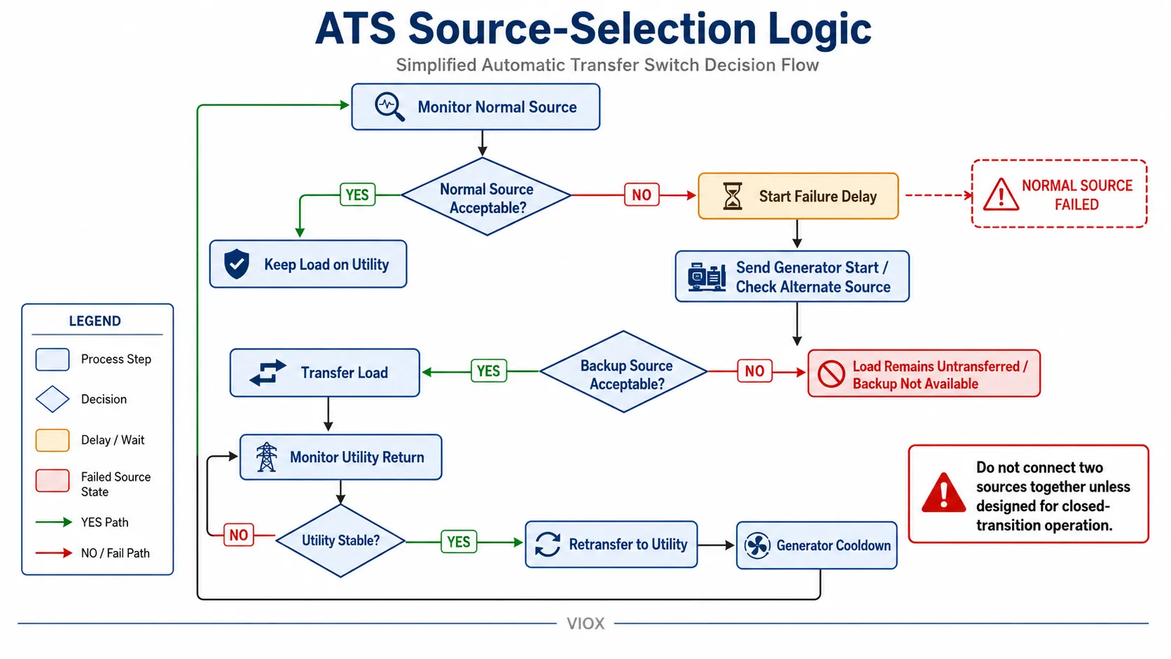
Sa isang pinapayak na pagkakasunod-sunod ng open-transition:
- Kinukumpirma na hindi katanggap-tanggap ang normal na source.
- Kinukumpirma na katanggap-tanggap ang alternatibong source.
- Bumubukas ang mga contact ng normal na source.
- Pinipigilan ng isang interlocked na mekanismo na magkasabay na magsara ang dalawang source.
- Magsasara ang mga contact ng alternatibong source.
- Ang load ay sinusuplayan ng backup source.
Ang pangunahing layunin sa kaligtasan ay ang paghihiwalay ng mga source. Dapat pigilan ng ATS ang backfeeding mula sa generator patungo sa utility at iwasan ang hindi sinasadyang pag-parallel maliban kung ang kagamitan at sistema ay partikular na idinisenyo para sa closed-transition operation.
Ang pisikal na switching interval ay isang bahagi lamang ng buong proseso. Maaaring mabilis ang paggalaw ng contact ng isang produkto, ngunit nararanasan pa rin ng load ang buong pagkakasunod-sunod: detection delay, pagsisimula o pag-validate ng source, pagtanggap sa source, mekanikal na paglipat, at pagbawi ng load.
Para sa mas malalim na detalye tungkol sa uri ng transition, tingnan ang Gabay sa Pagpili ng Open vs Closed Transition ATS. Ang artikulong ito ay nakatuon lamang sa pangkalahatang pagkakasunod-sunod ng operasyon.
Operasyon gamit ang Backup Power
Pagkatapos ng paglipat, ang load ay tatakbo mula sa alternatibong source. Hindi titigil ang ATS sa pagsubaybay. Patuloy nitong babantayan ang magkabilang panig:
- katatagan ng backup na pinagmumulan ng kuryente
- pagbabalik sa normal na pinagmumulan ng kuryente
- mga alarma ng controller
- posisyon ng paglilipat
- opsyonal na generator o mga signal para sa remote monitoring
Kung ang backup na pinagmumulan ng kuryente ay hindi na katanggap-tanggap, ang susunod na aksyon ay nakadepende sa disenyo ng system. Ang ilang system ay maaaring mag-alarma, magbawas ng load, sumubok na maglipat muli kung bumalik na ang utility, o manatili sa posisyon hanggang sa may gawing maintenance.
Paglilipat Muli Kapag Bumalik ang Utility
Kapag bumalik ang kuryente mula sa utility, ang ATS ay karaniwang hindi agad lumilipat pabalik. Ginagamit ang stable return delay upang kumpirmahin na tunay na nakabawi na ang normal na pinagmumulan ng kuryente.
Ang pagkakasunod-sunod ng retransfer ay karaniwang gumagana nang ganito:
- Natutukoy ng ATS na bumalik na ang kuryente mula sa utility.
- Sinusuri ng controller kung katanggap-tanggap ang boltahe at frequency.
- Tumatakbo ang isang naka-program na return delay.
- Inililipat ng ATS ang load pabalik sa normal na source.
- Patuloy na tatakbo ang generator nang walang load para sa cooldown kung ito ay naka-configure.
- Nagpapadala ang ATS ng signal para huminto ang generator pagkatapos ng cooldown.
Iniiwasan nito ang paulit-ulit na paglipat at pag-retransfer habang hindi pa stable ang pagbabalik ng kuryente mula sa utility.
Open Transition vs Closed Transition vs Delayed Transition
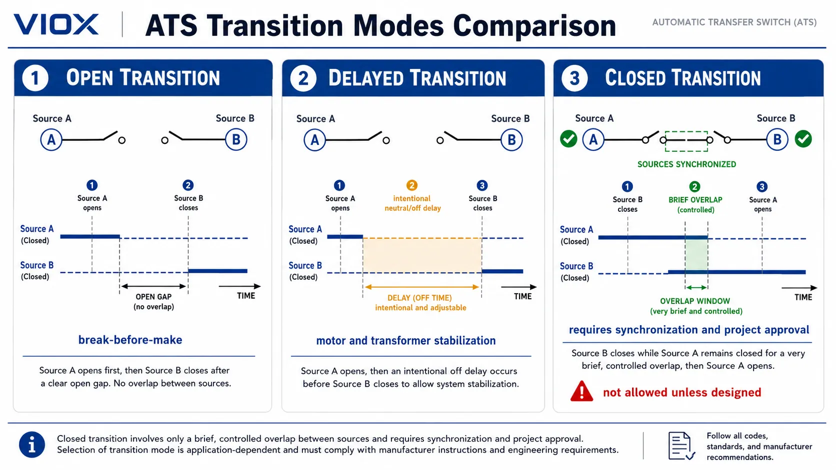
Inilalarawan ng uri ng transition ng ATS ang nangyayari sa kuryente habang nagpapalit ng source.
| Uri ng transition | Paano ito gumagana | Karaniwang gamit |
|---|---|---|
| Open transition | Pinuputol ang koneksyon mula sa isang source bago ikonekta sa isa pa | Karamihan sa mga standby generator transfer system |
| Delayed transition | Nagdaragdag ng sinadyang neutral/off time sa pagitan ng mga source | Mga motor, transformer, residual voltage decay, load stabilization |
| Closed transition | Pansamantalang pinagsasabay ang dalawang katanggap-tanggap na synchronized source | Nakaplano na paglilipat o muling paglilipat kung saan dapat mabawasan ang pagkakaantala |
Ang closed transition ay hindi katulad ng UPS at hindi dapat ituring na pangkalahatang solusyon para sa walang-patid na kuryente. Kinakailangan nito na ang parehong source ay katanggap-tanggap at naka-synchronize, at maaaring mangailangan ng pag-apruba mula sa utility depende sa proyekto.
Para sa detalyadong pagpili, gamitin ang nakalaang Gabay sa Pagpili ng Open vs Closed Transition ATS.
PC Class kumpara sa CB Class ATS
Ang switching element sa loob ng ATS ay nakakaapekto sa proteksyon, tibay, at koordinasyon ng system.
Sa terminolohiya ng IEC transfer-switching, ang automatic transfer switching equipment ay karaniwang tinatalakay kaugnay ng klase sa PC at CB class sa ilalim ng IEC 60947-6-1. Sa konteksto ng North America, ang transfer switch equipment ay karaniwang sinusuri sa ilalim ng UL 1008.
| Arkitektura ng ATS | Pangunahing konsepto | Praktikal na implikasyon |
|---|---|---|
| PC-class na ATS | Kagamitang pang-transfer switching na sadyang ginawa para sa paggawa, pagdadala, at paglilipat ng kuryente | Karaniwang compact at optimized para sa transfer duty; ang panlabas na overcurrent protection ay karaniwang pinag-uugnay nang hiwalay |
| CB-class na ATS | Kagamitang pang-transfer switching na nakabase sa mga circuit-breaker switching device | Maaaring sumuporta sa mga function ng proteksyon at isolation depende sa disenyo at koordinasyon ng breaker |
| ATS na nakabase sa contactor | Gumagamit ng mga mekanismong contactor na kontrolado ng kuryente | Karaniwan sa ilang compact o lower-current na mga system, ngunit hindi dapat awtomatikong ituring na IEC CB class |
| Motor-operated transfer switch | Gumagamit ng mekanikal na changeover mechanism na pinapatakbo ng motor | Karaniwan sa dual-power transfer equipment at mas malalaking mechanical transfer system |
Ang seksyong ito ay sadyang maikli dahil ang pagpili sa pagitan ng PC at CB ay isang hiwalay na paksa. Para sa mas malalim na paghahambing, tingnan ang Gabay sa Pagpili ng PC Class vs CB Class ATS.
Konteksto ng mga Pamantayan at Pagsunod
Ang iba't ibang merkado ay gumagamit ng iba't ibang pamantayan para sa transfer switching equipment at emergency power systems. Ang talahanayan sa ibaba ay isang praktikal na gabay lamang at hindi kapalit ng pagsusuri sa lokal na code.
| Pamantayan o framework | Karaniwang kaugnayan | Ano ang naaapektuhan nito |
|---|---|---|
| IEC 60947-6-1 | Automatic transfer switching equipment sa mga pamilihang nakabase sa IEC | Klasipikasyon ng ATSE, mga kinakailangan sa pagganap, pagmamarka, balangkas ng pagsubok |
| UL 1008 | Transfer switch equipment sa mga aplikasyon sa Hilagang Amerika | Pagsusuri ng transfer switch equipment, mga rating, pagganap sa withstand/closing, pagiging angkop sa pag-install |
| NFPA 110 | Mga emergency at standby power system sa Estados Unidos | Klasipikasyon ng emergency power system, pagsubok, pagpapanatili, at inaasahang oras ng paglipat kung naaangkop |
| Lokal na electrical code | Mga panuntunan sa pag-install na partikular sa bansa o proyekto | Earthing, neutral switching, overcurrent protection, mga pag-apruba, at mga kinakailangan sa pagpapanatili |
Huwag ipagpalagay na ang isang timing value, uri ng transition, o klase ng ATS ay katanggap-tanggap sa lahat ng lugar. Ang mga ospital, data center, planta ng industriya, komersyal na gusali, at mga generator room ay maaaring gumamit ng magkakaibang espesipikasyon ng proyekto.
Ang pinakamadaling paraan upang maunawaan ang lohika ng ATS ay sa pamamagitan ng timeline:
Utility Healthy -> Failure Detection Delay -> Generator Start -> Source Acceptance -> Open Transition Transfer -> Utility Return Delay -> Retransfer -> Generator CooldownMga Karaniwang Maling Pag-unawa Tungkol sa Operasyon ng ATS
Ang ATS ay hindi gumagawa ng backup na kuryente.
Ang ATS ay naglilipat lamang ng load sa pagitan ng mga source. Ang generator, inverter, utility service, o UPS ang nagbibigay ng kuryente.
Ang switching time ng ATS ay hindi ang kabuuang oras ng pagkawala ng kuryente.
Ang kabuuang oras ng pagkawala ng kuryente ay maaaring kabilangan ng pagtukoy sa pagkasira ng source, programmed delay, pag-start ng generator, warm-up, oras ng paglipat, at pag-stabilize ng load.
Ang mas mabilis na paglipat ay hindi laging mas mabuti.
Ang mga motor load, transformer load, at hindi matatag na source ay maaaring mangailangan ng sadyang pagkaantala o delayed transition. Ang bilis ay isa lamang sa mga salik sa disenyo.
Ang closed-transition ATS ay hindi laging proteksyon laban sa pagkawala ng kuryente.
Ang closed transition ay maaaring magbawas o mag-alis ng pagkaantala sa panahon ng nakaplanong paglipat o paglipat pabalik kapag ang parehong source ay katanggap-tanggap at naka-synchronize. Hindi nito magagawang magamit ang isang sirang utility source sa panahon ng aktwal na blackout.
Ang ATS ay hindi katulad ng STS
Ang static transfer switch (STS) ay gumagamit ng electronic switching at ginagamit para sa napakabilis na paglipat sa pagitan ng mga available na source. Ang karaniwang ATS ay kadalasang gumagamit ng mechanical switching. Para sa hangganan, tingnan ang Automatic Transfer Switch ATS kumpara sa Static Transfer Switch STS.
Ang closed transition ay hindi pinapayagan sa lahat ng lugar bilang default
Ang closed transition ay maaaring pansamantalang mag-parallel ng mga source, kaya ang synchronization, mga kontrol, mga kinakailangan ng proyekto, at mga panuntunan ng utility ay dapat suriin.
Paano Piliin ang Tamang Working Logic ng ATS
Bago pumili ng ATS, kumpirmahin ang operating sequence na talagang kailangan mo:
| Tanong sa disenyo | Bakit ito mahalaga |
|---|---|
| Ang alternate source ba ay isang generator, UPS, inverter, grid source, o isa pang feeder? | Magkaiba ang lohika ng kahandaan ng source |
| Gaano katagal kayang tiisin ng load ang pagkaputol ng kuryente? | Tinutukoy nito kung sapat na ang mekanikal na ATS o kung kailangan ng suporta mula sa UPS/STS |
| May mga motor o transformer ba na nakakonekta? | Ang delayed transition ay maaaring makabawas sa mekanikal at elektrikal na stress |
| Pinapayagan ba ang pag-parallel ng mga source? | Ang closed transition ay nangangailangan ng synchronization at pag-apruba |
| Kailangan ba ng ATS ang kontrol para sa pag-start at pag-cooldown ng generator? | Kinakailangan para sa maraming standby generator system |
| Ang overcurrent protection ba ay integrated o external? | Nakakaapekto sa arkitektura ng PC/CB at upstream protection |
| Kailangan ba ng system ng load shedding o priority circuits? | Nakakaapekto sa disenyo ng controller at panel |
| Kailangan bang i-switch ang neutral? | Depende sa grounding system, mga panuntunan sa separately derived source, at lokal na code |
Para sa mas malawak na sourcing at mga paksa sa paghahambing, tingnan ang Manual vs Automatic Transfer Switch at Kailan mo dapat gamitin ang manual transfer switch sa halip na ATS?.
FAQ
Paano gumagana ang isang automatic transfer switch?
Ang isang automatic transfer switch ay nagbabantay sa normal na pinagmumulan ng kuryente, natutukoy kung ito ay hindi na katanggap-tanggap, pinapaandar o tinitiyak ang alternatibong pinagmumulan, inililipat ang load sa backup power, at ibinabalik ito kapag ang normal na pinagmumulan ay bumalik at nanatiling stable.
Pinapaandar ba ng ATS ang generator?
Sa maraming standby generator system, oo. Nagpapadala ang ATS ng start signal sa generator controller pagkatapos makumpirma ang pagkawala ng kuryente mula sa utility. Kailangan pa ring umandar, bumuo ng boltahe, at maging stable ang generator bago ilipat ng ATS ang load.
Agaran ba ang paglipat ng ATS?
Karaniwan ay hindi. Ang isang mechanical ATS ay may source detection, programmed delays, generator start time, source stabilization, at mechanical switching time. Ang kabuuang oras ng pagbabalik ng kuryente ay iba sa oras ng paglipat ng device.
Gaano katagal bago makapaglipat ng kuryente ang isang ATS?
Depende ito sa system. Ang mechanical transfer ay maaaring napakabilis, ngunit ang system na may generator ay maaaring magsama ng detection delay, pag-start ng generator, warm-up, source acceptance, at programmed transfer delay. Ang mga emergency system ay maaaring may mga requirement sa oras na partikular sa proyekto, kaya laging suriin ang naaangkop na standard at data sheet ng kagamitan.
Ano ang mangyayari kapag bumalik ang kuryente mula sa utility?
Minomonitor ng ATS ang bumabalik na utility source. Matapos manatiling stable ang source sa loob ng programmed return delay, ililipat ng ATS ang load pabalik sa utility at maaaring hayaang tumakbo ang generator nang walang load para sa cooldown bago ito patayin.
Maaari bang gumana ang ATS nang walang generator?
Oo. Ang ATS ay maaaring maglipat sa pagitan ng mga utility feed, inverter output, UPS-backed source, o iba pang alternatibong source kung ang kagamitan ay rated at naka-configure para sa application na iyon. Ang hakbang para sa pag-start ng generator ay hindi lamang ginagamit o pinapalitan ng logic para sa pagiging handa ng alternatibong source.
Maaari bang ikonekta ng ATS ang generator at utility nang sabay?
Karamihan sa mga standby ATS system ay gumagamit ng open transition at hindi pinagsasama ang generator at utility. Ang mga closed-transition system ay maaaring pansamantalang mag-parallel ng mga synchronized source na katanggap-tanggap, ngunit kung pinapayagan lamang ito ng kagamitan, controls, mga panuntunan ng utility, at disenyo ng proyekto.
Ano ang prinsipyo ng paggana ng ATS sa isang pangungusap?
Ang prinsipyo ng paggana ng ATS ay ang awtomatikong pagpili ng source: pagsubaybay sa kalusugan ng source, pag-verify sa kahandaan ng backup, ligtas na paglipat ng load, at pagbalik sa gustong source kapag ito ay stable na.
Buod
Ang automatic transfer switch ay gumagana sa pamamagitan ng paggawa ng kontroladong desisyon sa source. Sinusubaybayan nito ang normal na kuryente, kinukumpirma ang pagkawala nito, humihiling o sinusuri ang backup power, tinitiyak ang kahandaan ng source, inililipat ang load, sinusubaybayan ang pagbalik ng utility, at ibinabalik ang load pagkatapos ng stable na recovery.
Ang mahalagang punto ay ang operasyon ng ATS ay isang pagkakasunod-sunod, hindi isang simpleng paggalaw ng switch. Ang tamang pagpili ng ATS ay nakadepende sa load tolerance, uri ng source, paraan ng transition, logic ng pagsisimula ng generator, switching architecture, neutral switching, fault-current rating, at protection coordination.
