周二下午3点47分。您走进厨房,发现冰箱停止运转。悄无声息。您检查配电箱——所有断路器都处于正常闭合状态。您仍将冰箱对应的断路器关闭后重新合上。毫无反应。彻底瘫痪。.
次日早晨,暖通空调技师上门,拆下压缩机外壳,摇头宣布诊断结果:“压缩机烧毁了。绕组已碳化。更换费用1,850美元,另加工时费。您的冰箱已使用十二年——或许该考虑整体更换了。总费用约3,200美元。”
您提出了那个揭示本质的问题:“但为什么断路器没有跳闸?”
“因为,”他解释道,“断路器只针对过电流提供保护。这次故障源于电压过低。可能是昨天暴风雨期间的电压骤降。您的压缩机持续尝试启动,在低电压下无法产生足够扭矩,三十秒内持续抽取过量电流导致过热。等到故障发生时,损害早已形成。”
您的断路器完美履行了设计职能——在电流超限时跳闸。但电压骤降并不总能迅速产生足以触发跳闸的过电流。它们产生的电流刚好足以缓慢"烹煮"您的设备。这就是 **电压盲区**——全面的过电流保护(断路器、保险丝)与零电压事件保护的结合缺失。在典型住宅区,电压扰动每年发生10至40次,无论供电网络看起来多么稳定。.
**快速解答:过欠压保护器的实际功能**
过欠压保护器是一种监测装置,持续测量供电电压,当电压超出安全范围(过高或过低)时自动切断设备电源。待电压恢复正常并稳定预设时长(通常30秒至3分钟)后,该装置将自动恢复供电。.
以下是多数业主和电工忽略的关键区别: 断路器和保险丝响应的是**过量电流**. 。电压保护器响应的是**异常电压** **与电流无关**. 。将120V电路电压降至85V的电压骤降,可能数分钟内都无法产生足以触发15A或20A断路器的额外电流——但电机绕组和电子元件会立即开始受损。设定最低102V(120V的85%)的电压保护器将在0.5至2秒内切断电源,完全避免损害。.
**过欠压保护器与其他常见保护装置有何不同?**
| **保护装置** | **检测对象** | **触发条件** | **预防项目** | **防护盲区** | --- | --- | --- | --- | --- | **断路器** | 过电流 | 电流超额定值 | 导线过热、短路 | 电压骤降、欠压、持续过压 | **浪涌保护器(MOV)** | 电压尖峰 | 瞬态电压尖峰(>330V) | 雷击浪涌、开关瞬变 | 持续欠压/过压、电压骤降、悬浮零线 | **漏电保护器(GFCI)** | 接地故障电流 | 火线零线电流失衡 | 接地故障触电 | 所有电压问题 |
|---|---|---|---|---|
| เบรกเกอร์ | **过欠压保护器** | 异常电压 | 电压超出设定范围 | 电压骤降损害、持续过压、零线断路 | 过电流故障(需断路器配合)、短暂瞬变 | 注意到盲区了吗?您的断路器无法识别电压异常。您的浪涌保护器仅能捕捉瞬时尖峰。两者都无法防护30秒电压骤降导致的渐进性损伤,或是132V持续过压对设备的无声损耗。这正是过欠压保护器的价值所在。 | 这类装置亦称作自动电压切换器(AVS)、电压监测器或电压保护继电器。在住宅及轻型商业场所中,它们通常保护独立电路(空调、冰箱)、电器负载或整个子配电箱。安装简便——多数型号与负载串联安装(介于断路器与设备之间),并配备可调电压阈值与重接延时设置。 | **电压盲区:为何断路器无法识别电压问题** |
| 打开任何住宅配电箱,您都能看到完备的过电流保护:按导线载流量匹配的断路器(14号线配15A、12号线配20A、10号线配30A),浴室厨房的漏电保护,卧室可能配备的电弧故障保护。电流保护体系通常坚实可靠。但若问及电压保护,往往只有沉默。 | ——多数住宅对一种故障模式(过电流)进行了 exhaustive 防护,却让电器电子设备完全暴露在另一种同样具有破坏性的故障模式(异常电压)中。人们默认断路器能处理"所有问题"。实则不然。 | **住宅电力系统中电压事件的成因** | 电压扰动主要源于以下三种情况,且均不会产生足以触发断路器跳闸的过电流: | 电压骤降与欠压: |
| เบรกเกอร์ GFCI | กระแสไฟฟ้ารั่วลงดิน | ความไม่สมดุลระหว่างสายไฟและสายนิวทรัล | ไฟฟ้าดูดจากไฟฟ้ารั่วลงดิน | ปัญหาแรงดันไฟฟ้าทั้งหมด |
| อุปกรณ์ป้องกันแรงดันไฟฟ้าเกิน/ต่ำ | แรงดันไฟฟ้าผิดปกติ | แรงดันไฟฟ้าที่อยู่นอกช่วงที่กำหนด | ความเสียหายจากไฟตก, แรงดันไฟฟ้าเกินต่อเนื่อง, สายนิวทรัลขาด | ข้อผิดพลาดกระแสเกิน (ต้องใช้เบรกเกอร์สำหรับสิ่งนั้น), ไฟกระชากชั่วขณะ |
สังเกตจุดบอดหรือไม่? เบรกเกอร์ของคุณมองไม่เห็นแรงดันไฟฟ้า อุปกรณ์ป้องกันไฟกระชากของคุณจับได้แค่ไฟกระชากสั้นๆ ไม่มีสิ่งใดป้องกันความเสียหายแบบค่อยเป็นค่อยไปจากไฟตก 30 วินาที หรือความเค้นของอุปกรณ์อย่างเงียบๆ จากแรงดันไฟฟ้าเกิน 132V อย่างต่อเนื่อง นั่นคือจุดที่อุปกรณ์ป้องกันแรงดันไฟฟ้าเกินและต่ำทำหน้าที่ของมัน.
อุปกรณ์เหล่านี้เรียกอีกอย่างว่าตัวสับแรงดันไฟฟ้าอัตโนมัติ (AVS), ตัวตรวจสอบแรงดันไฟฟ้า หรือรีเลย์ป้องกันแรงดันไฟฟ้า ในการตั้งค่าที่อยู่อาศัยและเชิงพาณิชย์ขนาดเล็ก โดยทั่วไปจะป้องกันวงจรแต่ละวงจร (เครื่องปรับอากาศ, ตู้เย็น), โหลดเครื่องใช้ หรือแผงย่อยทั้งหมด การติดตั้งทำได้ง่าย—รุ่นส่วนใหญ่เชื่อมต่อแบบอนุกรมกับโหลด (ระหว่างเบรกเกอร์และอุปกรณ์) และมีเกณฑ์แรงดันไฟฟ้าที่ปรับได้และเวลาหน่วงการเชื่อมต่อใหม่.
จุดบอดของแรงดันไฟฟ้า: เหตุใดเบรกเกอร์จึงมองไม่เห็นปัญหาแรงดันไฟฟ้า
เปิดแผงไฟฟ้าที่อยู่อาศัยใดๆ แล้วคุณจะพบกับการป้องกันกระแสเกินที่ครอบคลุม: เบรกเกอร์ที่มีขนาดตามความสามารถในการนำกระแสของตัวนำ (15A สำหรับสาย #14, 20A สำหรับ #12, 30A สำหรับ #10), การป้องกัน GFCI ในห้องน้ำและห้องครัว, อาจมีการป้องกัน AFCI ในห้องนอน โครงการป้องกันกระแสไฟฟ้าโดยทั่วไปมีความแข็งแกร่ง แต่ถามเกี่ยวกับการป้องกันแรงดันไฟฟ้า แล้วคุณจะพบกับความเงียบ.
นี่คือ **电压盲区**—บ้านส่วนใหญ่ป้องกันอย่างละเอียดถี่ถ้วนต่อโหมดความล้มเหลวเดียว (กระแสไฟฟ้ามากเกินไป) ในขณะที่ปล่อยให้เครื่องใช้และอุปกรณ์อิเล็กทรอนิกส์มีความเสี่ยงอย่างสมบูรณ์ต่อโหมดความล้มเหลวที่ทำลายล้างอย่างเท่าเทียมกัน (แรงดันไฟฟ้าผิดปกติ) ข้อสันนิษฐานคือเบรกเกอร์จัดการ “ทุกอย่าง” พวกเขาไม่ได้ทำ.
อะไรเป็นสาเหตุของเหตุการณ์แรงดันไฟฟ้าในไฟฟ้าที่อยู่อาศัย
ความผิดปกติของแรงดันไฟฟ้ามาจากสามแหล่งหลัก ซึ่งไม่มีแหล่งใดสร้างกระแสเกินที่จำเป็นในการตัดเบรกเกอร์ของคุณ:
ไฟตกและแรงดันไฟฟ้าตก (แรงดันไฟฟ้าต่ำ): แรงดันไฟฟ้าลดลงชั่วคราว โดยทั่วไปอยู่ที่ 70-90% ของปกติ โดยมีระยะเวลาหลายวินาทีถึงหลายนาที เกิดจากการโอเวอร์โหลดของอุปกรณ์สาธารณูปโภคในช่วงที่มีความต้องการสูงสุด (บ่ายวันที่อากาศร้อนจัดเมื่อทุกคนเปิดเครื่องปรับอากาศ), การสตาร์ทมอเตอร์ขนาดใหญ่บนถนนของคุณ (ปั๊มน้ำบาดาลของเพื่อนบ้าน, โรงงานอุตสาหกรรมที่อยู่ไม่ไกล), การสับเปลี่ยนหม้อแปลงไฟฟ้าของสาธารณูปโภค หรือความเสียหายจากพายุต่อสายจำหน่าย เบรกเกอร์ของคุณไม่เห็นข้อผิดพลาด—แรงดันไฟฟ้าไม่สูงพอที่จะส่งกำลังไฟฟ้าตามพิกัดไปยังอุปกรณ์ของคุณ.
แรงดันไฟฟ้าเกินอย่างต่อเนื่อง: แรงดันไฟฟ้าเพิ่มขึ้นเป็น 105-130% ของปกติ โดยมีระยะเวลาหลายวินาทีถึงหลายชั่วโมง เกิดจากความล้มเหลวของตัวควบคุมแรงดันไฟฟ้าของสาธารณูปโภค, การตั้งค่าแท็ปหม้อแปลงไฟฟ้าที่สูงเกินไป หรือ—สถานการณ์ที่เลวร้ายที่สุด—สายนิวทรัลลอย. เมื่อตัวนำนิวทรัลเปิด (การกัดกร่อนที่จุดเชื่อมต่อ, สายไฟหลวม, สายบริการที่เสียหาย) กระแสไฟฟ้าจะไม่สามารถกลับมาผ่านเส้นทางนิวทรัลได้ ในบริการ 120/240V แบบแยกเฟส สิ่งนี้จะสร้างตัวแบ่งแรงดันไฟฟ้าที่ขาข้างหนึ่งเห็นแรงดันไฟฟ้าเกินและอีกขาหนึ่งเห็นแรงดันไฟฟ้าต่ำพร้อมกัน กรณีในโลกแห่งความเป็นจริงบันทึก 165V ที่ขาข้างหนึ่งและ 75V ที่อีกขาหนึ่ง—240V ระหว่างขาร้อนยังคงเป็นปกติ ดังนั้นปัญหาจึงไม่ชัดเจนจนกว่าคุณจะวัดแต่ละขาไปยังนิวทรัล อุปกรณ์อิเล็กทรอนิกส์บนขา 165V จะตายทันที มอเตอร์บนขา 75V จะหยุดทำงานและร้อนเกินไป.
ฟ้าผ่าและไฟกระชากชั่วขณะ: แรงดันไฟฟ้ากระชากสั้นมาก (ไมโครวินาทีถึงมิลลิวินาที) จากฟ้าผ่าหรือการสับเปลี่ยนตัวเก็บประจุของสาธารณูปโภค อุปกรณ์ป้องกันไฟกระชาก (MOVs) จัดการสิ่งเหล่านี้ส่วนใหญ่—แต่ถ้าไฟกระชากต่อเนื่อง (หลายร้อยมิลลิวินาที) MOVs จะร้อนเกินไปและล้มเหลว ทำให้เครื่องจักรอุปกรณ์สัมผัสกับอันตราย.
เหตุใดอุปกรณ์จึงล้มเหลวภายใต้ความเค้นจากแรงดันไฟฟ้า
ความเบี่ยงเบนของแรงดันไฟฟ้าทำลายอุปกรณ์ผ่านกลไกที่เป็นอิสระอย่างสมบูรณ์จากกระแสเกิน:
มอเตอร์และคอมเพรสเซอร์ภายใต้แรงดันไฟฟ้าต่ำ: เมื่อแรงดันไฟฟ้าลดลงเหลือ 85% แรงบิดแม่เหล็กไฟฟ้าของมอเตอร์จะลดลงเหลือประมาณ 72% (แรงบิด ∝ V²) คอมเพรสเซอร์ตู้เย็นหรือคอนเดนเซอร์ AC พยายามสตาร์ทแต่ไม่สามารถเอาชนะโหลดทางกลได้ มันดึงกระแสโรเตอร์ล็อค—โดยทั่วไปคือ 5-7 เท่าของกระแสขณะทำงานปกติ—และนั่งอยู่ที่นั่น ส่งเสียงฮัม ร้อนขึ้น โอเวอร์โหลดความร้อนภายในของคอมเพรสเซอร์ อาจ ตัดการทำงานหลังจาก 30-60 วินาที แต่ถึงตอนนั้นขดลวดจะอยู่ที่ 140-180°C ทำให้ฉนวนเสื่อมสภาพและทำให้อายุการใช้งานสั้นลง ทำซ้ำสิ่งนี้สองสามครั้ง และคอมเพรสเซอร์จะล้มเหลวอย่างถาวร.
เบรกเกอร์ 15A หรือ 20A ของคุณ? มันเห็น 30-40A ในช่วงเวลาสั้นๆ (กระแสโรเตอร์ล็อค) แต่องค์ประกอบความร้อนต้องการกระแสเกินอย่างต่อเนื่องในการตัดการทำงาน—โดยทั่วไปคือ 2-5 นาทีที่โหลด 135% โอเวอร์โหลดภายในของคอมเพรสเซอร์จะตัดการทำงานก่อน แต่ความเสียหายกำลังสะสมอยู่แล้ว.
อุปกรณ์อิเล็กทรอนิกส์ภายใต้แรงดันไฟฟ้าเกิน: แหล่งจ่ายไฟ, ไดรเวอร์ LED และบอร์ดควบคุมในเครื่องใช้สมัยใหม่ได้รับการจัดอันดับสำหรับช่วงแรงดันไฟฟ้าที่เฉพาะเจาะจง—โดยทั่วไปคือ 90-132V บนวงจร 120V เมื่อแรงดันไฟฟ้าสูงถึง 132V หรือสูงกว่า (แรงดันไฟฟ้าเกิน 110%) คุณกำลังเน้นส่วนประกอบที่หรือเกินขีดจำกัดการออกแบบ ตัวเก็บประจุอิเล็กโทรไลต์ร้อนเกินไปและล้มเหลว ตัวควบคุมแรงดันไฟฟ้าปิดหรือล็อคขึ้น ไมโครคอนโทรลเลอร์ประสบปัญหาการล็อคขึ้นหรือการเสียหายของหน่วยความจำ ความล้มเหลวอาจไม่เกิดขึ้นทันที—แต่ทุกชั่วโมงที่ 130V กำลังเร่งอายุของส่วนประกอบ.
ฝันร้ายสายนิวทรัลลอย: นี่คือสถานการณ์ที่เลวร้ายที่สุดเพราะเป็นแรงดันไฟฟ้าเกินและต่ำพร้อมกันในวงจรต่างๆ ครึ่งหนึ่งของแผงของคุณเห็น 140-165V ฆ่าทีวี คอมพิวเตอร์ และหลอดไฟ LED ทันที (ควัน, กลิ่นอิเล็กทรอนิกส์ไหม้, เบรกเกอร์ยังคงเปิดอยู่) อีกครึ่งหนึ่งเห็น 75-90V ทำให้มอเตอร์หยุดทำงาน ไฟหรี่ลง และตู้เย็นส่งเสียงฮัมแต่ไม่ทำงาน ไม่มีเบรกเกอร์ตัดการทำงานเพราะกระแสไฟฟ้าไม่เกินพิกัด—แต่เครื่องใช้ไฟฟ้าครึ่งหนึ่งของคุณตายในไม่กี่นาที.
มืออาชีพ-บ#1: จุดบอดของแรงดันไฟฟ้าเป็นเรื่องจริง: เบรกเกอร์คือเครื่องตรวจจับควันที่เปิดใช้งานเมื่อไฟกำลังลุกไหม้อยู่แล้ว อุปกรณ์ป้องกันแรงดันไฟฟ้าคือระบบเตือนภัยล่วงหน้า—พวกเขาตรวจจับปัญหา (แรงดันไฟฟ้าผิดปกติ) ก่อนที่จะทำให้เกิดผลกระทบรองที่ทำลายล้าง (มอเตอร์หยุดทำงาน, แรงดันไฟฟ้าเกินของส่วนประกอบ) อุปกรณ์ป้องกันแรงดันไฟฟ้า 60-150 ดอลลาร์สามารถป้องกันการเปลี่ยนเครื่องใช้ไฟฟ้า 3,000 ดอลลาร์ได้.
วิธีการทำงานของอุปกรณ์ป้องกันแรงดันไฟฟ้าเกินและต่ำ: การตรวจจับ, การเปรียบเทียบ และการตัดการเชื่อมต่อ
อุปกรณ์ป้องกันแรงดันไฟฟ้าเกินและต่ำทำงานผ่านสี่ขั้นตอนตามลำดับ: การตรวจจับ, การเปรียบเทียบเกณฑ์, การหน่วงเวลา และการตัดการเชื่อมต่อ/เชื่อมต่อโหลดใหม่ ไม่ว่าคุณจะดูหน่วย AVS แบบปลั๊กอิน 60 ดอลลาร์ หรือรีเลย์ DIN-rail 200 ดอลลาร์ หลักการก็ยังคงเหมือนเดิม.

ขั้นตอนที่ 1: การตรวจสอบแรงดันไฟฟ้าอย่างต่อเนื่อง
วงจรตรวจจับของตัวป้องกันจะวัดแรงดันไฟฟ้าของแหล่งจ่ายไฟฟ้าอย่างต่อเนื่อง สำหรับการใช้งานที่อยู่อาศัยแบบเฟสเดียว (120V หรือ 240V) อุปกรณ์จะตรวจสอบแรงดันไฟฟ้าระหว่างสายและนิวทรัล หน่วยผู้บริโภคส่วนใหญ่สุ่มตัวอย่างแรงดันไฟฟ้าหลายครั้งต่อวินาที—เร็วพอที่จะจับไฟตกและไฟกระชาก แต่กรองไฟกระชากชั่วขณะที่ไม่เป็นอันตราย (ไมโครวินาที) ออกไป.
อุปกรณ์ที่ทันสมัยใช้วงจรตรวจจับแรงดันไฟฟ้าที่มีความแม่นยำซึ่งวัดแรงดันไฟฟ้า RMS ที่แท้จริง (ค่าเฉลี่ยกำลังสอง) ซึ่งแสดงถึงแรงดันไฟฟ้าที่มีประสิทธิภาพอย่างแม่นยำแม้ว่ารูปคลื่นจะไม่ใช่คลื่นไซน์ที่สมบูรณ์แบบ—พบได้ทั่วไปในบ้านที่มีแหล่งจ่ายไฟสลับและไฟ LED จำนวนมาก.
ขั้นตอนที่ 2: การเปรียบเทียบเกณฑ์
แรงดันไฟฟ้าที่วัดได้จะถูกเปรียบเทียบอย่างต่อเนื่องกับค่าเกณฑ์บนและล่างที่ตั้งไว้ล่วงหน้า เกณฑ์เหล่านี้กำหนดช่วงแรงดันไฟฟ้าที่ยอมรับได้ สำหรับวงจร 120V ทั่วไป การตั้งค่าจากโรงงานทั่วไปคือ:
- เกณฑ์แรงดันไฟฟ้าต่ำ: 96-102V (80-85% ของค่าปกติ)
- เกณฑ์แรงดันไฟฟ้าเกิน: 132-140V (110-117% ของค่าปกติ)
สิ่งนี้สร้างช่วงแรงดันไฟฟ้าที่ปลอดภัย—สมมติว่า 102V ถึง 132V ตราบใดที่แรงดันไฟฟ้าของแหล่งจ่ายไฟยังคงอยู่ในช่วงนี้ ตัวป้องกันจะยังคงไม่ทำงานและกระแสไฟฟ้าจะไหลไปยังอุปกรณ์ของคุณตามปกติ ในขณะที่แรงดันไฟฟ้าลดลงต่ำกว่า 102V หรือสูงขึ้นเหนือ 132V ตรรกะภายในของตัวป้องกันจะรับรู้ถึงสภาวะที่ผิดปกติและเริ่มนับถอยหลังการหน่วงเวลา.
นี่คือ หน้าต่าง 80/110—กฎทั่วไปของอุตสาหกรรม การป้องกันแรงดันไฟฟ้าต่ำโดยทั่วไปจะตั้งไว้ที่ 80-85% ของค่าปกติ (อนุญาตให้แรงดันไฟฟ้าตกบ้างโดยไม่ทำให้เกิดการตัดการทำงานที่ไม่จำเป็น) การป้องกันแรงดันไฟฟ้าเกินตั้งไว้ที่ 110-120% ของค่าปกติ (จับแรงดันไฟฟ้าเกินอย่างต่อเนื่องก่อนที่ความเค้นของฉนวนจะสะสม) เหล่านี้ไม่ใช่มาตรฐานสากล—เป็นจุดเริ่มต้นที่ใช้งานได้จริงโดยอิงจากความทนทานของเครื่องใช้ทั่วไป.
อุปกรณ์ป้องกันแรงดันไฟฟ้าจำนวนมากมีเกณฑ์ที่ปรับได้ผ่านหน้าปัด, สวิตช์ DIP หรือปุ่ม สิ่งนี้ช่วยให้คุณกระชับหน้าต่าง (สำหรับอุปกรณ์ที่ละเอียดอ่อนเช่นเซิร์ฟเวอร์หรืออุปกรณ์ทางการแพทย์) หรือขยายให้กว้างขึ้นเล็กน้อย (เพื่อลดการตัดการทำงานที่ไม่จำเป็นในพื้นที่ที่มีความผันผวนของแรงดันไฟฟ้าเล็กน้อยบ่อยครั้ง).
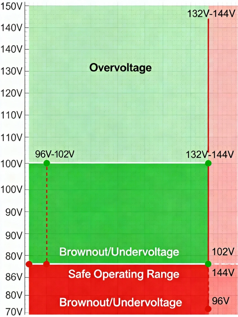
รูปที่ 1: หน้าต่างป้องกันแรงดันไฟฟ้า 80/110 แสดงช่วงการทำงานที่ปลอดภัย (โซนสีเขียว: 96-144V สำหรับระบบปกติ 120V) และโซนอันตรายที่ความเสียหายของอุปกรณ์เกิดขึ้น แรงดันไฟฟ้าต่ำกว่า 96V ทำให้มอเตอร์หยุดทำงานและความเสียหายของคอมเพรสเซอร์ แรงดันไฟฟ้าเกิน 144V เร่งอายุและความล้มเหลวของส่วนประกอบอิเล็กทรอนิกส์ อุปกรณ์ป้องกันแรงดันไฟฟ้าที่อยู่อาศัยส่วนใหญ่ใช้หน้าต่างนี้เป็นจุดเริ่มต้น โดยมีเกณฑ์ที่ปรับได้สำหรับความต้องการอุปกรณ์เฉพาะ.
ขั้นตอนที่ 3: ตรรกะการหน่วงเวลา
นี่คือจุดที่อุปกรณ์ป้องกันแรงดันไฟฟ้าได้รับความซับซ้อน: ฟังก์ชันหน่วงเวลา หากไม่มีการหน่วงเวลา ทุกเหตุการณ์การสับเปลี่ยนของสาธารณูปโภคสั้นๆ หรือแรงดันไฟฟ้าตกชั่วขณะจะตัดวงจรของคุณ—เวลาหยุดทำงานที่ไม่จำเป็น ผู้ใช้หงุดหงิด และหน้าสัมผัสรีเลย์สึกหรอจากการหมุนเวียนอย่างต่อเนื่อง.
การหน่วงเวลาช่วยให้มั่นใจได้ว่าตัวป้องกันจะตัดการเชื่อมต่อเฉพาะในกรณีที่แรงดันไฟฟ้าผิดปกติ ยังคงอยู่ เป็นระยะเวลาที่กำหนด นี่คือสิ่งสำคัญในการหลีกเลี่ยง กับดักการตัดการทำงานที่ไม่จำเป็น: ตั้งค่าความล่าช้าสั้นเกินไป และคุณจะตัดการทำงานจากไฟกระชากชั่วขณะที่ไม่เป็นอันตราย (การสตาร์ทมอเตอร์สั้นๆ, การสับเปลี่ยนของสาธารณูปโภค) ตั้งค่าให้ยาวเกินไป และคุณจะปล่อยให้ความเค้นจากแรงดันไฟฟ้าที่เป็นอันตรายยังคงอยู่.
ช่วงเวลาหน่วงเวลาทั่วไป:
- การหน่วงเวลาการตัดการเชื่อมต่อแรงดันไฟฟ้าต่ำ: 0.5 ถึง 2.0 วินาที (อนุญาตให้แรงดันไฟฟ้าตกสั้นๆ ผ่านไปได้; ตัดการทำงานจากไฟตกอย่างต่อเนื่อง)
- การหน่วงเวลาการตัดการเชื่อมต่อแรงดันไฟฟ้าเกิน: 0.1 ถึง 1.0 วินาที (การตอบสนองที่เร็วกว่าเพราะความเสียหายจากแรงดันไฟฟ้าเกินเกิดขึ้นเร็วกว่า)
- การหน่วงเวลาการเชื่อมต่อใหม่: 30 วินาที ถึง 5 นาที (เพื่อให้มั่นใจว่าแรงดันไฟฟ้าคงที่ก่อนจ่ายไฟใหม่ ซึ่งสำคัญอย่างยิ่งต่อการป้องกันคอมเพรสเซอร์ ป้องกันการรีสตาร์ทแบบช่วงสั้นๆ ที่ทำลายมอเตอร์)
หน่วย AVS สำหรับที่อยู่อาศัยส่วนใหญ่มาพร้อมกับการตั้งค่าจากโรงงานที่มีการหน่วงเวลาที่เหมาะสม (เช่น ตัดการเชื่อมต่อ 0.5 วินาที, เชื่อมต่อใหม่ 3 นาที) และมีการปรับผ่านปุ่มหมุนหรือปุ่มกด การหน่วงเวลาการเชื่อมต่อใหม่ 3 นาทีมีความสำคัญอย่างยิ่งสำหรับตู้เย็นและเครื่องปรับอากาศ ซึ่งจะป้องกันไม่ให้คอมเพรสเซอร์รีสตาร์ททันทีหลังจากไฟฟ้าดับ ซึ่งอาจทำให้คอมเพรสเซอร์เสียหายได้หากแรงดันน้ำยาทำความเย็นยังไม่เท่ากัน.
ขั้นตอนที่ 4: การตัดการเชื่อมต่อและการเชื่อมต่อใหม่โดยอัตโนมัติ
เมื่อหมดเวลาหน่วงและสภาวะแรงดันไฟฟ้ายังคงอยู่ อุปกรณ์ป้องกันจะตัดการเชื่อมต่อโหลด อย่างไร?
หน่วย AVS ที่เชื่อมต่อแบบอนุกรม (อุปกรณ์ป้องกันเครื่องใช้ไฟฟ้า) ใช้รีเลย์ภายในหรือ contactor ที่เปิดวงจรระหว่างแหล่งจ่ายไฟและโหลดทางกายภาพ หน่วยจะอยู่ในแนวเดียวกับแหล่งจ่ายไฟที่เชื่อมต่อกับอินพุต เครื่องใช้ไฟฟ้าของคุณเชื่อมต่อกับเอาต์พุต เมื่อแรงดันไฟฟ้าไม่ดี รีเลย์จะเปิดขึ้น และอุปกรณ์ของคุณจะเห็นแรงดันไฟฟ้าเป็นศูนย์ ปลอดภัย.
รีเลย์ตรวจสอบแรงดันไฟฟ้าแบบ DIN-rail (หน่วยที่ติดตั้งบนแผง) ให้หน้าสัมผัสเอาต์พุต (โดยทั่วไปคือ SPDT: single-pole, double-throw) ที่ส่งสัญญาณไปยังอุปกรณ์ควบคุมภายนอก คุณต่อสายหน้าสัมผัสนี้เพื่อควบคุม shunt trip ของ circuit breaker, คอยล์คอนแทคเตอร์ หรืออินพุตของระบบควบคุม รีเลย์เองไม่ได้นำกระแสโหลด เพียงแค่ส่งสัญญาณทริป.
หลังจากตัดการเชื่อมต่อ อุปกรณ์ป้องกันจะตรวจสอบแรงดันไฟฟ้าของแหล่งจ่ายไฟต่อไป เมื่อแรงดันไฟฟ้ากลับสู่ช่วงที่ยอมรับได้ แล้ว ยังคงมีเสถียรภาพในช่วงเวลาหน่วงการเชื่อมต่อใหม่ อุปกรณ์จะปิดรีเลย์โดยอัตโนมัติ ทำให้จ่ายไฟกลับคืน คุณไม่จำเป็นต้องรีเซ็ตด้วยตนเอง เป็นการกู้คืนโดยอัตโนมัติ.
บางหน่วยมีปุ่ม override ด้วยตนเอง (บังคับให้เชื่อมต่อใหม่, บังคับให้ตัดการเชื่อมต่อ) และไฟ LED แสดงสถานะแรงดันไฟฟ้าปัจจุบัน (ปกติ, แรงดันไฟฟ้าต่ำเกินไป, แรงดันไฟฟ้าสูงเกินไป, ตัดการเชื่อมต่อ) รุ่นที่สูงกว่าเพิ่มคุณสมบัติเช่น การป้องกันไฟกระชาก (MOV protection integrated), การตรวจจับการสูญเสีย neutral (เปิดวงจรหากการเชื่อมต่อ neutral ขาดหายไป) และจอแสดงผลดิจิตอลที่แสดงแรงดันไฟฟ้าแบบเรียลไทม์.
มืออาชีพ-บ#2: การหน่วงเวลาการเชื่อมต่อใหม่มีความสำคัญเช่นเดียวกับเกณฑ์การตัดการเชื่อมต่อ คอมเพรสเซอร์และมอเตอร์ต้องการเวลาเพื่อให้แรงดันน้ำยาทำความเย็นเท่ากันและสภาวะทางความร้อนคงที่ การหน่วงเวลาการเชื่อมต่อใหม่ 3 นาทีจะป้องกันความเสียหายจากการ short-cycling ซึ่งเป็นตัวการสำคัญที่ทำลายคอมเพรสเซอร์ AC และตู้เย็น หากอุปกรณ์ป้องกันแรงดันไฟฟ้าของคุณอนุญาตให้ปรับได้ อย่าลดเวลาหน่วงนี้ต่ำกว่า 2 นาทีสำหรับโหลดมอเตอร์.
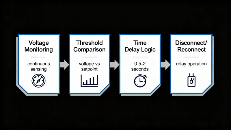
รูปที่ 2: การทำงานสี่ขั้นตอนของอุปกรณ์ป้องกันแรงดันไฟฟ้าเกินและต่ำกว่า อุปกรณ์จะตรวจสอบแรงดันไฟฟ้าอย่างต่อเนื่อง (ขั้นตอนที่ 1) เปรียบเทียบค่าที่วัดได้กับเกณฑ์ที่ตั้งไว้ล่วงหน้า (ขั้นตอนที่ 2) ใช้การหน่วงเวลาเพื่อหลีกเลี่ยงการทริปที่ไม่จำเป็นจาก transient ชั่วครู่ (ขั้นตอนที่ 3) จากนั้นตัดการเชื่อมต่อโหลดระหว่างเหตุการณ์แรงดันไฟฟ้าที่ต่อเนื่องและเชื่อมต่อใหม่โดยอัตโนมัติหลังจากแรงดันไฟฟ้าคงที่ (ขั้นตอนที่ 4) ลำดับนี้ป้องกันความเสียหายของอุปกรณ์ในขณะที่ลดการหยุดชะงักของพลังงานที่ไม่จำเป็น.
สถานการณ์จริงที่อุปกรณ์เหล่านี้ป้องกัน
อุปกรณ์ป้องกันแรงดันไฟฟ้าไม่ใช่ประกันตามทฤษฎี แต่ป้องกันความล้มเหลวของอุปกรณ์ที่เฉพาะเจาะจงและมีเอกสารประกอบ นี่คือสถานการณ์ที่พวกเขาได้รับค่าใช้จ่ายคืนหลายเท่า:
สถานการณ์ที่ 1: Brownout ในฤดูร้อนและความล้มเหลวของคอมเพรสเซอร์ AC
คลื่นความร้อนกลางเดือนกรกฎาคม ทุกบ้านในถนนของคุณกำลังเปิดเครื่องปรับอากาศเต็มกำลัง หม้อแปลงจำหน่ายของ utility ได้รับการจัดอันดับสำหรับ 150 kVA แต่ปัจจุบันส่งมอบ 175 kVA แรงดันไฟฟ้าลดลงเหลือ 105-108V (ต่ำกว่า 12-10%) เป็นเวลา 45 นาทีในช่วงเวลาบ่ายที่พีค พัดลมคอนเดนเซอร์ AC ของคุณทำงานช้า คอมเพรสเซอร์พยายามสตาร์ท ไม่สามารถพัฒนาแรงบิดเต็มที่ ดึงกระแส locked-rotor และ thermal overload ภายในทริป หน่วย cycles พยายามสตาร์ท ร้อนเกินไป ทริป เย็นลง พยายามอีกครั้ง หลังจากสาม cycles ขดลวดคอมเพรสเซอร์สะสมความเครียดจากความร้อนเพียงพอที่ฉนวนเริ่มแตกตัว.
เบรกเกอร์ 15A ของคุณ? ไม่เคยขยับ กระแสไฟสูง แต่ไม่ต่อเนื่องนานพอที่จะทริป.
อุปกรณ์ป้องกันแรงดันไฟฟ้าที่ตั้งไว้ที่ 102V (ต่ำกว่า 15%) โดยมีการหน่วงเวลา 1 วินาที จะตัดการเชื่อมต่อ AC หลังจากแรงดันไฟฟ้าต่ำวินาทีแรก ป้องกันความพยายามในการรีสตาร์ทที่เป็นอันตรายทั้งสามครั้ง เมื่อแรงดันไฟฟ้ากลับสู่ปกติ การหน่วงเวลาการเชื่อมต่อใหม่ 3 นาทีทำให้มั่นใจได้ว่าคอมเพรสเซอร์จะรีสตาร์ทเพียงครั้งเดียว ภายใต้แรงดันไฟฟ้าปกติ โดยไม่มีความเครียดจากความร้อน.
ค่าใช้จ่ายที่หลีกเลี่ยงได้: 24,000-45,000 บาท (การเปลี่ยนคอมเพรสเซอร์และค่าแรง).
สถานการณ์ที่ 2: ฝันร้าย Floating Neutral
การเชื่อมต่อ neutral ที่ผุกร่อนที่ weatherhead (ที่ service drop ของคุณเชื่อมต่อกับฐานมิเตอร์ของบ้าน) เปิดออกจนหมด คุณมี split-phase 120/240V service สอง hot leg 120V ที่ 180° out of phase โดยมี neutral return เมื่อ neutral เปิดออก สอง leg จะกลายเป็นวงจรอนุกรมผ่านโหลดของบ้านคุณ หาก leg หนึ่งมีโหลด 1,500W (ไฟ LED, ทีวี, คอมพิวเตอร์) และอีก leg หนึ่งมี 3,000W (ตู้เย็น, ไมโครเวฟ, AC) แรงดันไฟฟ้าจะแบ่งไม่เท่ากัน.
การวัดจริงจากกรณีที่มีเอกสารประกอบ: 165V บน leg ที่มีโหลดน้อย, 75V บน leg ที่มีโหลดมาก 240V leg-to-leg ยังคงปกติ ดังนั้นเครื่องอบผ้าและเตาอบ 240V ของคุณทำงานได้ดี บดบังปัญหา.
Leg 165V: หลอดไฟ LED ทุกดวงดับ (ไฟกระชาก แล้วความมืด) แหล่งจ่ายไฟของทีวีล้มเหลวด้วยเสียงดังและกลิ่นไหม้ เมนบอร์ดของคอมพิวเตอร์ไหม้ เทอร์โมสตัทอัจฉริยะของคุณละลาย ความเสียหายทั้งหมด: 1,200-3,500 บาท.
Leg 75V: คอมเพรสเซอร์ตู้เย็นฮัม แต่ไม่สตาร์ท ไมโครเวฟทำงานด้วยกำลังไฟครึ่งเดียว คอนเดนเซอร์ AC ไม่สตาร์ท ไม่มีความเสียหายในทันที แต่ถ้าปล่อยทิ้งไว้หลายชั่วโมง คอมเพรสเซอร์ตู้เย็นจะไหม้จากการพยายาม stall ซ้ำๆ.
อุปกรณ์ป้องกันแรงดันไฟฟ้าที่มีการตรวจจับ neutral-loss (พบได้ทั่วไปในหน่วย AVS คุณภาพ) จะตรวจจับสภาวะนี้ทันที ไม่ว่าจะโดยการตรวจจับว่า leg หนึ่งสูงและอีก leg หนึ่งต่ำ หรือโดยการตรวจสอบความต่อเนื่องของ neutral โดยตรง อุปกรณ์ป้องกันจะเปิดภายใน 0.5-1 วินาที แยกอุปกรณ์ทั้งหมดก่อนที่จะเกิดความเสียหาย เมื่อช่างไฟฟ้าแก้ไขการเชื่อมต่อ neutral อุปกรณ์ป้องกันจะเชื่อมต่อใหม่โดยอัตโนมัติหลังจากแรงดันไฟฟ้าคงที่.
ค่าใช้จ่ายที่หลีกเลี่ยงได้: 1,200-5,000+ บาท (การเปลี่ยนเครื่องใช้ไฟฟ้าและอุปกรณ์อิเล็กทรอนิกส์หลายรายการ).

รูปที่ 3: สถานการณ์ Floating Neutral แสดงให้เห็นถึงแรงดันไฟฟ้าเกินและแรงดันไฟฟ้าต่ำพร้อมกันเมื่อตัวนำ neutral เปิดใน split-phase 120/240V service Leg ที่มีโหลดน้อยจะเห็น 165V (สีแดง) ทำให้อุปกรณ์อิเล็กทรอนิกส์เสียหายทันที ในขณะที่ leg ที่มีโหลดมากจะลดลงเหลือ 75V (สีส้ม) ทำให้มอเตอร์ stall แรงดันไฟฟ้าระหว่างสายยังคงปกติที่ 240V บดบังปัญหาจนกว่าอุปกรณ์จะล้มเหลว อุปกรณ์ป้องกันแรงดันไฟฟ้าที่มีการตรวจจับ neutral-loss ป้องกันโหมดความล้มเหลวร้ายแรงนี้.
สถานการณ์ที่ 3: ความล้มเหลวของ Utility Voltage Regulator
Automatic voltage regulator (AVR) ของ utility ในพื้นที่ของคุณบน distribution feeder ล้มเหลวในตำแหน่ง “boost” ซึ่งมีวัตถุประสงค์เพื่อชดเชยแรงดันไฟฟ้าตกที่ปลาย feeder ในชนบทที่ยาว แต่คุณอยู่ใกล้กับ substation ดังนั้นคุณไม่จำเป็นต้อง boost บ้านของคุณจึงเห็น 126-130V อย่างต่อเนื่อง (สูงกว่า 5-8%) เป็นเวลาหกชั่วโมงจนกว่า utility จะตอบสนองต่อข้อร้องเรียนของลูกค้า.
ไม่มีความล้มเหลวร้ายแรงในทันที แต่ทุกชั่วโมงที่ 128V กำลังเร่งอายุใน:
- ตัวเก็บประจุ LED driver (ออกแบบมาสำหรับ 120V ± 10%)
- บอร์ดควบคุมตู้เย็น
- แหล่งจ่ายไฟทีวี
- แหล่งจ่ายไฟคอมพิวเตอร์
- เครื่องชาร์จแบตเตอรี่และ power adapter
อุปกรณ์ที่ได้รับการจัดอันดับสำหรับ “120V, 60Hz” โดยทั่วไปมีช่วงที่ยอมรับได้ 108-132V ที่ 128-130V คุณอยู่ที่ขอบบนสุด หรือเกินกว่านั้น ส่วนประกอบทำงานร้อนขึ้น ตัวเก็บประจุ electrolytic สูญเสียอายุการใช้งานแบบทวีคูณ (ทุกๆ อุณหภูมิที่เพิ่มขึ้น 10°C จะลดอายุการใช้งานลง 50%) เหตุการณ์ overvoltage หกชั่วโมงอาจไม่ฆ่าอะไรในวันนี้ แต่เพิ่งทำให้อุปกรณ์อิเล็กทรอนิกส์ทุกชิ้นในบ้านของคุณมีอายุมากขึ้นเป็นสัปดาห์หรือเดือน.
อุปกรณ์ป้องกันแรงดันไฟฟ้าที่ตั้งไว้ที่ 132V (110%) โดยมีการหน่วงเวลา 0.5 วินาที จะตัดการเชื่อมต่ออุปกรณ์ของคุณภายในวินาทีแรกของ overvoltage ที่ต่อเนื่อง เมื่อแรงดันไฟฟ้าของ utility กลับสู่ปกติ อุปกรณ์จะเชื่อมต่อใหม่ ไม่มีการ aging ไม่มีความเครียด ไม่มีอายุการใช้งานที่สั้นลง.
ค่าใช้จ่ายที่หลีกเลี่ยงได้: เป็นไปไม่ได้ที่จะระบุปริมาณได้อย่างแม่นยำ แต่การหลีกเลี่ยงการ aging ที่เร่งขึ้นจะเพิ่มอายุการใช้งานของอุปกรณ์อิเล็กทรอนิกส์ทุกชิ้นในบ้านของคุณเป็นเดือนถึงปี อย่างระมัดระวัง: 500-2,000 บาท ในอายุการใช้งานอุปกรณ์ที่ยาวนานขึ้นในช่วง 5-10 ปี.
มืออาชีพ-บ#3: อุปกรณ์ป้องกันแรงดันไฟฟ้ามีความสำคัญอย่างยิ่งสำหรับบ้านที่มีโหลดมอเตอร์ราคาแพง (AC ส่วนกลาง, ปั๊มสระว่ายน้ำ, ปั๊มน้ำบาดาล) และอุปกรณ์อิเล็กทรอนิกส์ที่ละเอียดอ่อน (โฮมเธียเตอร์, คอมพิวเตอร์, ระบบ smart home) หากคุณอาศัยอยู่ในพื้นที่ที่มีโครงสร้างพื้นฐานของ utility ที่เก่า, พายุบ่อยครั้ง หรือคุณภาพไฟฟ้าที่ไม่น่าเชื่อถือ การลงทุน 60-150 บาทในการป้องกันแรงดันไฟฟ้าจะจ่ายคืนเองหลังจากป้องกันความล้มเหลวของอุปกรณ์เพียงครั้งเดียว.
ประเภทของอุปกรณ์ป้องกันแรงดันไฟฟ้า: AVS vs DIN-Rail Relays
อุปกรณ์ป้องกันแรงดันไฟฟ้าเกินและต่ำกว่ามีสองประเภทหลัก แต่ละประเภทได้รับการออกแบบมาสำหรับสถานการณ์การติดตั้งและความต้องการของผู้ใช้ที่แตกต่างกัน:
Automatic Voltage Switchers (AVS) – การป้องกันระดับเครื่องใช้ไฟฟ้า
หน่วย AVS เป็นอุปกรณ์ที่เชื่อมต่อแบบอนุกรมซึ่งออกแบบมาสำหรับการป้องกันแบบ plug-and-play ของเครื่องใช้ไฟฟ้าหรือวงจรเฉพาะ พวกเขาดูเหมือนกล่องรวมสายขนาดเล็กที่มีสายไฟอินพุตและเต้ารับเอาต์พุต (หรือขั้วต่อแบบ hardwire).
วิธีการติดตั้ง: AVS เชื่อมต่อระหว่าง circuit breaker ของคุณและโหลดที่ได้รับการป้องกัน สำหรับเครื่องปรับอากาศหน้าต่าง คุณจะเสียบ AVS เข้ากับเต้ารับที่ผนัง จากนั้นเสียบ AC เข้ากับ AVS สำหรับ AC ส่วนกลางหรือเครื่องใช้ไฟฟ้าแบบ hardwired ช่างไฟฟ้าจะติดตั้ง AVS แบบ inline ในกล่องรวมสายใกล้กับอุปกรณ์.
ข้อกำหนดทั่วไป:
- พิกัดแรงดันไฟฟ้า: 120V หรือ 240V single-phase
- พิกัดกระแสไฟฟ้า: 15A ถึง 100A (ขึ้นอยู่กับรุ่น)
- เกณฑ์แรงดันไฟฟ้าต่ำเกินไป: 85-95V (บนระบบ 120V) โดยทั่วไปจะคงที่หรือปรับได้ 2 ตำแหน่ง
- เกณฑ์แรงดันไฟฟ้าสูงเกินไป: 135-145V (บนระบบ 120V) โดยทั่วไปจะคงที่
- การหน่วงเวลาการเชื่อมต่อใหม่: 30 วินาที ถึง 5 นาที ปรับได้ผ่านปุ่มหมุนหรือปุ่มกด
- คุณสมบัติเพิ่มเติม: การป้องกันไฟกระชาก (MOV protection integrated), การตรวจจับ neutral-loss, ไฟ LED แสดงสถานะ, ปุ่ม override ด้วยตนเอง
เหมือนกันโปรแกรม:
- การป้องกันเครื่องปรับอากาศส่วนกลางและฮีทปั๊ม
- การป้องกันตู้เย็นและตู้แช่แข็ง
- การป้องกันปั๊มน้ำบาดาลและปั๊มสระว่ายน้ำ
- การป้องกันทั้งวงจร (ติดตั้งที่ sub-panel เพื่อป้องกันพื้นที่ทั้งหมด)
- การป้องกันทางเข้าไฟ RV และ mobile home
ข้อดี: ติดตั้งง่าย (เป็นมิตรกับ DIY สำหรับรุ่น plug-in), โซลูชัน all-in-one, การควบคุมและตัวบ่งชี้ที่ใช้งานง่าย โดยทั่วไปรวมถึงการป้องกันไฟกระชากและการตรวจจับ neutral-loss.
ข้อเสีย: แต่ละหน่วยป้องกันหนึ่งโหลดหรือวงจร (ต้องการหลายหน่วยสำหรับการป้องกันทั้งบ้าน), การปรับที่จำกัดเมื่อเทียบกับรีเลย์ DIN-rail, การเชื่อมต่อแบบอนุกรมหมายความว่าหน่วยต้องนำกระแสโหลดเต็มที่ (ต้องมีพิกัดกระแสไฟฟ้าที่เหมาะสม).
ช่วงราคา: 60-250 บาท ขึ้นอยู่กับพิกัดกระแสไฟฟ้าและคุณสมบัติ AVS 30A ทั่วไปสำหรับ AC ส่วนกลางมีราคา 80-120 บาท.
DIN-Rail Voltage Monitoring Relays – การรวมแผง
รีเลย์ DIN-rail เป็นโมดูลขนาดกะทัดรัดที่ออกแบบมาเพื่อติดตั้งบน DIN rail มาตรฐานภายในแผงไฟฟ้าหรือตู้ควบคุม พวกเขาไม่ได้นำกระแสโหลด แต่ให้หน้าสัมผัสเอาต์พุตที่ส่งสัญญาณไปยังอุปกรณ์ควบคุมภายนอก (คอนแทคเตอร์, breaker shunt trips).
[รูปภาพของรีเลย์ตรวจสอบแรงดันไฟฟ้าแบบ DIN-rail]
วิธีการติดตั้ง: รีเลย์ติดตั้งบน ราง DIN ใน เพราะไฟฟ้าลัดวงจพาเนล. ราง DIN ของคุณ ขั้วต่อตรวจจับเชื่อมต่อกับแรงดันไฟฟ้าที่ตรวจสอบ (สายถึงนิวทรัล หรือ สายถึงสาย) หน้าสัมผัสเอาต์พุตต่อสายเข้ากับวงจรควบคุม—ตัวอย่างเช่น ต่อสายอนุกรมกับคอยล์คอนแทคเตอร์ เพื่อให้เมื่อแรงดันไฟฟ้าผิดปกติ หน้าสัมผัสจะเปิดออก คอนแทคเตอร์จะหลุด และโหลดจะถูกตัดการเชื่อมต่อ.
ข้อกำหนดทั่วไป:
- ช่วงการตรวจจับแรงดันไฟฟ้า: 24-600VAC, โดยทั่วไปสามารถเลือกได้ในสนาม
- การปรับค่าการทำงาน: 10-100% ของช่วงที่เลือก, ปรับได้อย่างต่อเนื่อง หรือ เลือกได้ด้วย DIP-switch
- Hysteresis: 5-50%, ปรับได้ (ป้องกันการสั่น)
- Time delay: 0.1-30 วินาที, ปรับได้
- พิกัดหน้าสัมผัสเอาต์พุต: 5A ที่ 250VAC (หน้าสัมผัสรีเลย์ SPDT)
- การติดตั้ง: ราง DIN 35 มม. (ความกว้าง 17.5 มม. หรือ 22.5 มม.)
เหมือนกันโปรแกรม:
- การป้องกันแผงจ่ายไฟ (หลายวงจรได้รับการป้องกันผ่านการควบคุมคอนแทคเตอร์)
- การติดตั้งเชิงพาณิชย์ขนาดเล็กและอุตสาหกรรมขนาดเล็ก
- ระบบควบคุมปั๊ม, ระบบควบคุม HVAC, ระบบชลประทาน
- อุปกรณ์ที่มีระบบควบคุมแบบคอนแทคเตอร์อยู่แล้ว (รีเลย์รวมเข้ากับตรรกะการควบคุมที่มีอยู่)
ข้อดี: การติดตั้งที่ยืดหยุ่นในแผงไฟฟ้า, เกณฑ์และเวลาหน่วงที่ปรับได้สูง, หน้าสัมผัสเอาต์พุตรวมเข้ากับระบบควบคุมที่มีอยู่, สามารถป้องกันหลายวงจรด้วยรีเลย์ตัวเดียว (หากใช้คอนแทคเตอร์ร่วมกัน), รูปลักษณ์ที่เป็นมืออาชีพในการติดตั้งแผง.
ข้อเสีย: ต้องมีการรวมเข้ากับแผงโดยช่างไฟฟ้าที่มีใบอนุญาต, ไม่นำกระแสโหลด (ต้องการคอนแทคเตอร์ภายนอกหรือ Shunt Trip ของเบรกเกอร์), การกำหนดค่าซับซ้อนกว่าหน่วย AVS, โดยทั่วไปไม่มีการป้องกันไฟกระชากหรือการตรวจจับการสูญเสียนิวทรัล (สิ่งเหล่านั้นต้องใช้อุปกรณ์แยกต่างหาก).
ช่วงราคา: ฿80-฿300 ขึ้นอยู่กับคุณสมบัติ, ยี่ห้อ และช่วงแรงดันไฟฟ้า รีเลย์ตรวจสอบแรงดันไฟฟ้าเฟสเดียวทั่วไปมีราคา ฿120-฿180.
คุณควรเลือกประเภทใด
เลือกหน่วย AVS หาก:
- คุณต้องการปกป้องเครื่องใช้ไฟฟ้าเฉพาะ (AC, ตู้เย็น, ตู้แช่แข็ง, ปั๊มน้ำ)
- คุณต้องการการติดตั้งแบบ Plug-and-Play หรือแบบ Inline ที่เรียบง่าย
- คุณต้องการการป้องกันแบบ All-in-One (แรงดันไฟฟ้า + ไฟกระชาก + การสูญเสียนิวทรัล)
- คุณเป็นเจ้าของบ้านที่กำลังมองหาการป้องกันที่สามารถติดตั้งได้ด้วยตนเอง
เลือกรีเลย์ DIN-rail หาก:
- คุณกำลังออกแบบแผงไฟฟ้าใหม่หรืออัพเกรดแผงไฟฟ้าที่มีอยู่
- คุณต้องการการป้องกันแบบรวมศูนย์สำหรับหลายวงจร
- คุณมีระบบควบคุมแบบคอนแทคเตอร์อยู่แล้วที่รีเลย์สามารถรวมเข้าด้วยกันได้
- คุณต้องการเกณฑ์และเวลาหน่วงที่ปรับได้สูงสำหรับอุปกรณ์เฉพาะทาง
- คุณกำลังทำงานกับแอปพลิเคชันเชิงพาณิชย์ขนาดเล็กหรืออุตสาหกรรม
สำหรับผู้ใช้ที่อยู่อาศัยส่วนใหญ่ที่ต้องการปกป้องเครื่องใช้ไฟฟ้าที่มีมูลค่าสูง หน่วย AVS เป็นตัวเลือกที่ใช้งานได้จริง สำหรับช่างไฟฟ้าและผู้สร้างแผงที่ทำงานเกี่ยวกับการก่อสร้างใหม่หรือการอัพเกรดแผง รีเลย์ DIN-rail ให้ความยืดหยุ่นและการรวมระบบที่เป็นมืออาชีพมากกว่า.
การติดตั้งและการตั้งค่า: หน้าต่าง 80/110
การติดตั้งและกำหนดค่าอุปกรณ์ป้องกันแรงดันไฟฟ้าเกินและแรงดันไฟฟ้าต่ำอย่างถูกต้องช่วยให้มั่นใจได้ถึงการป้องกันโดยไม่มีการตัดวงจรที่ไม่จำเป็น นี่คือวิธีการทำอย่างถูกต้อง:
แนวทางการติดตั้ง
สำหรับหน่วย AVS (การป้องกันเครื่องใช้ไฟฟ้า):
- ตรวจสอบพิกัดกระแสไฟฟ้า: AVS ต้องมีพิกัดอย่างน้อยเท่ากับกระแสไฟฟ้าเต็มพิกัดของอุปกรณ์ที่ได้รับการป้องกัน สำหรับ AC แบบหน้าต่างขนาด 13,000 BTU ที่ดึงกระแส 11A ให้ใช้ AVS ขนาด 15A หรือ 20A สำหรับ AC ส่วนกลางที่มีเบรกเกอร์ 30A ให้ใช้ AVS ขนาด 30A หรือ 40A ห้ามลดขนาด—หน้าสัมผัสรีเลย์จะร้อนเกินไปและล้มเหลว.
- การเชื่อมต่อแบบอนุกรมที่มีขั้วที่ถูกต้อง: หน่วย AVS เชื่อมต่อแบบ Inline ระหว่างแหล่งจ่ายและโหลด สิ่งสำคัญ: เชื่อมต่อสาย (ร้อน) กับขั้วต่อ LINE อินพุตของ AVS และขั้วต่อ LOAD เอาต์พุตของ AVS กับการเชื่อมต่อสายของอุปกรณ์ ห้ามสลับสายและโหลด—สิ่งนี้จะทำให้โหลดได้รับพลังงานแม้ในขณะที่ AVS ตัดการเชื่อมต่อ ซึ่งก่อให้เกิดอันตรายจากไฟฟ้าช็อต สำหรับโหลด 240V ตัวนำร้อนทั้งสองจะผ่าน AVS โดยตรง สายนิวทรัลและสายดินจะผ่านโดยตรง (ไม่สวิตช์).
- ตำแหน่งการติดตั้ง: ติดตั้ง AVS ในตำแหน่งที่มีการระบายอากาศซึ่งคุณสามารถเห็นไฟ LED แสดงสถานะและเข้าถึงส่วนควบคุมการปรับได้ สำหรับอุปกรณ์กลางแจ้ง (คอนเดนเซอร์ AC) ให้ใช้กล่องหุ้มที่ทนทานต่อสภาพอากาศ (NEMA 3R ขั้นต่ำ) เพื่อบรรจุ AVS อย่าวางไว้ในผนังหรือกล่องรวมสายที่ไม่สามารถเข้าถึงได้—คุณจะต้องตรวจสอบไฟ LED ระหว่างการแก้ไขปัญหา.
- การเดินสายที่ปลอดภัย: ใช้ขั้วต่อสายไฟที่เหมาะสม (Wire Nuts สำหรับสายตีเกลียวกับสายแข็ง, Crimp Terminals สำหรับ Terminal Blocks) ขันสกรูขั้วต่อให้แน่นตามข้อกำหนดแรงบิดของผู้ผลิต (โดยทั่วไปคือ 10-15 in-lb สำหรับสายขนาด 10-14 AWG) การเชื่อมต่อที่หลวมจะสร้างความต้านทาน ความร้อน และแรงดันไฟฟ้าตก—ซึ่งเป็นสิ่งที่คุณกำลังพยายามป้องกัน.
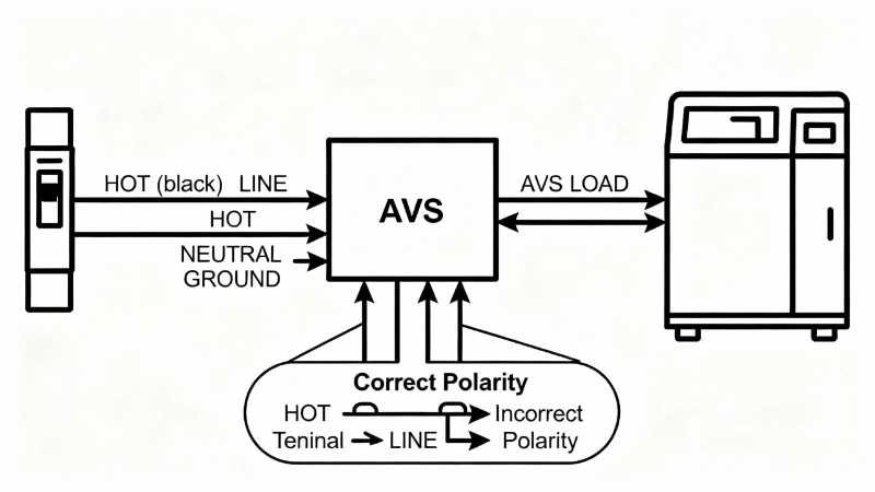
รูปที่ 4: การติดตั้งหน่วย AVS ที่เหมาะสมซึ่งแสดงการเชื่อมต่อแบบอนุกรมระหว่าง Circuit Breaker และโหลดที่ได้รับการป้องกัน ตัวนำร้อน (สีดำ) เชื่อมต่อจากเบรกเกอร์ไปยังขั้วต่อ LINE ของ AVS จากนั้นจากขั้วต่อ LOAD ของ AVS ไปยังอุปกรณ์ สายนิวทรัลและสายดินจะผ่านโดยไม่สวิตช์ ข้อควรระวังด้านความปลอดภัยที่สำคัญ: ห้ามสลับการเชื่อมต่อ LINE และ LOAD—สิ่งนี้จะทำให้โหลดได้รับพลังงานแม้ในขณะที่ AVS ตัดการเชื่อมต่อ ซึ่งก่อให้เกิดอันตรายจากไฟฟ้าช็อตและทำให้การป้องกันล้มเหลว.
สำหรับรีเลย์ DIN-rail (การรวมเข้ากับแผง):
- การติดตั้งบนราง DIN: สแน็ฟรีเลย์เข้ากับราง DIN 35 มม. ในแผงไฟฟ้า วางตำแหน่งในที่ที่คุณสามารถเห็นไฟ LED แสดงสถานะและเข้าถึงส่วนควบคุมการปรับได้โดยไม่ต้องเอื้อมมือข้าม Busbar ที่มีไฟฟ้า.
- การเชื่อมต่อตรวจจับแรงดันไฟฟ้า: เชื่อมต่อขั้วต่อตรวจจับแรงดันไฟฟ้าของรีเลย์ข้ามแรงดันไฟฟ้าที่ตรวจสอบ สำหรับการตรวจสอบสายถึงนิวทรัล (พบบ่อยที่สุดในการใช้งาน 120V ในที่อยู่อาศัย) ให้เชื่อมต่อ L กับ Busbar ร้อน และ N กับ Neutral Bar สำหรับการตรวจสอบสายถึงสาย (อุปกรณ์ 240V) ให้เชื่อมต่อ L1 และ L2 กับสายร้อนทั้งสอง ใช้สายไฟขนาดที่เหมาะสม (โดยทั่วไปคือ 14 หรือ 12 AWG) และตรวจสอบให้แน่ใจว่าการเชื่อมต่อแน่นหนา.
- การเดินสายหน้าสัมผัสเอาต์พุต: หน้าสัมผัสเอาต์พุต SPDT ของรีเลย์ต่อสายเข้ากับวงจรควบคุม การกำหนดค่าทั่วไป:
- อนุกรมกับคอยล์คอนแทคเตอร์: หน้าสัมผัส NO (Normally Open) ของรีเลย์ต่ออนุกรมกับคอยล์คอนแทคเตอร์ เมื่อแรงดันไฟฟ้าเป็นปกติ หน้าสัมผัสจะปิด ทำให้คอนแทคเตอร์ได้รับพลังงาน เมื่อแรงดันไฟฟ้าไม่ดี หน้าสัมผัสจะเปิดออก ทำให้คอนแทคเตอร์หลุดและตัดการเชื่อมต่อโหลด.
- Breaker Shunt Trip: หน้าสัมผัส NO ของรีเลย์ต่อสายกับ Shunt Trip Coil ของเบรกเกอร์ เมื่อแรงดันไฟฟ้าไม่ดี หน้าสัมผัสจะปิด ทำให้ Shunt Trip ได้รับพลังงาน และเปิดเบรกเกอร์.
- การติดฉลาก: ติดป้ายกำกับรีเลย์ให้ชัดเจน (“Voltage Monitor – AC Compressor” หรือ “UV/OV Relay – Circuit 12”) ช่างไฟฟ้าในอนาคตจะขอบคุณคุณ.
การตั้งค่า: หน้าต่าง 80/110
หน้าต่าง 80/110 เป็นกฎทั่วไปในอุตสาหกรรมสำหรับการป้องกันแรงดันไฟฟ้าในที่อยู่อาศัยและเชิงพาณิชย์ขนาดเล็ก:
- เกณฑ์แรงดันไฟฟ้าต่ำ: 80-85% ของแรงดันไฟฟ้าปกติ
- ระบบ 120V: 96-102V
- ระบบ 208V: 166-177V
- ระบบ 240V: 192-204V
ช่วงนี้ช่วยให้แรงดันไฟฟ้าตกตามปกติ (ความต้านทานของสายไฟ การควบคุมของ Utility) โดยไม่ตัดวงจร ในขณะที่จับ Brownout ที่ทำให้อุปกรณ์เสียหาย.
- เกณฑ์แรงดันไฟฟ้าเกิน: 110-120% ของแรงดันไฟฟ้าปกติ
- ระบบ 120V: 132-144V
- ระบบ 208V: 229-250V
- ระบบ 240V: 264-288V
ช่วงนี้จะจับแรงดันไฟฟ้าเกินที่ต่อเนื่อง (ความล้มเหลวของ Regulator, Floating Neutral) ในขณะที่ทนต่อแรงดันไฟฟ้าที่เพิ่มขึ้นในช่วงสั้นๆ จากการสลับ Capacitor หรือการปิดมอเตอร์.
การตั้งค่าหน่วงเวลาการตัดการเชื่อมต่อ:
- แรงดันไฟฟ้าต่ำเกินไป: 0.5-2.0 วินาที เริ่มต้นด้วย 1.0 วินาที ปรับให้กระชับเป็น 0.5 วินาที หากคุณมีอุปกรณ์อิเล็กทรอนิกส์ที่ไวต่อแรงดันไฟฟ้า ขยายเป็น 2.0 วินาที หากคุณพบปัญหาการตัดวงจรที่ไม่พึงประสงค์จากการสลับแหล่งจ่ายไฟของการไฟฟ้าในช่วงเวลาสั้นๆ.
- แรงดันไฟฟ้าสูงเกินไป: 0.3-1.0 วินาที เริ่มต้นด้วย 0.5 วินาที ความเสียหายจากแรงดันไฟฟ้าเกินเกิดขึ้นเร็วกว่าความเสียหายจากความร้อนเนื่องจากแรงดันไฟฟ้าต่ำเกินไป ดังนั้นให้ใช้การหน่วงเวลาที่สั้นกว่า.
การตั้งค่าหน่วงเวลาการเชื่อมต่อใหม่:
- โหลดมอเตอร์ (AC, ตู้เย็น, ปั๊ม): 3-5 นาที นี่คือสิ่งที่ไม่สามารถต่อรองได้เพื่อการป้องกันคอมเพรสเซอร์ การรีสตาร์ทวงจรสั้นๆ จะทำลายคอมเพรสเซอร์.
- โหลดที่ไม่ใช่มอเตอร์ (อุปกรณ์อิเล็กทรอนิกส์, ไฟส่องสว่าง): 30 วินาที ถึง 2 นาที เพื่อให้แน่ใจว่าแรงดันไฟฟ้าคงที่อย่างแท้จริงและไม่แกว่ง.
มืออาชีพ-บ#4: เมื่อตั้งค่าเกณฑ์ ให้วัดแรงดันไฟฟ้าที่จ่ายจริงของคุณก่อน หากวงจร “120V” ของคุณทำงานที่ 118V อย่างสม่ำเสมอ (การควบคุมของการไฟฟ้าหรือสายบริการที่ยาว) ให้ตั้งค่าเกณฑ์แรงดันไฟฟ้าต่ำเกินไปที่ 95V (80% ของ 118V) แทนที่จะเป็น 96V (80% ของ 120V) ตั้งค่าของคุณตามความเป็นจริง ไม่ใช่แรงดันไฟฟ้าที่ระบุ ใช้มัลติมิเตอร์ True-RMS และวัดที่จุดเชื่อมต่อของอุปกรณ์ที่ได้รับการป้องกันในช่วงเวลาที่มีโหลดสูงสุด.
เลเยอร์ที่ขาดหายไปในแผนการป้องกันของคุณ
กลับไปที่สถานการณ์เริ่มต้นนั้น: การเปลี่ยนตู้เย็นราคา 3,200 บาท เนื่องจากไฟตกที่ไม่เคยตัดวงจรของคุณ อุปกรณ์ป้องกันแรงดันไฟฟ้า 60-80 บาท จะตัดการเชื่อมต่อคอมเพรสเซอร์ภายในหนึ่งวินาทีหลังจากแรงดันไฟฟ้าต่ำ ป้องกันความเสียหายทั้งหมด นั่นคือผลตอบแทนจากการลงทุน 40:1 จากการป้องกันความล้มเหลวเพียงครั้งเดียว.
เซอร์กิตเบรกเกอร์ อุปกรณ์ GFCI และอุปกรณ์ป้องกันไฟกระชากเป็นสิ่งจำเป็น แต่ยังไม่สมบูรณ์ พวกเขาปล่อยให้ **电压盲区**: ไม่มีการป้องกันเหตุการณ์แรงดันไฟฟ้าที่ต่อเนื่อง (ไฟตก, แรงดันไฟฟ้าเกิน, นิวทรัลลอย) ที่ทำให้อุปกรณ์เสียหายโดยไม่สร้างกระแสไฟเกินที่จำเป็นในการตัดเบรกเกอร์ อุปกรณ์ป้องกันแรงดันไฟฟ้าเกินและต่ำกว่าจะเติมเต็มช่องว่างนั้น ทำหน้าที่เป็นระบบเตือนภัยล่วงหน้าที่ตรวจจับแรงดันไฟฟ้าที่ผิดปกติ ก่อน มันก่อให้เกิดผลกระทบรองที่เป็นอันตราย.
การคำนวณนั้นง่าย การรบกวนของแรงดันไฟฟ้าเกิดขึ้น 10-40 ครั้งต่อปี หากเหตุการณ์เหล่านั้นเพียง 10% จะทำให้อุปกรณ์ที่ไม่ได้รับการป้องกันเสียหาย คุณกำลังเผชิญกับความล้มเหลวที่อาจเกิดขึ้น 1-4 ครั้งต่อปี ปกป้องโหลดมอเตอร์ที่มีราคาแพงที่สุดสามรายการของคุณ (AC ส่วนกลางที่ 3,500 บาท ตู้เย็นที่ 2,800 บาท ปั๊มน้ำบาดาล/สระว่ายน้ำที่ 1,200 บาท) ด้วยอุปกรณ์ป้องกันแรงดันไฟฟ้า (รวม 240 บาท สำหรับหน่วย AVS 30A สามหน่วย) และคุณได้พิสูจน์ความคุ้มค่าของการลงทุนหลังจากป้องกันความล้มเหลวของคอมเพรสเซอร์เพียงครั้งเดียว ความล้มเหลวที่ป้องกันได้หลังจากนั้นคือการประหยัดอย่างแท้จริง.
สำหรับบ้านที่มีโครงสร้างพื้นฐานของการไฟฟ้าที่เก่าแก่ พายุบ่อยครั้ง หรือประวัติความล้มเหลวของอุปกรณ์ที่เกี่ยวข้องกับแรงดันไฟฟ้า การป้องกันแรงดันไฟฟ้าไม่ใช่ทางเลือก แต่เป็นเลเยอร์ที่ขาดหายไปในแผนการป้องกันของคุณ เซอร์กิตเบรกเกอร์ของคุณป้องกันกระแสไฟมากเกินไป อุปกรณ์ป้องกันไฟกระชากของคุณจับการกระชากในช่วงเวลาสั้นๆ อุปกรณ์ป้องกันแรงดันไฟฟ้าจัดการทุกสิ่งทุกอย่าง: แรงดันไฟฟ้าต่ำเกินไปที่ต่อเนื่องซึ่งทำให้คอมเพรสเซอร์เสียหาย แรงดันไฟฟ้าเกินที่ยืดเยื้อซึ่งทำให้อุปกรณ์อิเล็กทรอนิกส์เสื่อมสภาพ และฝันร้ายจากนิวทรัลลอยที่ฆ่าเครื่องใช้ไฟฟ้าของคุณครึ่งหนึ่งในไม่กี่นาที.
พร้อมที่จะปิดจุดบอดของแรงดันไฟฟ้าแล้วหรือยัง? เริ่มต้นด้วยโหลดมอเตอร์ที่มีราคาแพงที่สุดของคุณ AC ส่วนกลาง ตู้เย็น หรือปั๊มน้ำบาดาล ติดตั้งหน่วย AVS ที่มีพิกัดที่เหมาะสม (จับคู่พิกัดกระแสไฟกับเบรกเกอร์ของคุณ) ตั้งค่าเกณฑ์โดยใช้หน้าต่าง 80/110 กำหนดค่าการหน่วงเวลาการเชื่อมต่อใหม่ 3 นาทีสำหรับการป้องกันคอมเพรสเซอร์ และตรวจสอบการติดตั้งด้วยการทดสอบแรงดันไฟฟ้าระหว่างการทำงานปกติ เครื่องใช้ไฟฟ้าที่ได้รับการป้องกันหนึ่งเครื่องคือความล้มเหลวร้ายแรงที่รอการเกิดขึ้นน้อยลงหนึ่งเครื่อง.
มาตรฐา&แหล่งข่าวของลองโยง
- IEC 60364-4-44:2024 (การติดตั้งทางไฟฟ้าแรงดันต่ำ – การป้องกันการรบกวนของแรงดันไฟฟ้า)
- IEC 60255-1:2022 (รีเลย์วัดและอุปกรณ์ป้องกัน – ข้อกำหนดทั่วไป)
- IEEE C37.2-2022 (หมายเลขฟังก์ชันอุปกรณ์ระบบไฟฟ้า)
- ข้อมูลจำเพาะของผู้ผลิต: Sollatek AVS series, Omron K8AK-VS, เอกสารอุตสาหกรรม
- กรณีศึกษาในโลกแห่งความเป็นจริง: การวัดแรงดันไฟฟ้านิวทรัลลอย, การวิเคราะห์ความล้มเหลวของคอมเพรสเซอร์
时效性声明
ข้อมูลจำเพาะของผลิตภัณฑ์ มาตรฐาน และข้อมูลทางเทคนิคทั้งหมดถูกต้อง ณ เดือนพฤศจิกายน 2025.
