
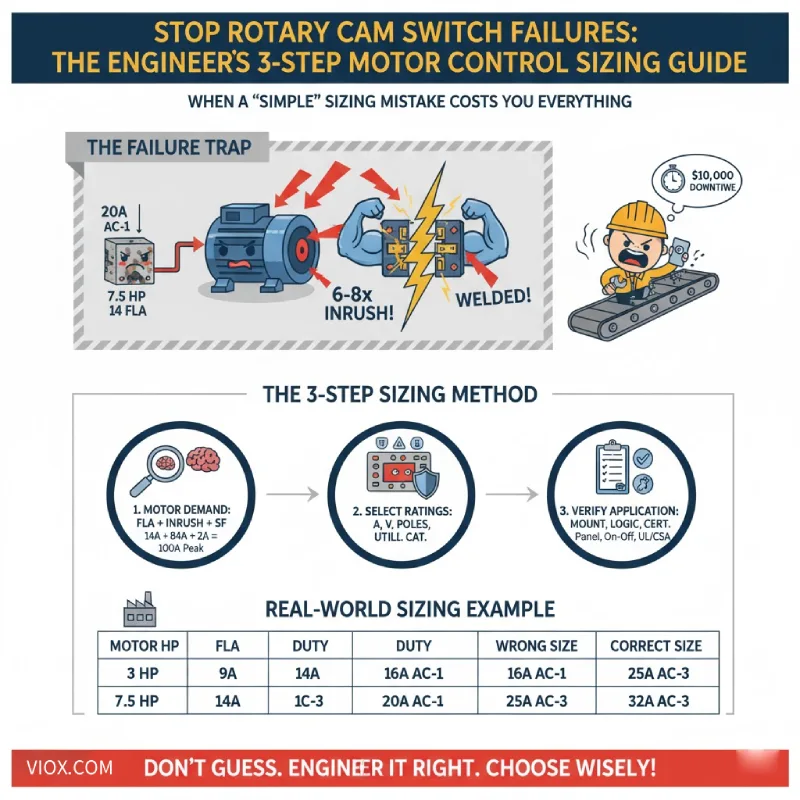
เมื่อข้อผิดพลาดในการกำหนดขนาด “ง่ายๆ” ทำให้คุณสูญเสียทุกอย่าง

คุณกำลังสรุปการออกแบบแผงควบคุมสำหรับสายการผลิตใหม่ ทีมงานเครื่องกลระบุว่ามอเตอร์สามเฟสขนาด 7.5 แรงม้าสำหรับสายพานลำเลียงหลัก และคุณได้คำนวณขนาดสายไฟ เลือกโอเวอร์โหลดรีเลย์ และเดินสายทุกอย่างตามข้อกำหนดอย่างพิถีพิถัน สวิตช์ลูกเบี้ยวแบบหมุนสำหรับการควบคุมมอเตอร์? คุณเลือกอันที่ได้รับการจัดอันดับไว้ที่ 20 แอมป์ ท้ายที่สุดแล้ว ป้ายชื่อมอเตอร์แสดง 14 FLA นั่นควรจะมีพื้นที่ว่างมากมายใช่ไหม?
สามเดือนหลังจากการทดสอบเดินเครื่อง คุณได้รับการติดต่อที่ไม่มีวิศวกรคนใดอยากได้ยิน: สายพานลำเลียงไม่หยุด สวิตช์ลูกเบี้ยวแบบหมุนมีการเชื่อมติดกัน มอเตอร์กำลังทำงานโดยไม่สามารถควบคุมได้ และสายการผลิตทั้งหมดถูกปิดเพื่อการบำรุงรักษาฉุกเฉิน การตรวจสอบหลังเกิดเหตุการณ์เผยให้เห็นหน้าสัมผัสสวิตช์ที่ไหม้เกรียมและค่าใช้จ่ายในการเปลี่ยนทดแทนที่สูงกว่าราคาเดิมถึง 10 เท่า โดยไม่นับรวมเวลาหยุดทำงาน.
แล้วอะไรคือสิ่งที่ผิดพลาด? และที่สำคัญกว่านั้น คุณจะกำหนดขนาดสวิตช์ลูกเบี้ยวแบบหมุนที่ไม่ล้มเหลวเมื่อมีความสำคัญมากที่สุดได้อย่างไร?
คำตอบไม่ได้ง่ายอย่างที่คิดว่า “จับคู่พิกัดแอมป์กับมอเตอร์” ในคู่มือนี้ คุณจะได้เรียนรู้วิธีการสามขั้นตอนที่วิศวกรผู้มีประสบการณ์ใช้ในการกำหนดขนาดสวิตช์ลูกเบี้ยวแบบหมุนสำหรับการควบคุมมอเตอร์ที่เชื่อถือได้ โดยคำนึงถึงความเป็นจริงทางไฟฟ้าที่เอกสารข้อมูลไม่ได้ระบุไว้อย่างชัดเจนเสมอไป.
ทำไม “พิกัดแอมป์” ไม่ได้หมายถึง “พิกัดมอเตอร์”
นี่คือความจริงที่โหดร้ายที่เป็นสาเหตุของความล้มเหลวของสวิตช์ลูกเบี้ยวแบบหมุนส่วนใหญ่: สวิตช์ไม่ได้แค่ส่งกระแสไฟฟ้า แต่ยังสร้างและตัดกระแสไฟฟ้าภายใต้ภาระ. และเมื่อภาระนั้นเป็นมอเตอร์ ความเค้นทางไฟฟ้าจะรุนแรง.
ลองพิจารณาดูว่าจะเกิดอะไรขึ้นในขณะที่คุณปิดสวิตช์บนวงจรมอเตอร์ มอเตอร์ “14 แอมป์” ที่คุณคำนวณไว้? ในระหว่างการสตาร์ทแบบ Direct-on-line มอเตอร์จะดึง 6 ถึง 8 เท่าของกระแสไฟฟ้าเต็มพิกัด เป็นเวลาหลายวินาทีในขณะที่โรเตอร์เร่งความเร็วจากจุดหยุดนิ่ง หน้าสัมผัสสวิตช์ของคุณต้องปิดเพื่อต้านทานกระแสไหลเข้าโดยไม่เชื่อมติดกัน และเปิดเพื่อต้านทานแรงดันไฟฟ้าเหนี่ยวนำย้อนกลับของมอเตอร์โดยไม่เกิดประกายไฟอย่างรุนแรงในภายหลัง.
นี่คือเหตุผลที่สวิตช์มี พิกัดประเภทการใช้งาน เช่น AC-1, AC-3 และ AC-4:
- AC-1: โหลดความต้านทาน (ฮีตเตอร์) ภาระงานเบา กระแสไหลเข้าน้อยที่สุด ไม่มีแรงดันไฟฟ้าเหนี่ยวนำย้อนกลับ.
- AC-3: การสตาร์ทและเดินเครื่องมอเตอร์กรงกระรอก รองรับกระแสไหลเข้า 6 เท่าเมื่อปิด ตัดที่กระแสไฟฟ้าขณะเดินเครื่อง.
- AC-4: ภาระงานหนัก การเสียบปลั๊กมอเตอร์ การกลับทิศทาง การเขย่า สร้างและตัดที่สูงถึง 6 เท่าของ FLA.
สวิตช์ที่ได้รับการจัดอันดับ “20A” สำหรับการใช้งาน AC-1 อาจรองรับมอเตอร์ขนาด 5 แรงม้าในการใช้งาน AC-3 เท่านั้น. ค่าแอมแปร์ที่ระบุเพียงอย่างเดียวไม่ได้บอกอะไรคุณเกี่ยวกับความสามารถในการควบคุมมอเตอร์.
กุญแจ Takeaway: หน้าสัมผัสสวิตช์ การออกแบบการระงับส่วนโค้ง และความทนทานทางกลแตกต่างกันระหว่างสวิตช์ “20A อเนกประสงค์” และสวิตช์ “20A AC-3 ควบคุมมอเตอร์” ตรวจสอบประเภทการใช้งานเสมอก่อนทำการเลือก.
วิธีการกำหนดขนาด สวิตช์ลูกเบี้ยวหมุน 3 ขั้นตอน


ทำตามกระบวนการที่เป็นระบบนี้เพื่อระบุสวิตช์ที่รองรับความเค้นทางไฟฟ้าในโลกแห่งความเป็นจริงของการควบคุมมอเตอร์ ไม่ใช่แค่ตัวเลขบนป้ายชื่อตามทฤษฎีเท่านั้น.
ขั้นตอนที่ 1: คำนวณความต้องการไฟฟ้าที่แท้จริงของมอเตอร์ของคุณ
อย่าเพียงแค่คัดลอก FLA จากป้ายชื่อมอเตอร์แล้วบอกว่าเสร็จแล้ว คุณต้องเข้าใจโปรไฟล์ไฟฟ้าที่สมบูรณ์ของมอเตอร์ของคุณ:
1.1 เริ่มต้นด้วยกระแสไฟฟ้าเต็มพิกัด (FLA)
ค้นหาสิ่งนี้บนป้ายชื่อมอเตอร์ที่แรงดันไฟฟ้าที่กำหนด ตัวอย่างเช่น:
- 3 แรงม้าที่ 208V = ~9A
- 7.5 แรงม้าที่ 415V = 10-14A
- 15 แรงม้าที่ 480V = 20-22A
1.2 พิจารณาวิธีการสตาร์ท
วิธีที่คุณสตาร์ทมอเตอร์มีผลกระทบอย่างมากต่อความเค้นของสวิตช์:
- Direct-On-Line (DOL): กระแสไหลเข้าเต็มที่กระทบสวิตช์ ต้องการมากที่สุดเมื่อปิด.
- Star-Delta: กระแสไหลเข้าต่ำกว่า แต่มีการสลับสองครั้งต่อการสตาร์ท.
- Soft Starter/VFD: การเพิ่มขึ้นแบบควบคุม แต่คุณยังคงต้องสลับกระแสไฟฟ้าขณะเดินเครื่องเต็มที่.
1.3 พิจารณาปัจจัยการใช้งาน
หากมอเตอร์ของคุณทำงานอย่างต่อเนื่องหรือใกล้เคียงกับภาระสูงสุด ให้ใช้ปัจจัยการใช้งาน วิศวกรหลายคนใช้ 1.15x ถึง 1.25x FLA เป็นกระแสไฟฟ้าในการออกแบบ.
มืออาชีพเคล็ดลับ: สำหรับมอเตอร์ขนาด 7.5 แรงม้าที่ 415V ที่ดึง 14A FLA ด้วยการสตาร์ท DOL สวิตช์ของคุณต้องรองรับกระแสไฟฟ้าต่อเนื่อง 14A บวกกับกระแสไหลเข้า 80-100A เป็นเวลาหลายวินาที สิ่งนี้บอกคุณได้ทันทีว่าสวิตช์ 16A มีขนาดเล็กเกินไป คุณต้องมีอย่างน้อย 25A ที่ได้รับการจัดอันดับสำหรับการใช้งาน AC-3.
ขั้นตอนที่ 2: เลือกสวิตช์ที่มีพิกัดที่ถูกต้อง
ตอนนี้จับคู่โปรไฟล์ของมอเตอร์ของคุณกับสวิตช์ที่สามารถรองรับได้ คุณกำลังตรวจสอบข้อกำหนดที่สำคัญสี่ประการ:
2.1 พิกัดกระแสไฟฟ้า (ปัดขึ้นเสมอ)
เลือกสวิตช์ที่มีพิกัดกระแสไฟฟ้าเท่ากับหรือมากกว่ากระแสไฟฟ้าขณะเดินเครื่องสูงสุดของมอเตอร์ของคุณโดยมีส่วนต่าง.
| แรงม้าของมอเตอร์ | Voltage | กระแสไฟฟ้าเต็มพิกัด | แอมแปร์ของสวิตช์ที่แนะนำ |
|---|---|---|---|
| 3 แรงม้า | 208 V | ~9A | 16 A |
| 7.5 แรงม้า | 415 V | ~10-14A | 25 A |
| 15 แรงม้า | 480 V | ~20-22A | 25-32 A |
กุญแจ Takeaway: ปัดขึ้นเป็นขนาดสวิตช์มาตรฐานที่ใกล้เคียงที่สุด หากมอเตอร์ของคุณดึงกระแส 22A ให้เลือก 25A หรือ 32A ห้ามเลือก 20A เด็ดขาด ขอบเขตนี้ป้องกันแรงดันไฟตกขณะสตาร์ท และให้พื้นที่ว่างทางความร้อนสำหรับการทำงานต่อเนื่อง.
2.2 พิกัดแรงดันไฟฟ้า (เท่ากับหรือสูงกว่า)
พิกัดแรงดันไฟฟ้าของสวิตช์ต้องเท่ากับหรือสูงกว่าแรงดันไฟฟ้าของแหล่งจ่ายมอเตอร์ของคุณ:
- มอเตอร์ 400V → สวิตช์ขั้นต่ำ 400V
- มอเตอร์ 480V → สวิตช์ 480V หรือ 600V
- ห้ามใช้สวิตช์ 400V กับวงจร 480V เด็ดขาด
2.3 การกำหนดค่าขั้ว
จับคู่ขั้วกับการกำหนดค่าเฟสของมอเตอร์ของคุณ:
- มอเตอร์เฟสเดียว: สวิตช์ 2 ขั้ว (สวิตช์ตัวนำสายทั้งสอง)
- มอเตอร์สามเฟส: สวิตช์ 3 ขั้ว (สวิตช์ทั้งสามเฟสพร้อมกัน)
สำคัญ: อย่าใช้สวิตช์ขั้วเดียวเพื่อควบคุมมอเตอร์สามเฟสโดยการสวิตช์เพียงเฟสเดียว สิ่งนี้จะสร้างความไม่สมดุลของเฟสและสามารถทำลายมอเตอร์ได้.
2.4 ประเภทการใช้งาน (ข้อกำหนดที่ซ่อนอยู่)
นี่คือจุดที่วิศวกรพลาด ตรวจสอบว่าสวิตช์ได้รับการจัดอันดับสำหรับหน้าที่เฉพาะของคุณ:
- การสตาร์ท/หยุด DOL มาตรฐาน: AC-3 ขั้นต่ำ
- การกลับด้าน การเสียบปลั๊ก หรือการควบคุมหลายความเร็ว: ต้องใช้ AC-4
- การสวิตช์เปิด-ปิดเท่านั้น (ไม่มีหน้าที่ในการสตาร์ท): AC-3 เพียงพอ
สวิตช์ที่ได้รับการจัดอันดับ “25A AC-1” อาจรองรับได้เพียง 12A ในหน้าที่ AC-3. ตรวจสอบตารางพิกัดการควบคุมมอเตอร์ของผู้ผลิตเสมอ อย่าคิดว่าพิกัดที่ระบุมีผลบังคับใช้.
ขั้นตอนที่ 3: ตรวจสอบข้อกำหนดเฉพาะของแอปพลิเคชัน
คุณได้รับการจัดอันดับทางไฟฟ้าที่ถูกต้องแล้ว ตอนนี้ยืนยันข้อกำหนดทางกายภาพและสิ่งแวดล้อม:
3.1 การติดตั้งและกล่องหุ้ม
- การติดตั้งบนแผง: ด้านหน้าประตูพร้อมที่จับสำหรับใช้งาน
- ราง DIN: ประหยัดพื้นที่สำหรับแผงควบคุมที่มีความหนาแน่น
- ปิดล้อม: IP65/NEMA 4 สำหรับสภาพแวดล้อมที่มีฝุ่นหรือมีการล้าง
3.2 ตรรกะการควบคุมและตำแหน่ง
- 2 ตำแหน่ง (เปิด-ปิด): เริ่ม/หยุดง่ายๆ
- 3 ตำแหน่ง (ปิด-1-2): มอเตอร์สองความเร็ว การเปลี่ยนแบบสตาร์-เดลต้า
- สปริงกลับสู่ศูนย์: หน้าสัมผัสคงที่สำหรับการทำงาน, ชั่วขณะสำหรับการเขย่า
- สามารถใส่กุญแจได้: การล็อก/ติดป้ายเพื่อความปลอดภัยสำหรับการบำรุงรักษา
3.3 การรับรองและการปฏิบัติตามข้อกำหนด
ตรวจสอบว่าสวิตช์ได้รับการรับรองสำหรับเขตอำนาจศาลของคุณ:
- อเมริกาเหนือ: รายการ UL/CSA
- ยุโรป: เป็นไปตามมาตรฐาน IEC/EN 60947-3
- สภาพแวดล้อมทางอุตสาหกรรม: ตรวจสอบพิกัด UL 508 หรือ IEC 60947-5-1
มืออาชีพเคล็ดลับ: หากแอปพลิเคชันของคุณเกี่ยวข้องกับการกลับด้านหรือการควบคุมแบบสตาร์-เดลต้า คุณต้องมีสวิตช์ลูกเบี้ยวที่มีลำดับลูกเบี้ยวภายในที่ถูกต้อง สวิตช์เปิด-ปิดมาตรฐานจะไม่ทำงาน ลูกเบี้ยวต้องตัด L1-L2-L3 ตามลำดับที่ถูกต้องเพื่อป้องกันการทับซ้อนของเฟสระหว่างการเปลี่ยน.
ตัวอย่างการปรับขนาดในโลกแห่งความเป็นจริง
มาดูข้อกำหนดที่สมบูรณ์กัน:
โปรแกรม: มอเตอร์สามเฟส 10 HP, 460V, การสตาร์ทแบบ Direct-on-line สำหรับระบบสายพานลำเลียงในสภาพแวดล้อมการผลิตที่สะอาด.
ขั้นตอนที่ 1 – ความต้องการของมอเตอร์:
- Nameplate FLA ที่ 460V: ~14A
- กระแสไหลเข้าเริ่มต้น DOL: ~6x = 84A เป็นเวลา 3-5 วินาที
- Service factor: 1.15x = กระแสออกแบบ 16A
ขั้นตอนที่ 2 – การเลือกสวิตช์:
- พิกัดกระแสไฟ: 25A (ขนาดถัดไปจาก 16A)
- พิกัดแรงดันไฟฟ้า: 600V (เกินข้อกำหนด 460V)
- การกำหนดค่าขั้ว: 3 ขั้ว (มอเตอร์สามเฟส)
- ประเภทการใช้งาน: AC-3 ที่ได้รับการจัดอันดับสำหรับหน้าที่ในการสตาร์ทมอเตอร์
ขั้นตอนที่ 3 – รายละเอียดแอปพลิเคชัน:
- การติดตั้ง: ด้านหน้าแผงพร้อมที่จับแบบหมุน
- ตำแหน่ง: 2 ตำแหน่ง (ปิด-ทำงาน) ไม่มีสปริงกลับ
- สภาพแวดล้อม: IP20 (สภาพแวดล้อมภายในอาคารที่สะอาด)
- การรับรอง: ได้รับการรับรองตามมาตรฐาน UL 508 สำหรับการควบคุมทางอุตสาหกรรม
ผลลัพธ์: ระบุสวิตช์ลูกเบี้ยวแบบหมุน 25A, 3 ขั้ว, 600V ที่ได้รับการจัดอันดับ AC-3 สำหรับการควบคุมมอเตอร์, พร้อมการติดตั้งบนแผงด้านหน้าและการทำงานแบบ 2 ตำแหน่ง Off-Run.
ประเด็นสำคัญ: ทำไมการกำหนดขนาดที่เหมาะสมจึงมีความสำคัญ
โดยการทำตามวิธีสามขั้นตอนต่อไปนี้—การคำนวณความต้องการมอเตอร์ที่แท้จริง, การเลือกสวิตช์ที่มีพิกัดและประเภทการใช้งานที่ถูกต้อง, และการตรวจสอบรายละเอียดเฉพาะของการใช้งาน—คุณจะกำจัดโหมดความล้มเหลวที่พบบ่อยที่สุดสามประการ:
- ✓ หน้าสัมผัสเชื่อมติดกันจากกระแสไหลเข้า: พิกัด AC-3/AC-4 ที่เหมาะสมรองรับหน้าที่การสับและตัดวงจร
- ✓ ความร้อนสูงเกินไปจากการกำหนดขนาดต่ำกว่าที่ควร: ค่าเผื่อกระแสที่เพียงพอป้องกันความร้อนสูงเกินไปเรื้อรัง
- ✓ ความเสียหายจากส่วนโค้งไฟฟ้าจากพิกัดหน้าที่ที่ไม่เหมาะสม: การจับคู่ประเภทการใช้งานช่วยให้มั่นใจได้ว่าวัสดุหน้าสัมผัสสามารถรับมือกับความเค้นได้
สวิตช์ลูกเบี้ยวแบบหมุนที่มีขนาดเหมาะสมไม่ได้เป็นเพียงแค่การปฏิบัติตามข้อกำหนด—แต่เป็นการออกแบบระบบควบคุมที่ไม่ล้มเหลว. ความแตกต่างของต้นทุนเริ่มต้นระหว่างสวิตช์ 20A และ 25A นั้นน้อยมาก ต้นทุนในการเปลี่ยนสวิตช์ที่เชื่อมติดกัน, การหยุดทำงานฉุกเฉิน, และเหตุการณ์ด้านความปลอดภัยที่อาจเกิดขึ้น? นั่นคือสิ่งที่ทำให้คุณนอนไม่หลับในตอนกลางคืน.
แผงควบคุมมอเตอร์ตัวต่อไปของคุณสมควรได้รับสิ่งที่ดีกว่าการคาดเดา. ใช้วิธีนี้, ตรวจสอบประเภทการใช้งานของคุณ, และปัดเศษขึ้นเสมอ ตัวคุณในอนาคต—และผู้จัดการฝ่ายผลิตของคุณ—จะขอบคุณคุณ.
