
The Monday Morning Catastrophe

It’s 6:47 AM on Monday, and your phone is already ringing. The plant manager’s voice is tight with panic: “The main production line is down. The VFD is completely fried—circuit boards are black, and there’s a burnt smell throughout the electrical room.”
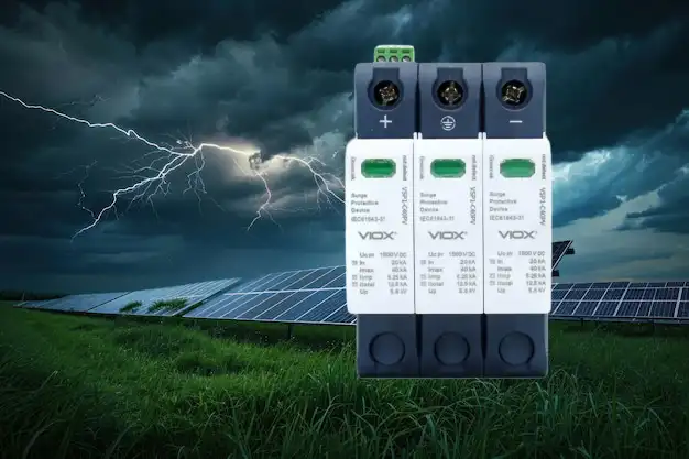
You rush to the site. Weekend thunderstorms rolled through, and a nearby lightning strike sent a massive surge through the facility’s power system. As you stare at the charred remains of a $52,000 variable frequency drive, you notice something that makes your stomach drop: there’s a surge protector installed right there in the panel—a $300 device that was supposed to prevent exactly this disaster.
But it didn’t work. The equipment died anyway.
The plant manager asks the question you’re dreading: “I thought we installed surge protection last year. Why didn’t it work? And how do we make sure this never happens again?”
Why “Installing a Surge Protector” Isn’t Enough

Here’s the brutal truth that most engineers learn the expensive way: Not all surge protective devices (SPDs) are created equal, and installation alone doesn’t guarantee protection.
The SPD that failed to protect your VFD? After investigation, you discover three critical mistakes:
- Wrong voltage rating – The SPD’s maximum continuous working voltage (Uc) was 385V, but transient overvoltages in your system regularly spike to 420V during motor starting, causing the SPD to degrade prematurely
- Insufficient discharge capacity – The SPD was rated for 40 kA (Imax), but the installation location—near the service entrance in an industrial facility with overhead lines—needed 100 kA to handle lightning-induced surges
- Poor protection distance – The SPD was mounted at the main distribution panel 150 feet away from the VFD, allowing induced voltages to develop along the cable run and bypass the protection entirely
Each mistake alone could compromise protection. Together, they guaranteed failure.
The core problem? SPD selection isn’t about buying “a surge protector”—it’s about engineering a protection system that matches your specific application parameters. Miss even one parameter, and you’re gambling with six-figure equipment.
သော့ယူသွားခြင်း- An SPD can only protect what it’s properly rated and positioned to protect. Wrong ratings or installation location = zero protection, regardless of brand name or price tag. The selection process matters more than the product itself.
The Solution: Master the 6-Parameter Selection Method
The answer isn’t complicated, but it requires a systematic approach. Professional electrical engineers use a 6-step method based on IEC and GB/T standards that considers voltage ratings, discharge capacity, protection levels, and system coordination. This isn’t guesswork—it’s engineering.
Here’s what this method delivers:
- Match SPD ratings to actual system conditions – not generic “industrial” specs
- Prevent nuisance tripping that shuts down production
- Coordinate multiple protection stages without complex spacing calculations
- Extend SPD lifespan by selecting appropriate discharge ratings
- Pass inspection with properly documented protection engineering
Let’s break down the six-step process that ensures your SPD actually protects equipment instead of giving you false confidence.
Step 1: Calculate the Four Critical Voltage and Current Parameters
Most engineers start SPD selection by asking “what kA rating do I need?” Wrong starting point. You must first establish the voltage environment, then determine discharge capacity.
Parameter 1: Maximum Continuous Working Voltage (Uc) – Your First Line of Defense
What it is: The highest RMS voltage the SPD can withstand continuously without degrading or failing.
ရေးပါအဘယ်ကြောင့်: If your system voltage exceeds Uc—even momentarily during normal operations—the SPD begins to fail. This isn’t a surge event; this is regular system voltage killing your protection.
How to calculate it correctly:
For a 400V three-phase system (phase-to-neutral = 230V):
- Minimum Uc required: System voltage × 1.1 = 230V × 1.1 = 253V minimum
- Recommended Uc: System voltage × 1.15 to 1.2 = 230V × 1.2 = 276V recommended
The mistake engineers make: Selecting an SPD with Uc = 255V for a 230V system seems adequate on paper, but transient overvoltages (TOVs) during capacitor switching or ground faults can push system voltage to 250V for several seconds. Your SPD is now operating at its absolute limit during what should be routine operations.
-အစွန်အဖျား: Always select Uc at least 15-20% above your nominal system voltage. For 230V systems, choose Uc ≥ 275V. For 480V systems (277V phase-to-neutral), choose Uc ≥ 320V. This margin accounts for TOVs and extends SPD lifespan dramatically.
Parameter 2: Temporary Overvoltage Withstand (UT) – Surviving System Faults
What it is: The SPD’s ability to withstand temporary overvoltages that occur during ground faults or neutral loss in the low-voltage system.
Real-world scenario: A phase-to-ground fault upstream causes the healthy phases to rise to phase-to-phase voltage (400V instead of 230V) for 1-5 seconds until protective devices clear the fault. Your SPD must survive this without conducting or failing.
Specification requirement: UT value must exceed the expected TOV magnitude and duration in your system. For TN-S systems, this is typically 1.45 × Un for 5 seconds. For TN-C systems or systems with uncertain grounding, use 1.55 × Un.
Parameter 3 & 4: Discharge Currents (In, Iimp, Imax) – Matching Threat Level
ဤ parameters သုံးခုသည် SPD ၏ surge စွမ်းအင်ကို ကိုင်တွယ်နိုင်စွမ်းကို သတ်မှတ်သည်။
- In (nominal discharge current) အမျိုးအစားခွဲခြားစမ်းသပ်ခြင်းအတွက်အသုံးပြုသည်။ Class II SPDs အတွက် 20 kA
- Iimp (impulse current) ဝန်ဆောင်မှုအဝင်အနီးရှိ Class I SPDs အတွက်လိုအပ်သည်။ 12.5 kA, 25 kA, သို့မဟုတ် 50 kA
- Imax (maximum discharge current) SPD သည် ရှင်သန်နိုင်သည့် အမြင့်ဆုံးပမာဏဖြစ်သည်။ သက်တမ်းကို ဆုံးဖြတ်သည်။
မှန်ကန်သောတန်ဖိုးများကို မည်သို့ရွေးချယ်ရမည်နည်း။
| တပ်ဆင်ခြင်းတည်နေရာ | ထိတွေ့မှုအဆင့် | လိုအပ်သော အနည်းဆုံး Imax |
|---|---|---|
| ဝန်ဆောင်မှုအဝင်၊ လျှပ်စစ်ဓာတ်အားလိုင်းများ၊ မိုးကြိုးအန္တရာယ်ရှိသောနေရာ | မြင့် | 100 kA (Iimp ပါသော Class I) |
| ပင်မဖြန့်ဖြူးရေး panel၊ စက်မှုလုပ်ငန်းသုံး အဆောက်အဦ | လတ် | 60-80 kA (Class I သို့မဟုတ် II) |
| ခွဲဖြန့်ဖြူးရေး၊ ထိလွယ်ရှလွယ်ပစ္စည်းကိရိယာအနီး | အနိမ့် | 40 kA (Class II) |
| ပစ္စည်းကိရိယာတွင် နောက်ဆုံးကာကွယ်မှု | အလွန်နိမ့်သည်။ | 20 kA (Class III) |
အရေးကြီးသောအချက်အလက် Imax မြင့်လေလေ၊ ထပ်ခါထပ်ခါ surge ဖိအားအောက်တွင် SPD သက်တမ်းပိုရှည်လေဖြစ်သည်။ 100 kA အဆင့်သတ်မှတ်ထားသော SPD သည် တူညီသောအသုံးချမှုတွင် 40 kA SPD ထက် 3-5 ဆ ပိုကြာရှည်ခံမည်ဖြစ်ပြီး၊ အမှန်တကယ် surges များသည် 30 kA ထက်မပိုလျှင်ပင်။ အပိုပမာဏသည် အရေးကြီးသည်။.
အဆင့် ၂- ကာကွယ်ရေးအကွာအဝေးကို ဆုံးဖြတ်ပါ (လူတိုင်းလျစ်လျူရှုထားသော ၁၀ မီတာ စည်းမျဉ်း)
ဤနေရာတွင် တပ်ဆင်မှုအများစုသည် ကျရှုံးရခြင်းဖြစ်သည်- ပင်မ panel ရှိ SPD သည် မီတာ ၅၀ အကွာအဝေးရှိ ပစ္စည်းကိရိယာကို မကာကွယ်နိုင်ပါ။.
ကာကွယ်ရေးအကွာအဝေးကို နားလည်ခြင်း
surge သည် သင့်စနစ်ကို ထိမှန်သောအခါ၊ ၎င်းသည် လှိုင်းတစ်ခုအဖြစ် ရွေ့လျားသည်။ SPD သည် ကာကွယ်ထားသော ပစ္စည်းကိရိယာနှင့် ဝေးကွာပါက၊ ကေဘယ်ကြိုးတစ်လျှောက်ရှိ ရောင်ပြန်ဟပ်မှုများနှင့် inductive coupling သည် SPD ကန့်သတ်ထားသည်ထက် ပိုများသော ပစ္စည်းကိရိယာ terminals များတွင် ဗို့အား “overshoot” ကို ဖန်တီးပေးသည်။.
ရူပဗေဒ SPD နှင့် ပစ္စည်းကိရိယာကြားရှိ ကေဘယ်ကြိုး ၁၀ မီတာတိုင်းအတွက်၊ လျင်မြန်သော transients များအတွင်း အပိုဗို့အားဖိအား ၁ kV ခန့်ကို ထည့်ပါ။.
ဥပမာ တွက်ချက်မှု-
SPD ဗို့အားကာကွယ်မှုအဆင့် (Up): 1.5 kV
ပစ္စည်းကိရိယာသို့ ကေဘယ်အကွာအဝေး: ၄၀ မီတာ
ထပ်ဆောင်းဖြစ်ပေါ်သောဗို့အား: 40m ÷ 10m × 1 kV = 4 kV
ပစ္စည်းကိရိယာ terminals များတွင် အမှန်တကယ်ဗို့အား 1.5 kV + 4 kV = 5.5 kV
သင့် VFD ၏ impulse ခံနိုင်ရည်သည် 4 kV (စက်မှုလုပ်ငန်းသုံးပစ္စည်းများအတွက် ပုံမှန်) ဖြစ်ပါက၊ SPD ရှိနေသော်လည်း ၎င်းသည် ကျရှုံးသည်။.
သုံးဇုန် ကာကွယ်ရေးနည်းဗျူဟာ
ထိလွယ်ရှလွယ်ပစ္စည်းကိရိယာအတွက်၊ cascaded ကာကွယ်မှုကို အသုံးပြုပါ-
ဇုန် ၁ – ဝန်ဆောင်မှုအဝင် SPD (Class I)
- တည်နေရာ- ပင်မဖြန့်ဖြူးရေးဘုတ်အဖွဲ့
- အဆင့်သတ်မှတ်ချက်- Iimp = 25-50 kA, Up = 2.5 kV
- ရည်ရွယ်ချက်- ကြီးမားသော ပြင်ပ surges (မိုးကြိုး) ကို စုပ်ယူပါ။
ဇုန် ၂ – ဖြန့်ဖြူးရေးဘုတ်အဖွဲ့ SPD (Class II)
- တည်နေရာ- ထိလွယ်ရှလွယ်ဝန်များကို ကျွေးမွေးသော ခွဲဖြန့်ဖြူးရေး
- အဆင့်သတ်မှတ်ချက်- Imax = 40-60 kA, Up = 1.5 kV
- ဇုန် ၁ မှ အကွာအဝေး- >၁၀ မီတာ (သို့မဟုတ် auto-coordinating SPDs ကို အသုံးပြုပါ)
- ရည်ရွယ်ချက်- ဗို့အားဖိအားကို ထပ်မံလျှော့ချပါ။
ဇုန် ၃ – ပစ္စည်းကိရိယာ SPD (Class III)
- တည်နေရာ- ပစ္စည်းကိရိယာ terminals များတွင် တပ်ဆင်ထားသည်။
- အဆင့်သတ်မှတ်ချက်- Imax = 20 kA, Up = 1.0 kV
- ပစ္စည်းကိရိယာမှ အကွာအဝေး- <၅ မီတာ
- ရည်ရွယ်ချက်- ပစ္စည်းကိရိယာ ခံနိုင်ရည်အဆင့်သို့ နောက်ဆုံးကာကွယ်မှု
-အစွန်အဖျား: အလိုအလျောက် စွမ်းအင်ညှိနှိုင်းမှုလုပ်ဆောင်ချက်များပါရှိသော ခေတ်မီ SPDs များသည် အဆင့်များကြားရှိ “၁၀ မီတာ စည်းမျဉ်း” နေရာချထားမှုလိုအပ်ချက်ကို ဖယ်ရှားပေးသည်။ ၎င်းတို့သည် ကေဘယ် impedance ကို အားမကိုးဘဲ စွမ်းအင်မျှဝေမှုကို ညှိနှိုင်းရန်အတွက် built-in decoupling ကို အသုံးပြုသည်။ နေရာချထားမှုကို ထိန်းသိမ်းရန် မဖြစ်နိုင်သည့် retrofit applications များအတွက်၊ auto-coordinating SPDs ကို သတ်မှတ်ပါ—၎င်းသည် 20-30% ပိုပေးရကျိုးနပ်ပါသည်။.
အဆင့် ၃- ပစ္စည်းကိရိယာ ခုခံအားအပေါ် အခြေခံ၍ ဗို့အားကာကွယ်မှုအဆင့် (Up) ကို ရွေးချယ်ပါ
ဗို့အားကာကွယ်မှုအဆင့် (Up) သည် အရေးအကြီးဆုံး SPD သတ်မှတ်ချက်, ဖြစ်သော်လည်း ၎င်းကို မကြာခဏ လျစ်လျူရှုထားကြသည်။ ၎င်းသည် surge တစ်ခုအတွင်း သင့်ပစ္စည်းကိရိယာမြင်ရသည့် အမှန်တကယ်ဗို့အားဖြစ်သည်။.
ပစ္စည်းကိရိယာ ခံနိုင်ရည်ဗို့အားနှင့် ကိုက်ညီခြင်း
အခြေခံစည်းမျဉ်း SPD ဗို့အားကာကွယ်မှုအဆင့် (Up) သည် ပစ္စည်းကိရိယာ၏ impulse ခံနိုင်ရည်ဗို့အား (Uw) ထက် သိသိသာသာ နိမ့်ရမည်။.
အကြံပြုထားသော ဘေးကင်းလုံခြုံရေးအချက် Up ≤ 0.8 × Uw
အသုံးများသော ပစ္စည်းကိရိယာ impulse ခံနိုင်ရည်ဗို့အားများ
| ပစ္စည်းကိရိယာ အမျိုးအစား | IEC 60364-4-44 အရ အမျိုးအစား | Impulse ခံနိုင်ရည် (Uw) |
|---|---|---|
| ထိလွယ်ရှလွယ် အီလက်ထရောနစ်ပစ္စည်းများ၊ PLCs၊ တူရိယာများ | အမျိုးအစား I | 1.5 kV |
| ဖြန့်ဖြူးရေးဘုတ်များ၊ စက်မှုသုံးပစ္စည်းများ | အမျိုးအစား II | 2.5 kV |
| တပ်ဆင်ပြီး စက်မှုသုံးပစ္စည်းများ | အမျိုးအစား III | 4.0 kV |
| ဝန်ဆောင်မှုပေးသော ပစ္စည်းများ | အမျိုးအစား IV | 6.0 kV |
VFD ကာကွယ်မှုအတွက် ရွေးချယ်မှု ဥပမာ-
VFD လျှပ်စီးဒဏ်ခံနိုင်မှု: 4.0 kV (အမျိုးအစား III)
လိုအပ်သော Up: ≤ 0.8 × 4.0 kV = အများဆုံး 3.2 kV
ဒါပေမယ့် ဒီမှာ ပိုပြီးအဆင့်မြင့်တဲ့အပိုင်းက: Up တန်ဖိုးများ နည်းလေလေ ကာကွယ်မှု ပိုကောင်းလေလေဖြစ်သော်လည်း အရည်အသွေးမြင့် SPD အစိတ်အပိုင်းများ လိုအပ်ပြီး ကုန်ကျစရိတ် ပိုများလေလေဖြစ်သည်။.
SPD Up နှိုင်းယှဉ်ချက်:
- စံ SPD: Up = 2.5 kV, ကုန်ကျစရိတ် အခြေခံ
- မြှင့်တင်ထားသော SPD: Up = 1.5 kV, ကုန်ကျစရိတ် +30%
- ပရီမီယံ SPD: Up = 1.0 kV, ကုန်ကျစရိတ် +60%
ဆုံးဖြတ်ချက် မူဘောင်:
- 5,000 အောက် စက်ပစ္စည်းများအတွက်: Up ≤ 2.5 kV လက်ခံနိုင်သည်
- 5,000-50,000 ကြား စက်ပစ္စည်းများအတွက်: Up ≤ 1.5 kV အကြံပြုသည်
- အရေးကြီးသော စက်ပစ္စည်းများ 50,000 ကျော်အတွက်: Up ≤ 1.0 kV ကို အထူးအကြံပြုသည်
သော့ယူသွားခြင်း- Up တန်ဖိုး နည်းလေလေ ကာကွယ်မှု ပိုကောင်းလေလေဖြစ်သော်လည်း အကျိုးအမြတ် လျော့နည်းလာသည်။ Up = 2.5 kV မှ 1.5 kV သို့ ပြောင်းခြင်းသည် ဈေးကြီးသော စက်ပစ္စည်းများအတွက် တန်ဖိုးရှိသည်။ 1.5 kV မှ 1.0 kV သို့ ပြောင်းခြင်းသည် စက်ပစ္စည်းသည် အလွန်ထိလွယ်ရှလွယ် (အမျိုးအစား I) မဟုတ်ပါက အပိုအကျိုးအမြတ် အနည်းငယ်သာ ပေးသည်။.
အဆင့် 4: Zero-Leakage SPDs ဖြင့် အနှောင့်အယှက်ဖြစ်စေသော ခရီးစဉ်များကို ဖယ်ရှားပါ
သင်သည် ပြီးပြည့်စုံသော အဆင့်သတ်မှတ်ချက်များဖြင့် SPD ကို ရွေးချယ်ပြီးပြီ။ သင်သည် ၎င်းကို ကုဒ်အလိုက် ထည့်သွင်းသည်။ ထို့နောက် လျှို့ဝှက်ဆန်းကြယ်စွာပင်၊, သင်၏ RCDs (ကျန်ရှိသော လျှပ်စီးကြောင်း ကိရိယာများ) သည် ကျပန်း ခရီးစတင်နေပြီ, ထုတ်လုပ်မှုကို ရပ်ဆိုင်းလိုက်သည်။.
ယိုစိမ့်မှု လျှပ်စီးကြောင်း ပြဿနာ
သတ္တုအောက်ဆိုဒ် ဗာရစ္စတာ (MOVs) သို့မဟုတ် ဓာတ်ငွေ့ထုတ်လွှတ်ပြွန် (GDTs) ကို အသုံးပြုထားသော ရိုးရာ SPDs များတွင် မူလယိုစိမ့်မှု လျှပ်စီးကြောင်း ရှိသည် - လျှပ်စီးကြောင်း မရှိသည့်တိုင်အောင် မြေပြင်သို့ အဆက်မပြတ် စီးဆင်းနေသော လျှပ်စီးကြောင်း အနည်းငယ် (ပုံမှန်အားဖြင့် 0.5-2 mA)။.
ဤအရာသည် အဘယ်ကြောင့် ပြဿနာများ ဖြစ်စေသနည်း။
- RCD အနှောင့်အယှက် ခရီးစဉ်: သင့်တွင် စနစ်တစ်ခုတွင် SPD 5-10 ခုရှိပါက စုစုပေါင်း ယိုစိမ့်မှု လျှပ်စီးကြောင်းသည် 10-20 mA သို့ရောက်ရှိနိုင်ပြီး RCD ခရီးစဉ် အကန့်အသတ် (ဝန်ထမ်းကာကွယ်မှုအတွက် ပုံမှန်အားဖြင့် 30 mA) နှင့် နီးကပ်လာသည်
- စဉ်ဆက်မပြတ် ပါဝါသုံးစွဲမှု: 2 mA × 230V × 24 နာရီ × 365 ရက် = SPD တစ်ခုလျှင် တစ်နှစ်လျှင် 4 kWh။ SPD 50 ပါသော အဆောက်အဦကြီးတစ်ခုတွင် တစ်နှစ်လျှင် 200 kWh ဖြုန်းတီးနေသည်
- SPD အိုမင်းခြင်း အစောပိုင်း: စဉ်ဆက်မပြတ် ယိုစိမ့်မှုသည် MOV ဒြပ်စင်များ၏ တဖြည်းဖြည်း ယိုယွင်းပျက်စီးမှုကို ဖြစ်စေသည်
ဖြေရှင်းချက်: ပေါင်းစပ် SPD နည်းပညာ
စဉ်ဆက်မပြတ် လျှပ်စီးကြောင်း သုညရှိသော ပေါင်းစပ် SPDs နည်းပညာများ ပေါင်းစပ်အသုံးပြုသည်:
- GDT (ဓာတ်ငွေ့ထုတ်လွှတ်ပြွန်) မူလဒြပ်စင်အဖြစ်: ပြိုကွဲသည်အထိ ယိုစိမ့်မှု သုည
- MOV (သတ္တုအောက်ဆိုဒ် ဗာရစ္စတာ) ချိတ်ဆက်ဒြပ်စင်အဖြစ်: GDT မီးလောင်ပြီးနောက် ဗို့အားကို ကန့်သတ်သည်
- အပူပိုင်း ဖြုတ်တပ်ခြင်း: ပျက်ကွက်သော အစိတ်အပိုင်းများကို သီးခြားခွဲထုတ်သည်
နည်းပညာဆိုင်ရာ အားသာချက်: လျှပ်စီးဗို့အားသည် ၎င်း၏ ပြိုကွဲမှုအဆင့် (ပုံမှန်အားဖြင့် 600-900V) သို့ရောက်ရှိသည်အထိ GDT တွင် အကန့်အသတ်မရှိ ခုခံမှုရှိသည်။ ဤအကန့်အသတ်အောက်တွင် လျှပ်စီးကြောင်း သုည စီးဆင်းသည် - ယိုစိမ့်မှုပြဿနာကို ဖြေရှင်းပေးသည်။.
-အစွန်အဖျား: RCDs ပါသော စနစ်များအတွက် သို့မဟုတ် အနှောင့်အယှက်ဖြစ်စေသော ခရီးစဉ်ကို လက်မခံနိုင်သော အသုံးချပရိုဂရမ်များ (ဆေးရုံများ၊ ဒေတာစင်တာများ၊ စဉ်ဆက်မပြတ် လုပ်ငန်းစဉ်များ) တွင် SPDs ကို သတ်မှတ်သည့်အခါ သင့်သတ်မှတ်ချက်တွင် “ယိုစိမ့်မှု လျှပ်စီးကြောင်း သုည” သို့မဟုတ် “GDT မူလဒြပ်စင်ပါသော ပေါင်းစပ် SPD” လိုအပ်သည်။ ကုန်ကျစရိတ် ပရီမီယံ 15-25% ကို ပထမဆုံး ရှောင်ရှားနိုင်သော ပိတ်သိမ်းမှုတွင် ပြန်လည်ရရှိသည်။.
အဆင့် 5: SPD ပျက်ကွက်မှုပုံစံနှင့် အရန်ကာကွယ်ရေးကို စီစဉ်ပါ
ဒီမှာ မသက်မသာဖြစ်စရာ အမှန်တရားတစ်ခုရှိတယ်: SPDs အားလုံးသည် နောက်ဆုံးတွင် ပျက်ကွက်သည်။. မေးခွန်းမှာ “ဘယ်အချိန်မှာ” မဟုတ်ဘဲ “ဘယ်အချိန်မှာ” - ပိုအရေးကြီးတာက “သူတို့လုပ်တဲ့အခါ ဘာဖြစ်မလဲ” ဆိုတာပါပဲ။”
SPD ပျက်ကွက်မှုပုံစံများ (အစွန်းနှစ်ဖက်)
SPD သည် ၎င်း၏ အများဆုံးအဆင့်သတ်မှတ်ချက်ထက် ကျော်လွန်သော လျှပ်စီးကြောင်းတစ်ခုနှင့် ထိတွေ့သောအခါ ၎င်းသည် နည်းလမ်းနှစ်ခုထဲမှ တစ်ခုဖြင့် ပျက်ကွက်သည်:
- ပွင့်လင်းဆားကစ် ပျက်ကွက်မှု (လုံခြုံ):
SPD သည် ဆားကစ်မှ ချိတ်ဆက်မှု ပြတ်တောက်သွားသည်
မီးဘေးအန္တရာယ် မရှိပါ
စနစ်သည် ဆက်လက်လည်ပတ်နေသည် (သို့သော် လျှပ်စီးကြောင်းကာကွယ်မှုမရှိဘဲ)
အားနည်းချက်: You don’t know protection is gone until equipment fails - Short-circuit failure (dangerous):
SPD becomes a low-resistance path to ground
Massive fault current flows (potentially thousands of amps)
Without proper backup protection: Cable overheats, panel fire starts
With backup protection: Upstream breaker trips, entire system shuts down
The Solution: SPD-Specific Backup Protector (SSD)
A standard circuit breaker or fuse is မ adequate backup protection for an SPD. Here’s why:
Standard circuit breaker limitations:
- Trip time: 100-500 ms at high fault current
- During this time: 10-50 kA flowing through failed SPD
- Result: SPD explodes, fire starts, or panels are damaged before breaker trips
SPD-specific backup protector (SSD):
- ပိုမြန်သောတုံ့ပြန်မှု- Clears fault in <10 ms
- Higher interrupt rating: Rated for 50-100 kA interrupt capacity
- SPD-coordinated: Allows normal SPD operation but trips immediately on failure
- Visual indication: Shows when SPD has failed and been disconnected
Selection criteria for SSD:
| SPD Max Discharge Current (Imax) | Minimum SSD Rating Required |
|---|---|
| 40 kA | 63A, 50 kA interrupt |
| 65 kA | 100A, 65 kA interrupt |
| 100 kA | 125A, 100 kA interrupt |
-အစွန်အဖျား: The SSD should be rated for the SPD’s maximum discharge current (Imax), not the circuit’s normal operating current. A common mistake is installing a 20A circuit breaker to protect a 65 kA SPD—this breaker will either nuisance-trip during surges or fail to protect during SPD short-circuit failure.
Step 6: Coordinate Multiple SPD Stages (Without Complex Calculations)
For multi-stage protection (service entrance + distribution + equipment), the SPDs must coordinate properly. If they don’t, one SPD absorbs all the energy while others never engage—defeating the entire protection strategy.
Traditional Coordination: The 10-15 Meter Rule
Classic approach requires physical separation between SPD stages:
- Zone 1 to Zone 2: Minimum 10 meters of cable
- Zone 2 to Zone 3: Minimum 10 meters of cable
Why separation works: Cable inductance (typically 1 μH/m) creates a “decoupling” effect that causes upstream SPDs to see higher voltage and conduct first, sharing energy burden.
The problem with this approach:
- Modern facilities have compact electrical rooms
- Cable routing may not allow 10+ meter separation
- Complex calculations required to verify coordination
- Field modifications often impossible
Modern Solution: Auto-Coordinating SPDs
Automatic energy coordination function eliminates spacing requirements through internal design:
How it works:
- Each SPD stage has built-in series impedance (inductors or resistors)
- This impedance is calibrated to create voltage division during surges
- Result: Upstream SPD always conducts first, regardless of physical separation
Selection advantage:
- Can install Zone 1 and Zone 2 SPDs in the same panel
- No field calculations needed
- Proven coordination per manufacturer testing
- Simplifies retrofit applications
Specification language: “SPD shall include automatic energy coordination function per [manufacturer standard], allowing installation at any distance from upstream protection without additional coordination calculations.”
Cost impact: Auto-coordinating SPDs cost 25-40% more than standard SPDs, but this premium is typically less than the labor cost of routing 10+ meters of additional cable to achieve spacing.
The Complete SPD Selection Checklist
Pulling it all together, here’s your specification checklist for specifying SPDs that actually protect equipment:
လျှပ်စစ်ဆိုင်ရာသတ်မှတ်ချက်များ (အဆင့် ၁):
- ☑ Uc (အများဆုံးဆက်တိုက်ဗို့အား): ≥ 1.15 × စနစ်၏ပုံမှန်ဗို့အား
- ☑ UT (ယာယီဗို့အားပိုလျှံမှု): ≥ 1.45 × Un for TN-S, ≥ 1.55 × Un for TN-C
- ☑ Imax (အများဆုံးထုတ်လွှတ်နိုင်သောလျှပ်စီးကြောင်း): တပ်ဆင်သည့်နေရာ၏ထိတွေ့မှုနှင့်ကိုက်ညီပါ (40-100 kA)
- ☑ Iimp (impulse current) ဝန်ဆောင်မှုအဝင်ပေါက်ရှိ Class I SPDs များအတွက်သတ်မှတ်ပါ (12.5-50 kA)
ကာကွယ်မှုစွမ်းဆောင်ရည် (အဆင့် ၂-၃):
- ☑ ကာကွယ်မှုအကွာအဝေး: စက်ပစ္စည်းမှ <10m သို့မဟုတ် auto-coordinating SPDs ကိုသုံးပါ
- ☑ Up (ဗို့အားကာကွယ်မှုအဆင့်): ≤ 0.8 × စက်ပစ္စည်း၏ impulse ခံနိုင်ရည်ရှိသောဗို့အား
- ☑ Multi-stage ညှိနှိုင်းမှု: Zone 1/2/3 တည်နေရာများနှင့်အဆင့်သတ်မှတ်ချက်များကိုသတ်မှတ်ပါ
စနစ်ပေါင်းစည်းမှု (အဆင့် ၄-၅):
- ☑ ယိုစိမ့်မှုလျှပ်စီးကြောင်း: RCD ခရီးစဉ်ကိုကာကွယ်ရန် zero-leakage သို့မဟုတ် composite SPD အမျိုးအစားကိုသတ်မှတ်ပါ
- ☑ Backup ကာကွယ်မှု: Imax အတွက်အဆင့်သတ်မှတ်ထားသော SPD-specific disconnect (SSD) ကိုထည့်ပါ
- ☑ ချို့ယွင်းမှုညွှန်ပြချက်: SPD ကာကွယ်မှုပျောက်ဆုံးသောအခါအမြင်အာရုံသို့မဟုတ်အဝေးထိန်းအချက်ပေးစနစ်
တပ်ဆင်မှုအကောင်းဆုံးဖြစ်အောင်ပြုလုပ်ခြင်း (အဆင့် ၆):
- ☑ ညှိနှိုင်းမှုလုပ်ဆောင်ချက်: အဆင့်များအကြားအကွာအဝေး <10m ရှိလျှင် auto-coordinating ကိုသတ်မှတ်ပါ
- ☑ တပ်ဆင်ခြင်း- လျှောက်လွှာပေါ် မူတည်၍ DIN-rail သို့မဟုတ် panel-mount
- ☑ စာရွက်စာတမ်း- တပ်ဆင်မှုမှတ်တမ်းများနှင့်စမ်းသပ်မှုလက်မှတ်များလိုအပ်သည်

သင်၏ Surge Protection လုပ်ဆောင်မှုအစီအစဉ်
ဤအဆင့် ၆ ဆင့်ရွေးချယ်ခြင်းနှင့်သတ်မှတ်ခြင်းနည်းလမ်းကိုလိုက်နာခြင်းဖြင့်သင်သည်အမှန်တကယ်အလုပ်လုပ်သော surge protection ကိုသေချာစေသည်။
- ✓ ခြောက်လုံးပြည့်စက်ပစ္စည်းပျက်ကွက်မှုကိုကာကွယ်ပါ လျှပ်စီးနှင့်ပြောင်းလဲနေသော transients မှ
- ✓ အနှောင့်အယှက်ခရီးစဉ်ကိုဖယ်ရှားပါ ထုတ်လုပ်မှုကိုရပ်တန့်စေပြီးအော်ပရေတာများကိုစိတ်ပျက်စေသည်
- ✓ Extend SPD lifespan သင့်လျော်သောဗို့အားနှင့်ထုတ်လွှတ်မှုအဆင့်သတ်မှတ်ချက်ရွေးချယ်ခြင်းဖြင့်
- ✓ ညှိနှိုင်းမှုကိုရိုးရှင်းအောင်ပြုလုပ်ပါ ရှုပ်ထွေးသောအကွာအဝေးမလိုအပ်သော auto-matching SPDs ဖြင့်
- ✓ ဘေးကင်းလုံခြုံစွာကာကွယ်ပါ SPD ပျက်ကွက်နေစဉ်အတွင်း panel မီးများကိုကာကွယ်ပေးသောသင့်လျော်သော backup ကာကွယ်မှုဖြင့်
အဓိကအချက်- “surge protector” ကိုတပ်ဆင်ခြင်းသည်လွယ်ကူသည်။ သင်၏တိကျသောဗို့အားပတ်ဝန်းကျင်၊ ထုတ်လွှတ်နိုင်စွမ်းလိုအပ်ချက်များနှင့်စက်ပစ္စည်းအာရုံခံနိုင်စွမ်းနှင့်ကိုက်ညီသောကာကွယ်မှုစနစ်ကိုအင်ဂျင်နီယာလုပ်ခြင်းသည်နောက်မုန်တိုင်းပြီးနောက်စျေးကြီးသောသတ္တုအစုတ်များမှအလုပ်လုပ်သောစက်ပစ္စည်းများကိုခွဲခြားသည်။.
နောက်တစ်ဆင့်: သင်၏နောက် SPD ကိုသတ်မှတ်ခြင်းမပြုမီအရေးကြီးသော parameters လေးခုကိုတွက်ချက်ပါ။ 15-20% margin ပါသောစနစ်ဗို့အားပေါ် မူတည်၍ Uc၊ တပ်ဆင်မှုထိတွေ့မှုအဆင့်ပေါ် မူတည်၍ Imax၊ စက်ပစ္စည်းခံနိုင်ရည်ရှိသောဗို့အားပေါ် မူတည်၍ Up နှင့်ကာကွယ်မှုအကွာအဝေးကိုအတည်ပြုပါသို့မဟုတ် auto-coordination ကိုသတ်မှတ်ပါ။ ဤတွက်ချက်မှုဆယ်မိနစ်သည်“surge protection တပ်ဆင်ထားသော်လည်း” အဘယ်ကြောင့် $50,000 VFD သေဆုံးရကြောင်းရှင်းပြခြင်းမှသင့်ကိုကယ်တင်နိုင်သည်။”
SPD စံနှုန်းများအကြောင်း:
ဤဆောင်းပါးသည်ရည်ညွှန်းသည် IEC 61643-11 SPD အမျိုးအစားခွဲခြားခြင်းနှင့်ရွေးချယ်ခြင်းအတွက် GB/T 18802.12 စံနှုန်းများ။ မြောက်အမေရိကရှိစနစ်များအတွက်လည်းတိုင်ပင်ပါ IEEE C62.41 surge ပတ်ဝန်းကျင်လက္ခဏာရပ်နှင့် SPD စွမ်းဆောင်ရည်စံနှုန်းများအတွက် UL 1449 ။ ဒေသဆိုင်ရာကုဒ်လိုအပ်ချက်များကိုအမြဲစစ်ဆေးပါ၊ အချို့သောတရားစီရင်ပိုင်ခွင့်များသည်တိကျသော SPD အဆင့်သတ်မှတ်ချက်များသို့မဟုတ်တပ်ဆင်မှုအလေ့အကျင့်များကိုမဖြစ်မနေလိုအပ်သည်။.
