
Understanding the Critical Distinction in Electrical Protection
Walk into a hardware store and ask for a “fuse,” and you’ll receive a small glass or ceramic tube. Walk into an industrial switchgear facility and request a “fuse,” and you’ll face a critical question: “Do you need the complete assembly or just the replaceable link?” This distinction isn’t semantic hair-splitting—it’s a technical necessity that directly impacts procurement costs, system safety, and operational efficiency.
At VIOX Electric, a B2B manufacturer of electrical equipment, we’ve witnessed purchasing officers order “fuses” expecting $8 replacement parts, only to receive pallets of $180 fuse bases they didn’t need. The reverse scenario—ordering fuse bases when only links were required—creates equally costly delays and production downtime.
This comprehensive guide clarifies the difference between ဖျူး (the complete protective system) and fuse link (the sacrificial element) across three critical contexts: Industrial applications governed by IEC 60269 standards, utility high-voltage systems, and automotive electrical systems. Understanding these distinctions will save your organization time, money, and potential safety hazards.
Industrial Fuse Systems: The IEC 60269 Standard Definition
In industrial electrical automation—the domain where VIOX Electric operates—the terms “fuse” and “fuse link” represent a hierarchical relationship defined by IEC 60269 standards. This distinction is fundamental for panel builders, automation engineers, and procurement professionals.
The Complete Fuse System: An Assembly of Components
According to IEC 60269-1:2024, a complete ဖျူး is not a single component but a functional assembly designed to protect electrical circuits from overcurrent conditions. The standard defines this system as incorporating three primary elements:
- Fuse Base (or Holder): The stationary mounting component bolted to the electrical panel or distribution board. This provides the mechanical support and electrical connections to the circuit.
- Fuse Carrier: In certain designs (particularly NH systems), a movable element that holds the fuse link and facilitates safe insertion and removal.
- Fuse Link: The replaceable protective element containing the calibrated melting element that interrupts current during fault conditions.
This hierarchical structure means that when specifying a “fuse” for industrial applications, you’re technically ordering the complete protection system. However, for maintenance and replacement scenarios, you typically need only the fuse link—the consumable component.
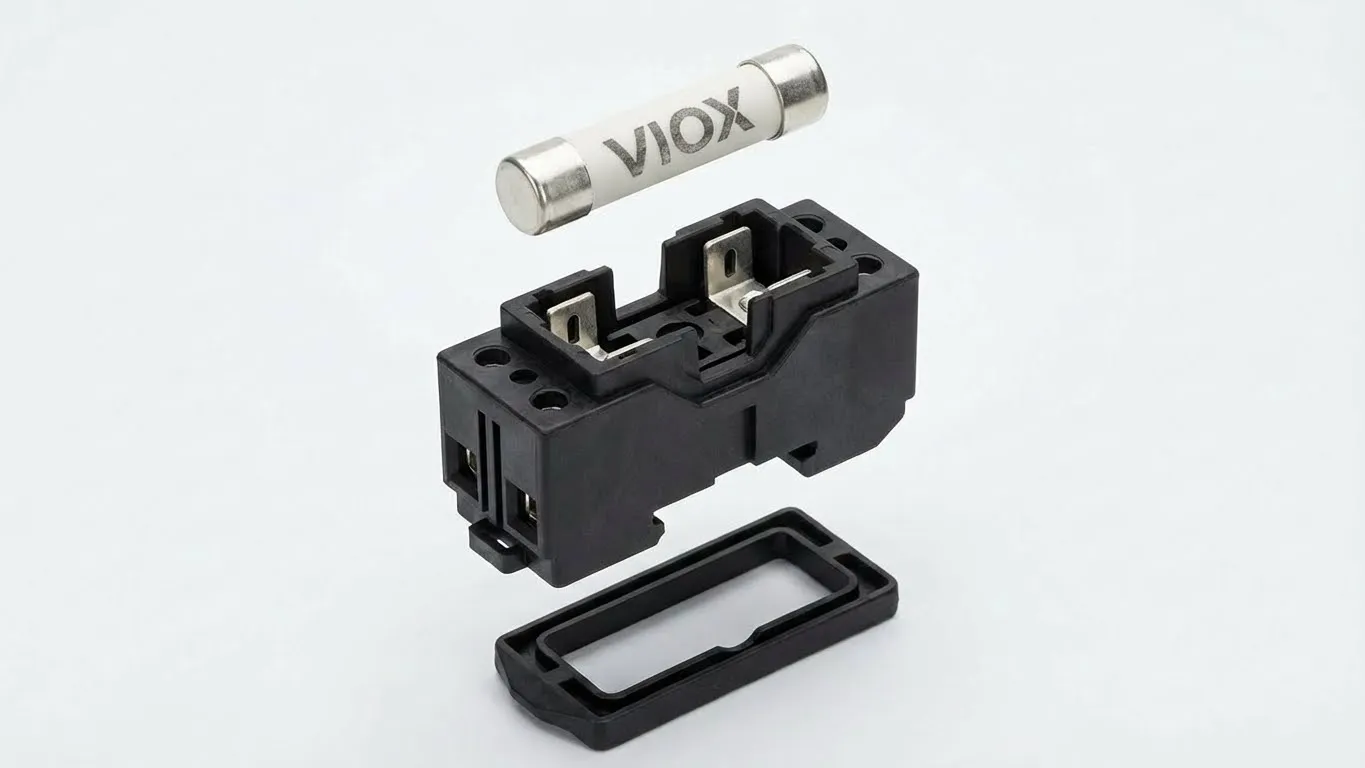
NH Fuses and Cylindrical Fuse Links: Practical Examples
NH (Knife-Blade) Fuses represent the most common industrial fuse system, standardized under IEC 60269-2. In this configuration:
- The white or cream-colored ceramic body with metal blade contacts = Fuse Link
- The black plastic housing with spring-loaded contacts = Fuse Base
- The optional red or black handle assembly = Fuse Carrier
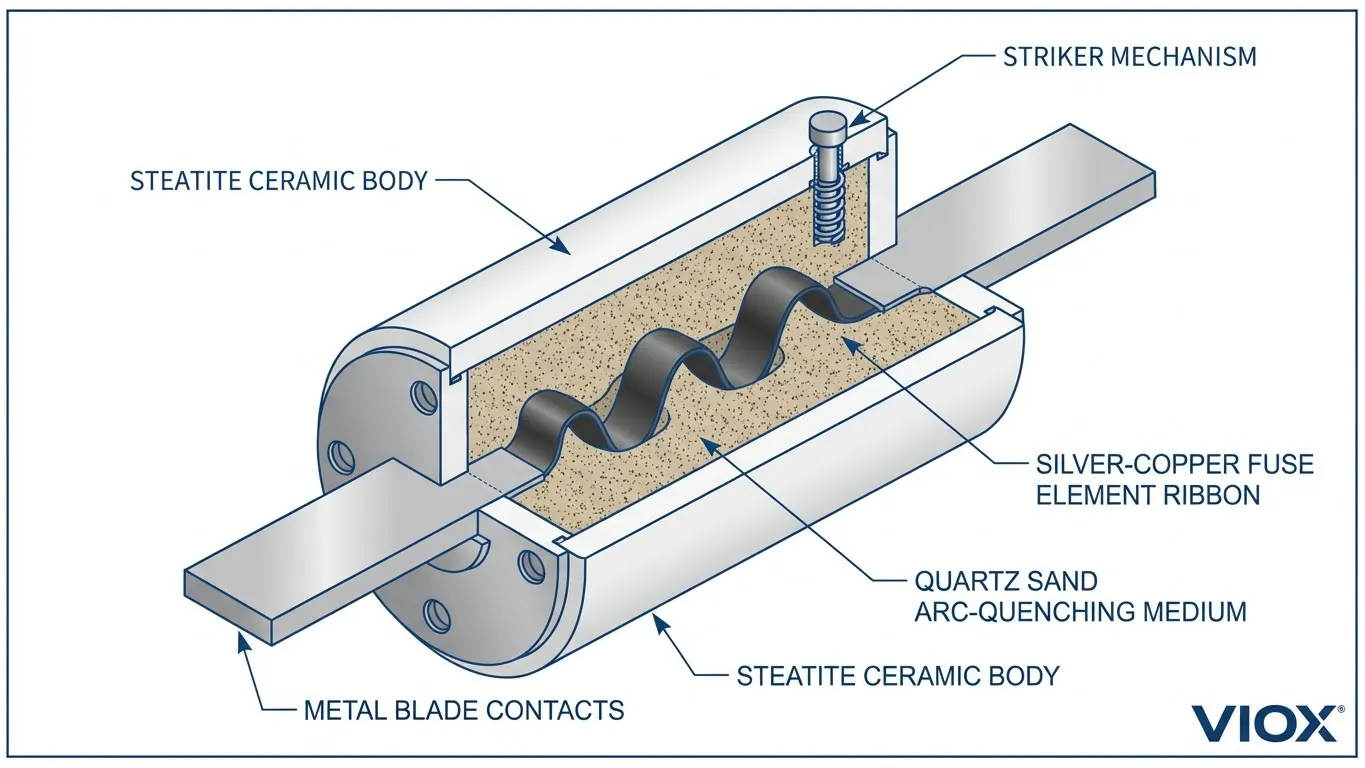
Cylindrical Fuses (such as 10x38mm or 22x58mm sizes) follow a similar logic:
- The ceramic tube with metal end caps = Fuse Link
- The clip-mount or holder assembly = Fuse Base
Without the base, the link cannot function. Without the link, the base is merely an open circuit. This interdependence creates the complete protective system.
Understanding gG and aM Fuse Classifications
IEC 60269 further categorizes fuse links by their time-current characteristics, indicated by a two-letter code. The two most common industrial classifications are:
gG Fuses (General Purpose, Full-Range Protection)
- “g” (lowercase) indicates protection across the entire overload range
- “G” (uppercase) signifies general-purpose applications
- Provides cable protection, transformer protection, and general circuit protection
- Typical operating characteristic: Blows within 2-5 seconds at 5× rated current, 0.1-0.2 seconds at 10× rated current
- Breaking capacity commonly exceeds 100 kA at 400/500V for NH systems
aM Fuses (Motor Protection, Partial-Range)
- “a” (lowercase) indicates partial-range protection (only against short circuits)
- “M” (uppercase) designates motor circuit applications
- Withstands motor starting inrush currents (typically 6-8× rated current for several seconds)
- Must be used with separate overload protection (motor protection relays or thermal overloads)
- Essential for preventing nuisance tripping during motor startup
| ဖျူးစ်အမျိုးအစား | Protection Range | ပုံမှန်လျှောက်လွှာ | Overload Response | Short-Circuit Response |
|---|---|---|---|---|
| gG | Full-range (overload + short-circuit) | Cable protection, transformer feeders, general circuits | Trips at 1.6× In (conventional fusing current) | Breaking capacity ≥100 kA |
| မနက် | Partial-range (short-circuit only) | Motor circuits, power conversion equipment | Withstands 6-8× In during startup | Breaking capacity ≥100 kA |
Time-Current Characteristics Comparison
| လက်ရှိအဆင့် | gG 20A Fuse Link | aM 20A Fuse Link |
|---|---|---|
| 1.6× In (32A) | ~1-2 hours | No trip (designed tolerance) |
| 3× In (60A) | ~30-60 seconds | ~5-10 minutes |
| 5× In (100A) | 2-5 seconds | 15-30 seconds |
| 10× In (200A) | 0.1-0.2 seconds | 0.2-0.5 seconds |
Procurement Best Practices for Industrial Fuses
Critical Rule: Never specify “fuse” without complete details in your Bill of Materials (BOM).
Incorrect specification:
- “100A fuse”
- “NH fuse for panel”
Correct specification:
- For replacement: “NH00 fuse link, 100A, gG, 500V AC” (IEC 60269-2)
- For new installation: “NH00 fuse base, 3-pole, with fuse links 100A gG” (complete system)
- For motor circuits: “NH1 fuse link, 63A, aM, 690V AC”
This precision eliminates procurement errors, reduces return shipping costs, and ensures compatibility with existing installations.
High-Voltage Utility Applications: Cutout Fuses and Pigtail Links
In the utility and high-voltage distribution sector, “fuse link” evokes an entirely different visual image. This context confusion frequently occurs when distributors handle both industrial and utility products.
Pole-Mounted Transformer Protection
Utility pole-mounted transformers—visible throughout distribution networks—require robust overcurrent protection against line faults, equipment failures, and overload conditions. The protective device mounted on these poles is a cutout fuse (also called a fuse cutout or dropout fuse), typically rated for 11-36 kV applications.
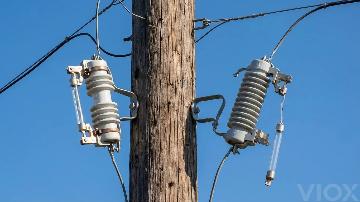
The “Pigtail” Fuse Link: A Different Design Philosophy
Unlike the ceramic cartridge fuse links used in industrial NH systems, utility fuse links resemble short cables:
- Physical appearance: Button head on one end, flexible stranded wire on the other (hence “pigtail”)
- တပ်ဆင်နည်း: Threaded through the fuse holder tube and secured under mechanical tension
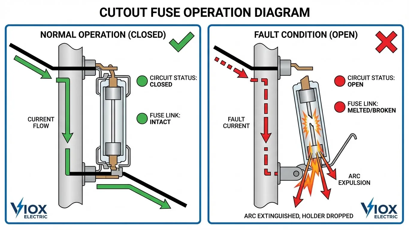
- Operation mechanism: When fault current melts the link, mechanical tension releases, causing the fuse holder to physically swing open (dropout)
- အမြင်အာရုံ: The dropped-out position provides immediate visual confirmation of operation
This dropout mechanism serves dual purposes: interrupting the fault current and providing utility crews with visible indication of the fault location from ground level.
K-Type vs. T-Type Fuse Links
Utility fuse links are categorized by speed characteristics according to IEEE C37.42-2016:
K-Type (Fast-Acting)
- Designed for line protection
- Rapid response to fault currents
- Suitable for applications requiring immediate interruption
- Typical applications: Distribution feeders, branch circuit protection
T-Type (Slow-Acting)
- Designed for transformer protection
- Tolerates magnetizing inrush currents during transformer energization
- Prevents nuisance operations during switching transients
- Typical applications: Distribution transformers, capacitor banks
| လက္ခဏာ | Utility Cutout Fuse | Industrial NH Fuse |
|---|---|---|
| ဗို့ပးခ်က္ | 11-36 kV | 400-1000V AC |
| Fuse Link Form | Flexible pigtail wire | Rigid ceramic cartridge |
| လည်ပတ်မှု ယန္တရား | Mechanical dropout | Fixed position (requires manual removal) |
| အမြင်အာရုံ ညွှန်ပြခြင်း။ | Self-evident (dropped open) | Indicator pin or window |
| ရိုးရိုးကုန်ကျစရိတ် | $5-15 (link only) | $8-50 (လင့်ခ်သာ) |
| တပ်ဆင်မှုကုန်ကျစရိတ် အပြီးအစီး | $200-800 | $150-400 |
မော်တော်ယာဉ် ဖျူးစပ်ဆက်များ- ဝှက်ထားသော ကာကွယ်ရေး အစိတ်အပိုင်း
မော်တော်ယာဉ် လျှပ်စစ်စနစ်များတွင် အခေါ်အဝေါ်များသည် ပြန်လည်ပြောင်းလဲပါသည်။ လူအများစုသည် ယာဉ်၏ ဖျူးဘောက်စ်အတွင်းရှိ ဘလိတ်ဖျူးများ (ATO/ATC အမျိုးအစားများ) ကို မှတ်မိကြသော်လည်း၊, ဖျူးစပ်ဆက်များ ၎င်းတို့၏ လှည့်စားတတ်သော ပုံပန်းသဏ္ဌာန်ကြောင့် ပို၍အန္တရာယ်များသော အစိတ်အပိုင်းကို ကိုယ်စားပြုသည်။.
မော်တော်ယာဉ် ဖျူးစပ်ဆက် ဆိုသည်မှာ အဘယ်နည်း။
မော်တော်ယာဉ် အသုံးချမှုများတွင် ဖျူးစပ်ဆက်သည် ဗို့အားနိမ့် ကေဘယ်လ်၏ အပိုင်းတိုတစ်ခုဖြစ်ပြီး ပုံမှန်အားဖြင့် ဘက်ထရီ အပေါင်း တာမီနယ် သို့မဟုတ် အော်လ်တာနေးတာအနီးတွင် တည်ရှိသည်။ ဤကာကွယ်ရေးကိရိယာသည် စံမော်တော်ယာဉ်ဝါယာကြိုးနှင့် အလွန်နီးစပ်စွာ တူညီသောကြောင့် ခွဲခြားသတ်မှတ်ရာတွင် စိန်ခေါ်မှုများ ဖြစ်ပေါ်စေသည်။.
အရေးကြီးသော သတ်မှတ်ချက်များ:
- ဝါယာကြိုး ဂေ့ခ်ျ အရွယ်အစား: ကာကွယ်ပေးသည့် ဆားကစ်ထက် ပုံမှန်အားဖြင့် အမေရိကန်ဝါယာဂေ့ခ်ျ (AWG) အရွယ်အစား လေးခု သေးငယ်သည်။
- လျှပ်ကာ အမျိုးအစား: အရည်ပျော်သောအခါ ပူဖောင်းထခြင်း သို့မဟုတ် မီးခိုးရောင်ပြောင်းသွားခြင်း သို့သော် မီးမစွဲလောင်သော အထူးမီးမလောင်နိုင်သော လျှပ်ကာ
- အရှည်: ပုံမှန်အားဖြင့် ၆-၉ လက်မ
- တည်နေရာ: လျှပ်စီးကြောင်းအားမြင့်သော အရင်းအမြစ်များ (ဘက်ထရီ၊ အော်လ်တာနေးတာ) နှင့် ဖြန့်ဖြူးသည့်နေရာများအကြား
ဥပမာ: 10 AWG ဝါယာကြိုးကို အသုံးပြုထားသော ဆားကစ်တစ်ခုအား 14 AWG ဖျူးစပ်ဆက်ဖြင့် ကာကွယ်ပေးမည်ဖြစ်သည်။.
ဘေးကင်းရေး အန္တရာယ်- သင့်လျော်သော ခွဲခြားသတ်မှတ်မှုသည် အဘယ်ကြောင့် အရေးကြီးသနည်း။
ဖျူးစပ်ဆက်များ၏ အဓိကအန္တရာယ်မှာ ၎င်းတို့၏ ဝါယာကြိုးနှင့်တူသော ပုံပန်းသဏ္ဌာန်မှ ဖြစ်ပေါ်လာခြင်းဖြစ်သည်။ အတွေ့အကြုံမရှိသော ٹیکنیشینများသည် ပျက်စီးနေသော ဝါယာကြိုးအတွက် လွင့်ထွက်သွားသော ဖျူးစပ်ဆက်ကို မကြာခဏ မှားယွင်းစွာ ထင်မြင်ကြပြီး စံမော်တော်ယာဉ်ဝါယာကြိုးကို ဆက်ခြင်းဖြင့် “ပြုပြင်” ကြသည်။ ဤအစားထိုးမှုသည် လျှပ်စီးကြောင်းပိုလျှံမှု ကာကွယ်ရေးကို ဖယ်ရှားပေးပြီး ပြင်းထန်သော မီးအန္တရာယ်ကို ဖန်တီးပေးသည်။.
မသင့်လျော်သော အစားထိုးမှု၏ အကျိုးဆက်များ:
- နောက်လျှပ်စစ်ဆားကစ်တို ဖြစ်ပေါ်မှုသည် ကာကွယ်ရေး အဟန့်အတားကို မဖြစ်ပေါ်စေပါ။
- စံဝါယာကြိုးသည် လျှပ်ကာအရည်ပျော်သည်အထိ ချို့ယွင်းချက် လျှပ်စီးကြောင်းကို သယ်ဆောင်သည်။
- ဝါယာကြိုးကြိုးမီးလောင်မှုနှင့် ယာဉ်ပျက်စီးမှု ဖြစ်နိုင်ခြေ
- ဆက်တိုက်ဖြစ်ပေါ်နေသော ဆားကစ်တိုကြောင့် ဘက်ထရီပေါက်ကွဲနိုင်ခြေ
သင့်လျော်သော အစားထိုးမှု လုပ်ထုံးလုပ်နည်း:
- ဖျူးစပ်ဆက်များကို အမြဲတမ်း OEM မှ သတ်မှတ်ထားသော သို့မဟုတ် တူညီသော အဆင့်သတ်မှတ်ထားသော အစိတ်အပိုင်းများနှင့် အစားထိုးပါ။
- မည်သည့်ဂေ့ခ်ျ၏ စံဝါယာကြိုးနှင့်မျှ ဘယ်တော့မှ အစားမထိုးပါနှင့်။
- အစားထိုးဝါယာကြိုးတွင် အပူချိန်မြင့်မားသော၊ မီးလောင်မှုကို နှေးကွေးစေသော လျှပ်ကာပါဝင်ကြောင်း အတည်ပြုပါ။
- ဝါယာကြိုးဂေ့ခ်ျသည် မှန်ကန်သောအရွယ်အစား (ကာကွယ်ထားသော ဆားကစ်ထက် ဂေ့ခ်ျလေးခု သေးငယ်သည်) ဖြစ်ကြောင်း သေချာပါစေ။
ဖျူးစပ်ဆက်နှင့် စံဘလိတ်ဖျူး နှိုင်းယှဉ်ခြင်း
| အင်္ဂါ | ဖျူးစပ်ဆက် | ဘလိတ်ဖျူး (ATO/ATC) |
|---|---|---|
| ရုပ်ပိုင်းဆိုင်ရာ ပုံစံ | ဝါယာကြိုးအပိုင်း | သတ္တု တာမီနယ်များနှင့် ပလတ်စတစ်ကိုယ်ထည် |
| တည်နေရာ | ဘက်ထရီအနီးရှိ အင်ဂျင်ခန်းအတွင်း | ဖျူးဘောင်၊ အတွင်းပိုင်း |
| ခွဲခြားသတ်မှတ်ခြင်း | ခက်ခဲသည် (ဝါယာကြိုးနှင့်တူသည်) | လွယ်ကူသည် (အရောင်ကုဒ်ဖြင့်မှတ်သားထားသည်၊ အဆင့်သတ်မှတ်ထားသော အမှတ်အသားများ) |
| ကာကွယ်မှုအဆင့် | လျှပ်စီးကြောင်းအားမြင့်သော ဆားကစ်များ (60-150A) | အလယ်အလတ်မှ အလယ်အလတ် ဆားကစ်များ (ပုံမှန်အားဖြင့် 3-30A) |
| အစားထိုးရန် ခက်ခဲခြင်း | အလယ်အလတ် (ဂဟေဆက်ခြင်း/ဖိခြင်း လိုအပ်သည်) | ရိုးရှင်းသည် (ပလပ်ထိုးခြင်း) |
| အမြင်အာရုံ ညွှန်ပြခြင်း။ | မရှိပါ (အရည်ပျော်သွားသော ဝါယာကြိုး) | ကျိုးပဲ့နေသော ဖိုင်လာမန်ကို မြင်နိုင်သည်။ |
ပြည့်စုံသော နှိုင်းယှဉ်ချက်- အကြောင်းအရာ သုံးခုလုံး
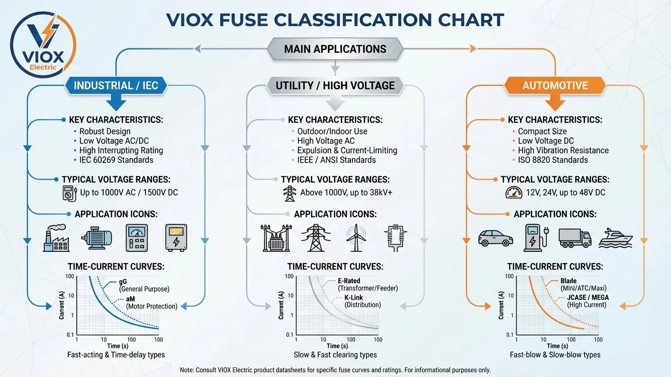
| အသုံးချမှုအခြေအနေ | စနစ်အမည် | အစားထိုးနိုင်သော အစိတ်အပိုင်း | အဓိကအသုံးပြုမှု | ဗို့အားအကွာအဝေး | ပုံမှန် Breaking Capacity |
|---|---|---|---|---|---|
| စက်မှု (IEC) | NH ဖျူးစနစ် | NH ဖျူးလင့်ခ် (ကြွေပြွန်) | ဘောင်ကာကွယ်ရေး၊ မော်တာဆားကစ်များ၊ ကေဘယ်လ်ကာကွယ်ရေး | 400-1000V AC | 100-120 kA |
| စက်မှု (IEC) | ဆလင်ဒါပုံ ဖျူး | ဆလင်ဒါပုံ ဖျူးလင့်ခ် | ထိန်းချုပ်ရေးဆားကစ်များ၊ အီလက်ထရွန်းနစ်ပစ္စည်းများ | 250-690V AC | 50-100 kA |
| အသုံးအဆောင် (HV) | ကပ်အောက် ဖျူး | ပစ်ဂ်တေးလ် ဖျူးလင့်ခ် | ထရန်စဖော်မာ ကာကွယ်ရေး၊ လိုင်းပိုင်းခွဲခြင်း | 11-36 kV | 6-10 kA (ထုတ်ပစ်ခြင်း) |
| မော်တော်ကား | ဖျူးစပ်ဆက်ပစ္စည်း | ဖျူးစပ်ဆက်ဝါယာကြိုး | ဘက်ထရီ/အော်တာနေးတာ ကာကွယ်မှု | ၁၂-၄၈V ရွက် | 500-1000A |
| မော်တော်ကား | ဓါးသွားဖျူးကိုင် | ဓါးသွားဖျူး | ဆက်စပ်ဆားကစ်များ | ၁၂-၄၈V ရွက် | အများဆုံး 60-100A |
IEC ဖျူးအရွယ်အစား သတ်မှတ်ချက်များ
| NH အရွယ်အစား | အဆင့်သတ်မှတ်ထားသော လက်ရှိအဆင့် | ရုပ်ပိုင်းဆိုင်ရာ အတိုင်းအတာများ (L × W) | ပံုမွန္အသံုးခ်ျခင္း | 500V တွင် ဖြတ်တောက်နိုင်စွမ်း |
|---|---|---|---|---|
| NH000 | 2-160A | 185mm × 65mm | ထိန်းချုပ်ဘောင်များ၊ မော်တာအသေးများ | 120 kA |
| NH00 | 2-160A | 140mm × 50mm | ဖြန့်ဖြူးရေးဘုတ်များ၊ မော်တာအလတ်စားများ | 120 kA |
| NH0 | 4-100A | 95mm × 45mm | ခွဲဖြန့်ဖြူးခြင်း၊ မော်တာအသေးစားများ | 120 kA |
| NH1 | 10-160A | 115mm × 54mm | အဓိက ဖြန့်ဖြူးခြင်း၊ မော်တာထိန်းချုပ်ရေးစင်တာများ | 120 kA |
| NH2 | 125-250A | 150mm × 69mm | စက်မှုလုပ်ငန်းသုံး လျှပ်စစ်ဓာတ်အားလိုင်းများ၊ မော်တာအကြီးစားများ | 120 kA |
| NH3 | 200-630A | 215mm × 100mm | အဓိက ခလုတ်ဂီယာ၊ ထရန်စဖော်မာ ဒုတိယအလိပ်များ | 120 kA |
| NH4 | 500-1250A | 330mm × 155mm | ဝန်ဆောင်မှုဝင်ပေါက်၊ စက်မှုဝန်အားကြီးများ | 80-100 kA |
ကျွမ်းကျင်သော ဝယ်ယူမှု လမ်းညွှန်ချက်များ
စက်မှုလုပ်ငန်းအလိုက် အကောင်းဆုံး မှာယူမှု အလေ့အကျင့်များ
စက်မှု/ဘောင် တည်ဆောက်ခြင်း အသုံးချမှုများအတွက်:
- တပ်ဆင်မှုအသစ်များ: စနစ်အစုံကို သတ်မှတ်ပါ
- “NH1 ဖျူးခလုတ်ဖြုတ်ဆက်ကိရိယာ၊ 3-ဝင်ရိုး၊ 160A၊ gG ဖျူးစပ်ဆက်ပစ္စည်းများ အပါအဝင်”
- ခလုတ်ဖြုတ်ဆက်ကိရိယာ လုပ်ဆောင်ချက် လိုအပ်ခြင်း ရှိမရှိ အမြဲဖော်ပြပါ
- ပြုပြင်ထိန်းသိမ်းခြင်း/အစားထိုးခြင်း: စပ်ဆက်ပစ္စည်းများကိုသာ သတ်မှတ်ပါ
- “NH00 ဖျူးစပ်ဆက်ပစ္စည်း၊ 63A၊ gG၊ 500V AC၊ IEC 60269-2”
- လိုက်ဖက်ညီမှု အရေးကြီးပါက လက်ရှိ အခြေခံထုတ်လုပ်သူကို ထည့်သွင်းပါ
- Motor circuits: aM အမျိုးအစားခွဲခြားမှုကို အမြဲသတ်မှတ်ပါ
- “NH2 ဖျူးစပ်ဆက်ပစ္စည်း၊ 200A၊ aM၊ 690V AC” (gG မဟုတ်ပါ)
- မော်တာကာကွယ်ရေး ရီလေး ဆက်တင်များနှင့် ညှိနှိုင်းပါ
အသုံးအဆောင်/ဗို့အားမြင့် အသုံးချမှုများအတွက်:
- စုံလင်သော စပ်ဆက်ပစ္စည်းများ:
- “15 kV ဖြတ်တောက်ဖျူး စပ်ဆက်ပစ္စည်း၊ ပိုလီမာ လျှပ်ကာ၊ 100A အဆင့်သတ်မှတ်”
- အစားထိုး စပ်ဆက်ပစ္စည်းများ:
- “K-အမျိုးအစား ဖျူးစပ်ဆက်ပစ္စည်း၊ 15 kV၊ 40A” သို့မဟုတ် “T-အမျိုးအစား ဖျူးစပ်ဆက်ပစ္စည်း၊ 15 kV၊ 65A”
- အသုံးချမှု (လိုင်းနှင့် ထရန်စဖော်မာ) ပေါ်မူတည်၍ K နှင့် T အမျိုးအစားကို စစ်ဆေးပါ
မော်တော်ယာဉ်/ယာဉ်အုပ်စု အသုံးချမှုများအတွက်:
- ဖျူးစပ်ဆက်ပစ္စည်းများအတွက် “ဝါယာကြိုး” ဟု ဘယ်တော့မှ မသတ်မှတ်ပါနှင့်
- “ဖျူးစပ်ဆက်ပစ္စည်း၊ 12V၊ 14 AWG၊ 9-လက်မ အရှည်၊ အပူချိန်မြင့် လျှပ်ကာ”
- ရရှိနိုင်ပါက OEM အစိတ်အပိုင်း နံပါတ်များကို အမြဲကိုးကားပါ
Common Procurement Mistakes to Avoid
| အမှား | Consequence | Correct Approach |
|---|---|---|
| Ordering “100A fuse” without specification | Receive complete assembly when only link needed (cost overrun) | Specify “NH00 fuse link, 100A, gG” |
| Using gG fuses in motor circuits | Nuisance tripping during motor startup | Specify aM fuses for motor circuits |
| Ordering fuse links without verifying base compatibility | Dimensional mismatch, unusable parts | Reference existing fuse system type (NH, BS88, etc.) |
| Replacing fusible links with standard wire | Fire hazard, loss of protection | Use only OEM or rated fusible link replacements |
| Mixing voltage ratings | Safety hazard, code violations | Always match or exceed system voltage rating |
VIOX Electric Product Recommendations
At VIOX Electric, we manufacture comprehensive fuse solutions for industrial applications:
- NH Fuse Links: Available in sizes NH000 through NH4, both gG and aM characteristics, rated to 120 kA breaking capacity
- Fuse Bases and Carriers: Designed for NH knife-blade systems with easy maintenance access
- Fuse Switch Disconnectors: Combined protection and isolation in a single assembly
- Cylindrical Fuse Links: 10x38mm, 14x51mm, and 22x58mm sizes for control circuit applications
All VIOX fuse products comply with IEC 60269-1:2024 and IEC 60269-2:2024, ensuring global compatibility and reliable performance in demanding industrial environments.
Technical Standards Reference
Understanding the governing standards ensures compliance and proper specification:
IEC 60269 Series (Low-Voltage Fuses)
IEC 60269-1:2024 (General Requirements, Edition 5.0)
- Establishes baseline requirements for all fuse-links rated ≥6 kA breaking capacity
- Defines terminology: fuse, fuse-link, fuse-base, fuse-carrier
- Specifies testing protocols for time-current characteristics and breaking capacity
- Applicable to AC circuits up to 1000V
IEC 60269-2:2024 (Industrial Fuses, Consolidated Edition)
- Supplementary requirements for fuses used by authorized persons only
- Covers standardized fuse systems A through K
- Includes NH knife-blade fuses (most common industrial type)
- Defines gG and aM characteristic requirements
- Specifies mechanical dimensions for interchangeability
IEC 60269-6:2010 (Photovoltaic Fuses)
- Supplementary requirements for DC fuses in solar applications
- Rated up to 1500V DC
- Addresses unique DC arc interruption challenges
IEEE Standards (Utility Applications)
IEEE C37.42-2016 (Distribution Fuses and Accessories)
- Performance requirements for high-voltage expulsion-type fuses
- Covers fuse cutouts, fuse disconnecting switches
- Specifies interrupting ratings up to 10 kA symmetrical
- Defines K-type and T-type characteristics
IEEE C37.41-2024 (Current-Limiting Fuses)
- Design tests for high-voltage current-limiting fuses
- Applicable to utility transformer protection
- Covers E-rated fuses for expulsion operation coordination
These standards ensure that fuse products from different manufacturers with identical ratings will perform consistently, enabling safe substitution and reliable system protection.
Conclusion: Precision in Terminology Equals Cost Savings
The distinction between “fuse” (complete protective system) and “fuse link” (replaceable element) transcends mere semantics—it represents a fundamental understanding that directly impacts procurement costs, system safety, and operational reliability.
အဓိက သင်ခန်းစာများ:
- Industrial context: “Fuse” = base + carrier + link; “Fuse link” = ceramic cartridge with contacts
- Utility context: “Cutout fuse” = complete assembly; “Fuse link” = pigtail wire element
- Automotive context: “Fusible link” = special wire segment; never replace with standard wire
- Procurement rule: Always specify complete technical details (size, rating, type, voltage, standard)
- Safety principle: Use only components designed for the specific application—no substitutions
At VIOX Electric, we understand that B2B customers require more than products—they need technical expertise, precise specifications, and reliable partnerships. Our industrial fuse systems comply with IEC 60269 standards, providing the breaking capacity, selectivity, and durability demanded by modern electrical installations.
Whether you’re specifying a new panel build, maintaining existing equipment, or sourcing replacement components, understanding the fuse vs. fuse link distinction ensures you order correctly the first time—eliminating costly delays, returns, and safety compromises.
Ready to specify the right protection for your application? ဆက်သွယ်ရန် VIOX လျှပ်စစ်‘s technical team for application-specific recommendations, complete technical data sheets, and competitive quotations on industrial fuse systems engineered for reliability and performance.
