
တိုက်ရိုက်အဖြေ
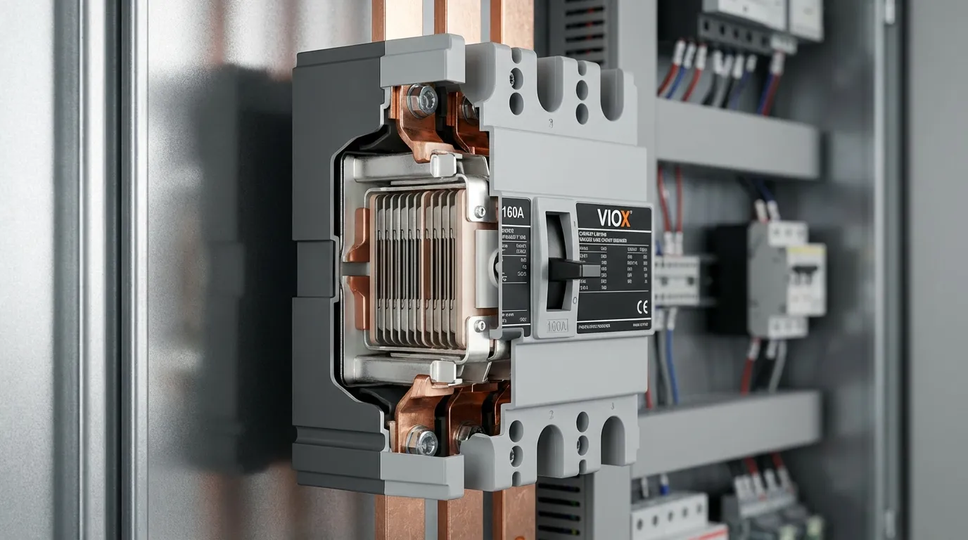
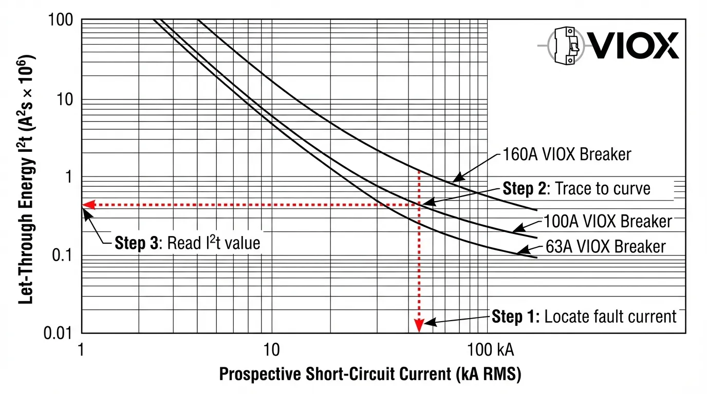
The I²t (permissible energy) curve of a circuit breaker shows the thermal energy that passes through during fault interruption. Reading this curve is straightforward: locate your prospective short-circuit current on the X-axis, trace upward to intersect the breaker’s curve, then read the corresponding I²t value on the Y-axis. This value must be less than your conductor’s thermal withstand capacity (K²S²) to ensure safe operation. For example, a 160A current-limiting breaker interrupting a 100kA fault typically limits I²t to approximately 0.48×10⁶ A²s, preventing cable and busbar thermal damage that would otherwise occur within milliseconds.
What Is I²t and Why It Matters for Electrical Safety
When a short-circuit fault occurs in an electrical system, the massive current surge generates intense heat through the I²R effect. The total thermal energy absorbed by conductors depends on both the magnitude of current and the duration before the protective device clears the fault. This relationship is expressed as I²t—the integral of current squared over time, measured in ampere-squared seconds (A²s).
Current-limiting circuit breakers possess a critical advantage: they dramatically reduce both the peak current and clearing time during faults. According to IEC 60947-1 standards, the permissible energy curve (also called let-through energy curve) quantifies exactly how much thermal stress the breaker allows downstream conductors to experience. Understanding and applying these curves prevents conductor overheating, insulation damage, and potential fire hazards in electrical installations.
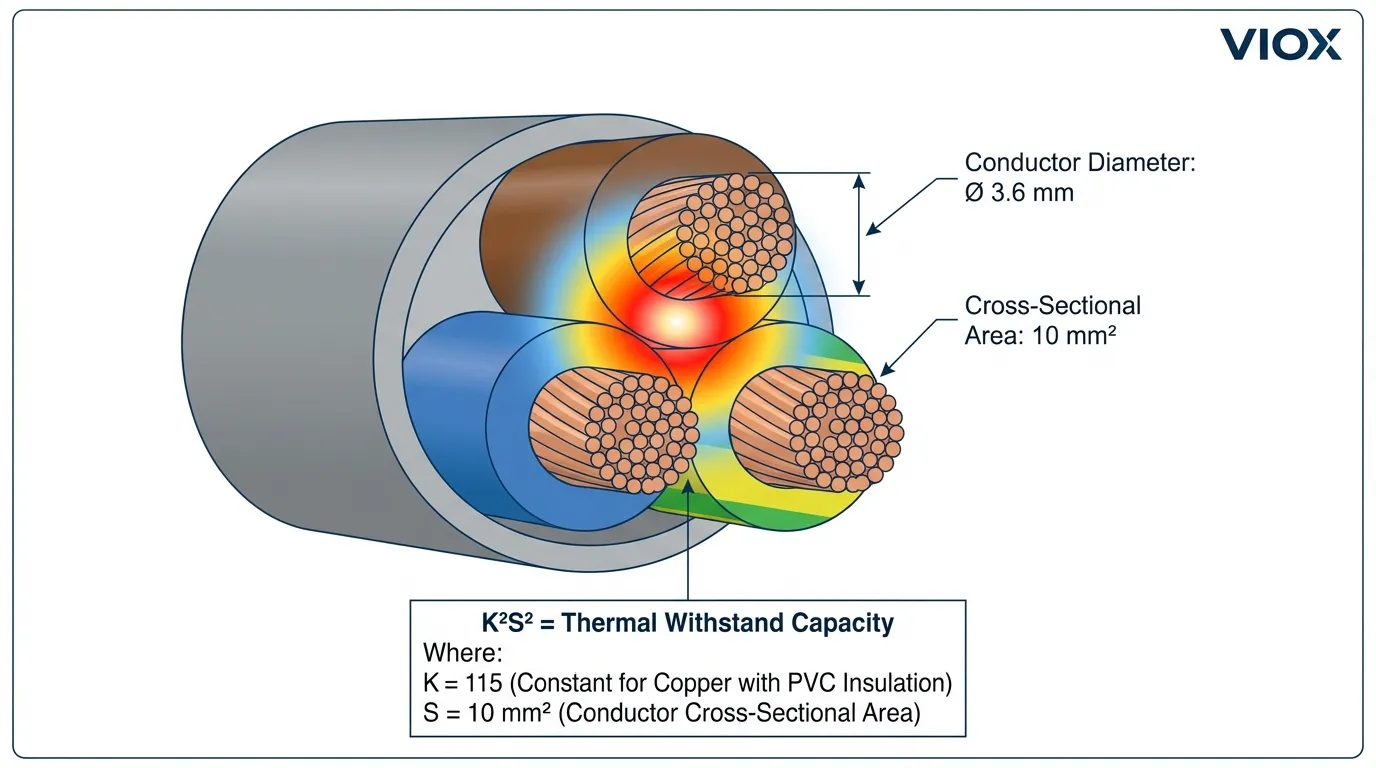
Modern electrical systems increasingly rely on smaller conductor cross-sections for cost efficiency, making thermal protection more critical than ever. A standard 10mm² PVC cable can withstand only 1.32×10⁶ A²s before insulation failure, yet a non-current-limiting breaker might allow several times this energy to pass during a high-magnitude fault.
How Current-Limiting Breakers Reduce Thermal Stress
The Physics of Current Limitation
Current-limiting circuit breakers employ rapid contact separation combined with specialized arc-quenching chambers. When fault current begins to flow, the breaker’s contacts open within 2-5 milliseconds—often before the fault current reaches its first prospective peak. The arc voltage created during interruption opposes the system voltage, effectively inserting impedance into the fault path and “chopping” the current waveform.
This current-limiting action produces two measurable benefits captured in manufacturer data sheets: the peak let-through current (Ip) and the let-through energy (I²t). While peak current determines mechanical stress on busbars, the I²t value governs thermal stress on all conductors in the fault path.
Comparing Limited vs. Unlimited Fault Energy
Consider a 100kA prospective short-circuit on a system protected by different devices:
| ကာကွယ်ရေးကိရိယာ | ရှင်းလင်းချိန် | Peak Current | I²t တန်ဖိုး | Temperature Rise (100×10mm busbar) |
|---|---|---|---|---|
| အကာအကွယ်မရှိ။ | မရှိ | 141 kA peak | ကပ်ဘေး | Vaporization |
| Standard MCCB (short-time delay) | 500 ms | 100 kA RMS | ~5×10⁹ A²s | >500°C (failure) |
| Current-limiting MCCB (160A) | 8 ms | 42 kA peak | 0.48×10⁶ A²s | 71°C (safe) |
| Current-limiting fuse (160A) | 4 ms | 38 kA peak | 0.35×10⁶ A²s | 70.5°C (safe) |
This comparison demonstrates why current-limiting protection is essential for modern installations with high available fault currents. The reduction in I²t by three to four orders of magnitude transforms a catastrophic thermal event into a manageable temperature excursion.
Reading I²t Curves: A Step-by-Step Guide
Understanding the Curve Format
Manufacturer datasheets present I²t curves on logarithmic scales with prospective short-circuit current (X-axis) plotted against let-through energy (Y-axis). Multiple curves typically appear on one chart, representing different breaker frame sizes or ratings within a product family.
Five Steps to Apply I²t Curves
Step 1: Calculate Prospective Short-Circuit Current
Determine the maximum available fault current at the point of installation using system impedance calculations per IEC 60909 or equivalent standards. This represents the current that would flow if the breaker were replaced by a solid conductor.
Step 2: Locate Current on X-Axis
Find your calculated prospective current value on the horizontal axis of the I²t curve chart. If your value falls between gridlines, interpolate logarithmically or use the next higher value for conservative results.
Step 3: Trace Vertically to Breaker Curve
Draw an imaginary vertical line upward from your current value until it intersects the curve corresponding to your specific breaker rating. Different ampere ratings have distinct curves—ensure you’re reading the correct one.
Step 4: Read I²t Value on Y-Axis
From the intersection point, trace horizontally to the left Y-axis to read the let-through energy value. Note the units carefully—values are typically expressed as A²s × 10⁶ or similar scientific notation.
Step 5: Compare with Conductor Withstand
Verify that the breaker’s I²t value is less than the conductor’s maximum thermal withstand capacity using the formula K²S² (explained in the next section).
Common Reading Mistakes to Avoid
Engineers frequently make three critical errors when interpreting I²t curves:
Confusing RMS and Peak Values: The X-axis shows prospective RMS symmetrical current, not peak asymmetrical current. Using peak values will position you incorrectly on the curve, typically resulting in overly optimistic I²t readings.
Mismatching Breaker Ratings: Product families often display multiple curves on one chart. Always verify you’re reading the curve that matches your installed breaker’s ampere rating and breaking capacity (e.g., a “C” curve 10kA breaker differs from an “N” curve 36kA breaker of the same amperage).
Ignoring Logarithmic Scaling: Both axes use logarithmic scales. A small visual distance on the chart represents a large numerical change. Always read values carefully from the axis labels rather than estimating visually.
Calculating Conductor Thermal Withstand Capacity
The K²S² Formula Explained
Every conductor has a maximum thermal energy it can absorb before insulation damage occurs. This limit is expressed by the adiabatic equation:
I²t ≤ K²S²
Where:
- I²t = Let-through energy from the protective device (A²s)
- K = Material and insulation constant (A·s½/mm²)
- ၎ = Conductor cross-sectional area (mm²)
The constant K accounts for conductor material (copper or aluminum), insulation type (PVC, XLPE, EPR), initial temperature (typically 70°C for continuous operation), and final permissible temperature (160°C for PVC, 250°C for XLPE). IEC 60364-5-54 provides standardized K values.
သာမန်လျှပ်ကူးပစ္စည်းများအတွက် စံ K တန်ဖိုးများ
| စပယ်ယာပစ္စည်း | လျှပ်ကာအမျိုးအစား | မူလအပူချိန် | နောက်ဆုံးအပူချိန် | K တန်ဖိုး (A·s½/mm²) |
|---|---|---|---|---|
| ကြေးနီ | PVC | 70°C | 160°C | 115 |
| ကြေးနီ | XLPE/EPR | 90°C | 250°C | 143 |
| ကြေးနီ | သတ္တု (PVC) | 70°C | 160°C | 115 |
| အလူမီနီယံ | PVC | 70°C | 160°C | 76 |
| အလူမီနီယံ | XLPE/EPR | 90°C | 250°C | 94 |
လက်တွေ့တွက်ချက်မှုဥပမာ
Scenario: VIOX NSX160F breaker (36kA ဖြတ်တောက်နိုင်စွမ်း) သည် ဖြစ်နိုင်ချေရှိသော ချို့ယွင်းလျှပ်စီးကြောင်း 25kA ရှိသော PVC လျှပ်ကာပါရှိသော 10mm² ကြေးနီလျှပ်ကူးပစ္စည်းကို လုံလောက်စွာကာကွယ်နိုင်ခြင်းရှိမရှိ စစ်ဆေးပါ။.
အဆင့် ၁: ထုတ်လုပ်သူမျဉ်းကွေးမှ breaker I²t ကိုရှာဖွေပါ
- ဖြစ်နိုင်ချေရှိသော လျှပ်စီးကြောင်း: 25 kA
- VIOX NSX160F ဒေတာစာရွက်မျဉ်းကွေးမှ: I²t = 6×10⁵ A²s
အဆင့် ၂: ကေဘယ်လ်၏ အပူခံနိုင်ရည်ကို တွက်ချက်ပါ
- K = 115 (အထက်ပါဇယားမှ ကြေးနီ PVC)
- S = 10 mm²
- K²S² = 115² × 10² = 1.32×10⁶ A²s
အဆင့် ၃: ကာကွယ်မှုကို စစ်ဆေးပါ
- Breaker I²t (6×10⁵) < Cable K²S² (1.32×10⁶) ✓
- ဘေးကင်းလုံခြုံမှုအနားသတ်: (1.32 – 0.6) / 1.32 = 54.51%
နိဂုံး: ကေဘယ်လ်ကို သိသာထင်ရှားသော ဘေးကင်းလုံခြုံမှုအနားသတ်ဖြင့် လုံလောက်စွာကာကွယ်ထားသည်။.
I²t ကို အသုံးပြု၍ Busbar ၏ အပူပိုင်းဆိုင်ရာ အတည်ပြုချက်
Busbar များသည် အဘယ်ကြောင့် အထူးထည့်သွင်းစဉ်းစားရန် လိုအပ်သနည်း
ဖြန့်ဖြူးရေးအကန့်များနှင့် ခလုတ်ဂီယာရှိ Busbar များသည် ချို့ယွင်းမှုများအတွင်း ကေဘယ်လ်များနှင့် တူညီသော အပူပိုင်းဆိုင်ရာ ဖိအားကို ရင်ဆိုင်ရသော်လည်း ၎င်းတို့၏ အတည်ပြုခြင်းလုပ်ငန်းစဉ်သည် ဂျီသြမေတြီနှင့် တပ်ဆင်မှုအခြေအနေများကြောင့် အနည်းငယ်ကွဲပြားပါသည်။ ကြေးနီ သို့မဟုတ် အလူမီနီယမ်ဘားများသည် အပူစီးကူးနိုင်စွမ်းကောင်းမွန်သော်လည်း အလုံပိတ်အကန့်များတွင် ၎င်းတို့၏ ကျစ်လစ်သိပ်သည်းသော အစီအစဉ်သည် ခဏတာ ချို့ယွင်းမှုကြာချိန်အတွင်း အပူလွန်ကဲမှုကို ကန့်သတ်ထားသည်။.
တူညီသော I²t မူသည် အကျုံးဝင်သော်လည်း အင်ဂျင်နီယာများသည် AC အရေပြားအကျိုးသက်ရောက်မှုအချက် (Kf) နှင့် တိကျသော လျှပ်ကူးပစ္စည်းအတိုင်းအတာများကို ထည့်သွင်းစဉ်းစားရမည်ဖြစ်သည်။ စတုဂံပုံ ကြေးနီ busbar များအတွက် အပူခံနိုင်ရည် တွက်ချက်မှုမှာ-
θk = θ0 + (I²t × Kf × ρ0) / (A² × c × γ × (1 + α0 × θ0))
Where:
- θk = နောက်ဆုံးအပူချိန် (°C)
- θ0 = မူလအပူချိန် (ပုံမှန်အားဖြင့် စဉ်ဆက်မပြတ်လည်ပတ်မှုအတွက် 70°C)
- I²t = Let-through စွမ်းအင် (A²s)
- Kf = AC ထပ်ဆောင်းဆုံးရှုံးမှုကိန်း (ပုံမှန်အားဖြင့် ကြိမ်နှုန်းနှင့် ဘားအတိုင်းအတာပေါ်မူတည်၍ 1.0-1.5)
- ρ0 = 0°C တွင် ခုခံမှု (ကြေးနီအတွက် 1.65×10⁻⁸ Ω·m)
- A = ဖြတ်ပိုင်းဧရိယာ (m²)
- c = သီးခြားအပူစွမ်းရည် (ကြေးနီအတွက် 395 J/(kg·K))
- γ = သိပ်သည်းဆ (ကြေးနီအတွက် 8900 kg/m³)
- α0 = အပူချိန်ကိန်းဂဏန်း (ကြေးနီအတွက် 1/235 K⁻¹)
လုပ်ဆောင်ပြီးသော ဥပမာ- Busbar အပူချိန်မြင့်တက်ခြင်း
ပေးထားသည်။: 100×10mm ကြေးနီ busbar၊ မူလအပူချိန် 70°C၊ 160A လက်ရှိကန့်သတ် breaker ဖြင့် ကာကွယ်ထားပြီး ဖြစ်နိုင်ချေရှိသော ချို့ယွင်းမှု 100kA။.
အဆင့် ၁: breaker I²t ကိုရယူပါ
- ထုတ်လုပ်သူမျဉ်းကွေးမှ: I²t = 0.48×10⁶ A²s
အဆင့် ၂: နောက်ဆုံးအပူချိန်ကို တွက်ချက်ပါ
- A = 100mm × 10mm = 1000mm² = 1×10⁻³ m²
- Kf = 1.0 (ဤဂျီသြမေတြီအတွက် ရှေးရိုးဆန်သည်)
- အထက်ပါဖော်မြူလာကို အသုံးပြု၍-
θk = 70 + (0.48×10⁶ × 1.0 × 1.65×10⁻⁸) / ((1×10⁻³)² × 395 × 8900 × (1 + 1/235 × 70))
θk ≈ 70.8°C
ရလဒ်: အပူချိန်မြင့်တက်မှုသည် 1°C ထက်နည်းပြီး လက်ရှိကန့်သတ်ကာကွယ်မှု၏ ထိရောက်မှုကို သရုပ်ပြသည်။ လက်ရှိကန့်သတ်ချက်မရှိဘဲ တူညီသော 100kA ချို့ယွင်းမှုသည် 500ms ကြာမြင့်ပါက busbar အပူချိန်ကို ခန့်မှန်းခြေ 95°C အထိ မြှင့်တင်ပေးမည်ဖြစ်ပြီး အကန့်အသတ်အတွင်း၌ပင် သိသိသာသာ လုံခြုံမှုအနားသတ်ကို လျှော့ချပေးမည်ဖြစ်သည်။.
ဤသိသာထင်ရှားသော ကွာခြားချက်သည် လက်ရှိကန့်သတ် breaker များသည် ခေတ်မီခလုတ်ဂီယာဒီဇိုင်းများတွင် သေးငယ်ပြီး စီးပွားရေးအရ ပိုမိုသက်သာသော busbar များကို ဘေးကင်းလုံခြုံရေးစံနှုန်းများကို ထိန်းသိမ်းထားစဉ်တွင် အသုံးပြုနိုင်စေသည့် အကြောင်းရင်းကို ရှင်းပြသည်။.
စံချိန်စံညွှန်းများနှင့် လိုက်နာမှု လိုအပ်ချက်များ
IEC 60947-2: အခြေခံစံနှုန်း
IEC 60947-2 သည် ဗို့အားနည်းသော ဆားကစ်ဖြတ်စက်များကို အုပ်ချုပ်ပြီး ထုတ်လုပ်သူများအား လက်ရှိကန့်သတ်ကိရိယာများအတွက် I²t မျဉ်းကွေးများကို ပံ့ပိုးပေးရန် တာဝန်ပေးထားသည်။ စံနှုန်းသည် သတ်မှတ်သည်-
- စမ်းသပ်မှုအခြေအနေများ let-through တန်ဖိုးများကို ဆုံးဖြတ်ရန်အတွက်
- မျဉ်းကွေးတိကျမှုလိုအပ်ချက်များ (ပုံမှန်အားဖြင့် ±10% ခံနိုင်ရည်)
- ပတ်ဝန်းကျင်အပူချိန် ယူဆချက်များ (စက်မှု breaker များအတွက် 40°C)
- ညှိနှိုင်းမှုလိုအပ်ချက်များ အထက်ပိုင်းနှင့် အောက်ပိုင်းကိရိယာများအကြား
Breaker များသည် ၎င်းတို့၏ အနည်းဆုံးမှ အဆင့်သတ်မှတ်ထားသော ဝါယာရှော့လျှပ်စီးကြောင်းအထိ ၎င်းတို့၏ ဖြတ်တောက်နိုင်စွမ်းအကွာအဝေးတစ်ခုလုံးတွင် တသမတ်တည်း I²t စွမ်းဆောင်ရည်ကို သရုပ်ပြရမည်ဖြစ်သည်။.
ဒေသဆိုင်ရာ စံနှုန်းကွဲပြားမှုများ
| တိုင်းဒေသကြီး | မူလစံနှုန်း | အဓိကကွာခြားချက်များ |
|---|---|---|
| ဥရောပ | IEC ၆၀၉၄၇-၂ | ဒေတာစာရွက်များတွင် တိုက်ရိုက် I²t မျဉ်းကွေးများ လိုအပ်သည် |
| မြောက်အမေရိက | အဆိုပါ ၄၈၉ | Let-through ဇယားများသည် ရွေးချယ်နိုင်သည်; ညှိနှိုင်းမှုဇယားများသည် ပို၍အဖြစ်များသည်။ |
| တရုတ်နိုင်ငံ | GB 14048.2 | အသေးစား ပြုပြင်မွမ်းမံမှုများဖြင့် IEC 60947-2 ကို အခြေခံထားသည်။ |
| သြစတြေးလျ | AS/NZS 60947.2 | ဒေသန္တရတပ်ဆင်မှုလိုအပ်ချက်များနှင့်အတူ IEC နှင့်တူညီသည်။ |
Cable စံချိန်စံညွှန်းများပေါင်းစည်းခြင်း
Conductor အပူခံနိုင်ရည်တန်ဖိုးများ (K factors) သည် ဖြည့်စွက်စံချိန်စံညွှန်းများမှလာသည်-
- IEC ၆၀၃၆၄-၅-၅၄: တပ်ဆင်မှုလိုအပ်ချက်များနှင့် တပ်ဆင်ပြီးပစ္စည်းများအတွက် K တန်ဖိုးများ
- IEC 60502: Extruded insulation ပါဝါကြိုးများ
- BS 7671: UK ဝါယာကြိုးစည်းမျဉ်းများ (IEC နှင့်ကိုက်ညီသည်)
အင်ဂျင်နီယာများသည် အကာအကွယ်ပစ္စည်း (IEC 60947-2 အရ) နှင့် conductor အရွယ်အစား (IEC 60364-5-54 အရ) နှစ်ခုစလုံးကို စစ်ဆေးအတည်ပြုကြောင်း သေချာစေရမည်။.
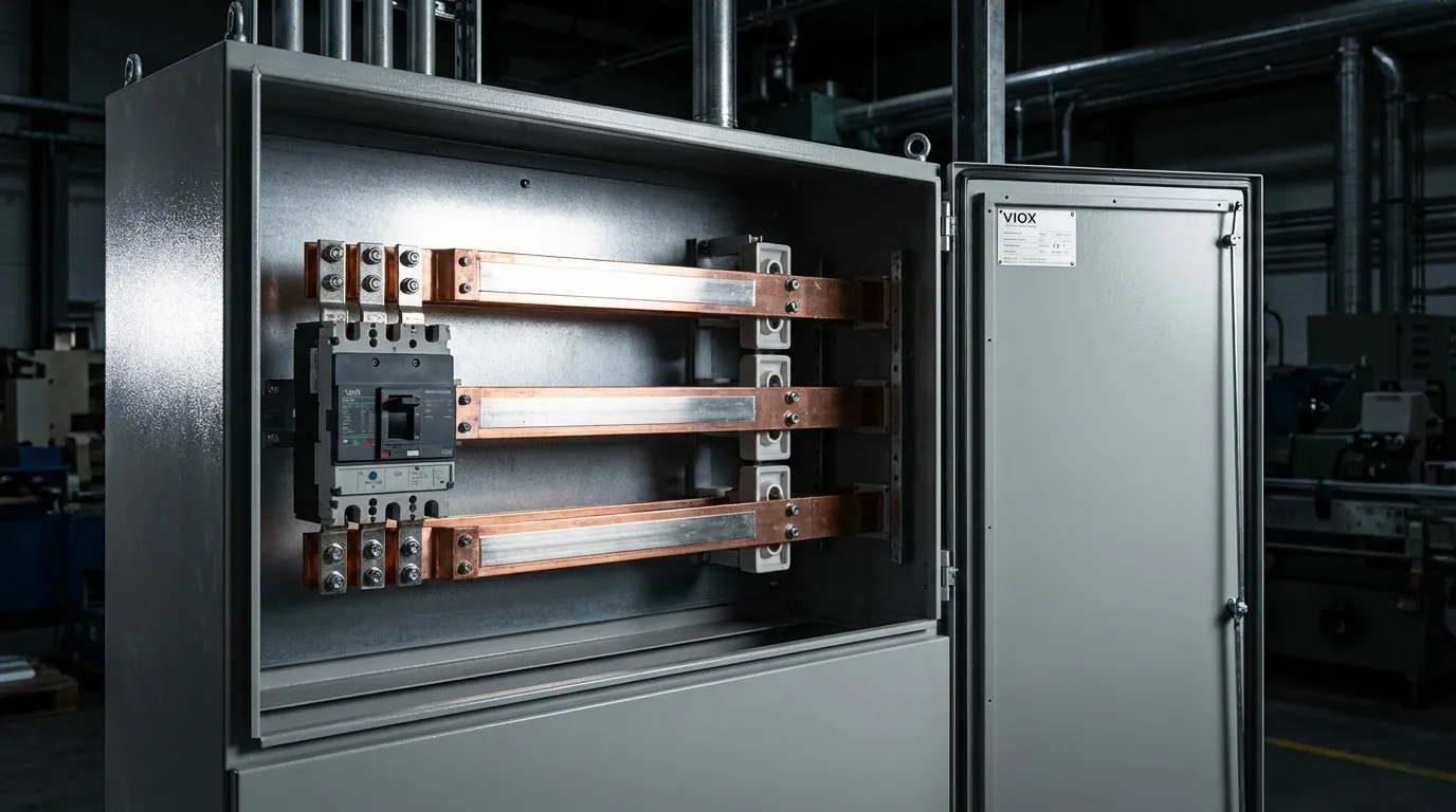
လက်တွေ့အသုံးချမှု- Panel ဒီဇိုင်းလုပ်ငန်းစဉ်
တပ်ဆင်မှုအသစ်များအတွက် ရွေးချယ်ခြင်းလုပ်ငန်းစဉ်
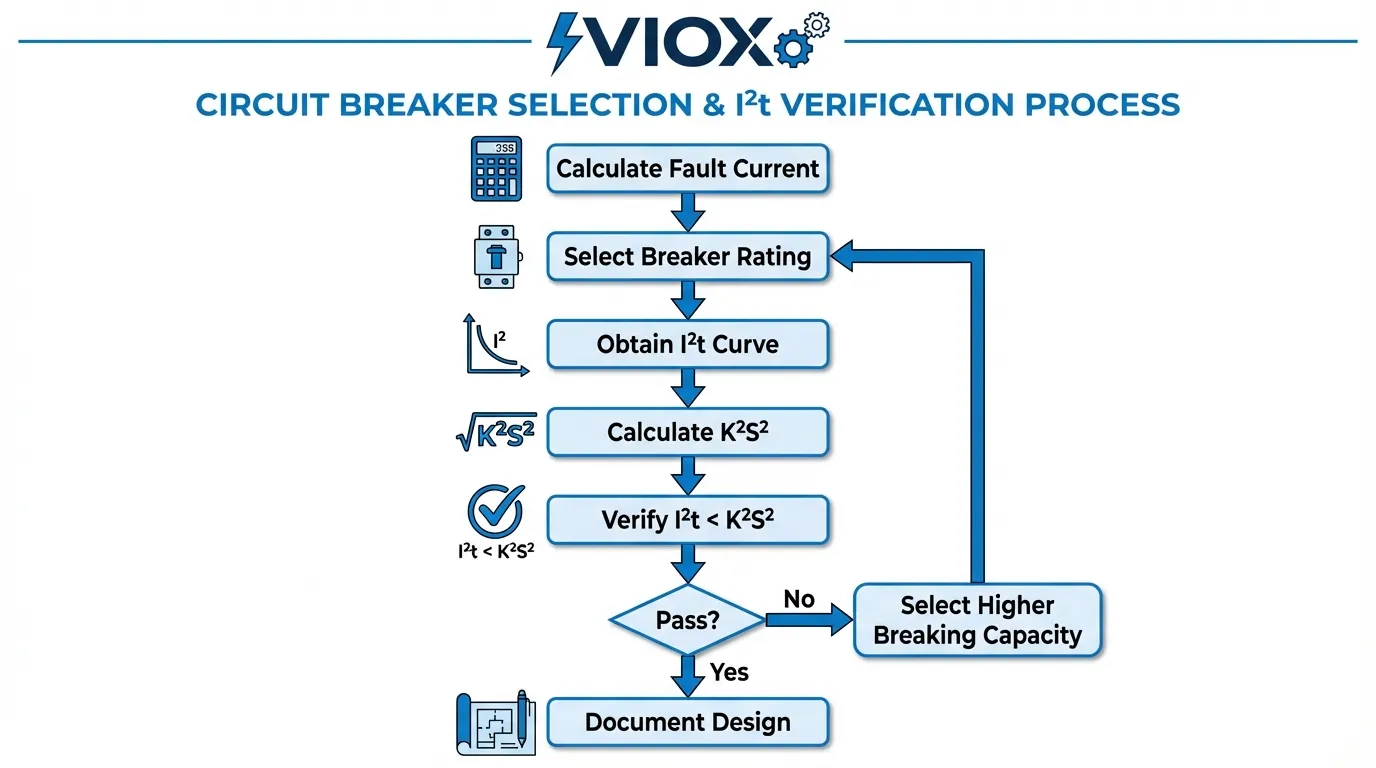
လျှပ်စစ်ဖြန့်ဖြူးရေး panel ကို ဒီဇိုင်းဆွဲသည့်အခါ သင့်လျော်သောအပူကာကွယ်မှုသေချာစေရန် ဤစနစ်တကျလုပ်ငန်းစဉ်ကို လိုက်နာပါ-
အဆင့် ၁- စနစ်ခွဲခြမ်းစိတ်ဖြာခြင်း
- စနစ် impedance ဒေတာကို အသုံးပြု၍ ဖြန့်ဖြူးရေးအမှတ်တစ်ခုစီတွင် ဖြစ်နိုင်ချေရှိသော short-circuit current အများဆုံးကို တွက်ချက်ပါ။
- တပ်ဆင်မှုရှိ conductor အမျိုးအစား၊ အရွယ်အစားနှင့် insulation ပစ္စည်းအားလုံးကို ဖော်ထုတ်ပါ။
- ပတ်ဝန်းကျင်အပူချိန်အခြေအနေများနှင့် derating factors များကို ဆုံးဖြတ်ပါ။
အဆင့် ၂- အကာအကွယ်ပစ္စည်းရွေးချယ်ခြင်း
- load current လိုအပ်ချက်များအပေါ်အခြေခံ၍ circuit breaker ratings ကိုရွေးချယ်ပါ။
- breaking capacity သည် ဖြစ်နိုင်ချေရှိသော fault current ထက်ကျော်လွန်ကြောင်း စစ်ဆေးပါ။
- fault levels မြင့်မားသော (>10kA) သို့မဟုတ် conductors သေးငယ်သော (<16mm²) နေရာများတွင် current-limiting type breakers ကိုရွေးချယ်ပါ။
အဆင့် ၃- အပူအတည်ပြုခြင်း
- ရွေးချယ်ထားသောပစ္စည်းများအတွက် breaker ထုတ်လုပ်သူထံမှ I²t curves ကိုရယူပါ။
- circuit တစ်ခုစီအတွက် conductor thermal withstand capacity (K²S²) ကို တွက်ချက်ပါ။
- ဖြစ်နိုင်ချေရှိသော fault current အတွက် breaker I²t < conductor K²S² ကို စစ်ဆေးပါ။
- ဘေးကင်းလုံခြုံရေးအနားသတ်များကို မှတ်တမ်းတင်ပါ (အနည်းဆုံး 20% အကြံပြုသည်)
အဆင့် ၄- ညှိနှိုင်းမှုစစ်ဆေးခြင်း
- upstream နှင့် downstream အကာအကွယ်ပစ္စည်းများအကြား selectivity ကို စစ်ဆေးပါ။
- backup protection I²t တန်ဖိုးများသည် downstream conductor ကန့်သတ်ချက်ထက် မကျော်လွန်ကြောင်း သေချာပါစေ။
- device ပေါင်းစပ်မှုများအတွက် ထုတ်လုပ်သူညှိနှိုင်းမှုဇယားများကို ပြန်လည်သုံးသပ်ပါ။
Retrofit နှင့် Upgrade အခြေအနေများ
load တိုးလာသောအခါ သို့မဟုတ် utility upgrades ကြောင့် fault levels ပြောင်းလဲသောအခါ တည်ရှိပြီးသားတပ်ဆင်မှုများသည် အကဲဖြတ်ရန်လိုအပ်လေ့ရှိသည်။ I²t verification လုပ်ငန်းစဉ်သည် အရေးကြီးလာသည်-
Scenario: facility တစ်ခုသည် transformer အသစ်တစ်ခုကိုထည့်သွင်းပြီး main distribution board တွင်ရရှိနိုင်သော fault current ကို 15kA မှ 35kA သို့တိုးမြှင့်ပေးသည်။.
လိုအပ်သောခွဲခြမ်းစိတ်ဖြာခြင်း:
- fault level အသစ် (35kA) တွင် တည်ရှိပြီးသား breaker I²t curves ကို ပြန်လည်သုံးသပ်ပါ။
- downstream conductor thermal withstand အားလုံးကို ပြန်လည်အတည်ပြုပါ။
- တည်ရှိပြီးသား busbars များ လုံလောက်မှုရှိမရှိ စစ်ဆေးပါ။
- standard breakers များသည် conductor I²t ကန့်သတ်ချက်ထက် ကျော်လွန်ပါက current-limiting breakers များ လိုအပ်မှုကို အကဲဖြတ်ပါ။
ဤခွဲခြမ်းစိတ်ဖြာမှုသည် တည်ရှိပြီးသား standard breakers များသည် လုံလောက်သော breaking capacity ရှိသော်လည်း မြင့်မားသော fault level တွင် I²t အလွန်အကျွံခွင့်ပြုကြောင်း မကြာခဏဖော်ပြသည်။ current-limiting breakers များသို့ အဆင့်မြှင့်တင်ခြင်းသည် အရွယ်အစားမမှန်သော conductors အားလုံးကို အစားထိုးခြင်းထက် စျေးအသက်သာဆုံးဖြေရှင်းနည်းကို ပေးလေ့ရှိသည်။.
အဖြစ်များသော ဒီဇိုင်းအမှားများနှင့် ရှောင်ရှားနည်းများ
အမှား ၁- Breakers အားလုံးသည် Current-Limiting ဖြစ်သည်ဟု ယူဆခြင်း
ပြဿနာ: circuit breakers အားလုံးသည် သိသာထင်ရှားသော current limitation ကို မပေးပါ။ Standard thermal-magnetic breakers များ၊ အထူးသဖြင့် ကြီးမားသော frame အရွယ်အစား (>630A) များသည် current-limiting effect အနည်းငယ်သာရှိသည်။ ၎င်းတို့၏ I²t curves များသည် unlimited fault energy အောက်တွင် အနည်းငယ်သာရှိသော တန်ဖိုးများကို ပြသနိုင်သည်။.
ဖြေရှင်းနည်း: breaker အမျိုးအစားကို အမြဲစစ်ဆေးပြီး ထုတ်လုပ်သူထံမှ actual I²t curves ကိုရယူပါ။ breaking capacity တစ်ခုတည်းအပေါ်အခြေခံ၍ current limitation ကို မယူဆပါနှင့်။ Current-limiting performance သည် သီးခြားဒီဇိုင်းအင်္ဂါရပ်တစ်ခုဖြစ်ပြီး မြင့်မားသော breaking capacity ၏ အလိုအလျောက်လက္ခဏာမဟုတ်ပါ။.
အမှား ၂- RMS အစား Peak Current ကို အသုံးပြုခြင်း
ပြဿနာ: အင်ဂျင်နီယာများသည် I²t တွက်ချက်မှုများအတွက် လိုအပ်သော RMS current တန်ဖိုးနှင့် limitation curves တွင်ပြထားသော peak let-through current (Ip) ကို တစ်ခါတစ်ရံတွင် ရောထွေးတတ်သည်။ ၎င်းသည် 40% သို့မဟုတ် ထို့ထက်ပိုသော အမှားများဖြစ်ပေါ်စေနိုင်သည်။.
ဖြေရှင်းနည်း: I²t curves များသည် X-axis တွင် RMS symmetrical prospective current ကို အမြဲအသုံးပြုသည်။ သင်သည် peak asymmetrical current ကို တွက်ချက်ထားပါက curve ဖတ်ရန်အတွက် RMS တန်ဖိုးကိုရရှိရန် √2 × κ (κ သည် peak factor ဖြစ်ပြီး ပုံမှန်အားဖြင့် 1.8-2.0) ဖြင့် ပိုင်းခြားပါ။.
အမှား ၃- Parallel Conductors များကို လျစ်လျူရှုခြင်း
ပြဿနာ: phase တစ်ခုလျှင် conductors အများအပြားကို paralleled လုပ်ထားသောအခါ (ကြီးမားသောတပ်ဆင်မှုများတွင် အဖြစ်များသည်) အင်ဂျင်နီယာအချို့သည် K²S² တန်ဖိုးကို conductors အရေအတွက်ဖြင့် မှားယွင်းစွာ မြှောက်ကြသည်။ ၎င်းသည် မှားယွင်းသည်၊ အဘယ်ကြောင့်ဆိုသော် fault current သည် parallel paths များအကြား ပိုင်းခြားထားသော်လည်း I²t energy သည် conductor တစ်ခုစီကို သီးခြားသက်ရောက်မှုရှိသောကြောင့်ဖြစ်သည်။.
ဖြေရှင်းနည်း: parallel conductors များအတွက် breaker I²t သည် conductor တစ်ခုအတွက် K²S² ထက်နည်းကြောင်း စစ်ဆေးပါ။ fault current ပိုင်းခြားခြင်းကို prospective current ကိုဆုံးဖြတ်သည့် စနစ် impedance တွက်ချက်မှုတွင် ထည့်သွင်းပြီးဖြစ်သည်။.
အမှား ၄- ပတ်ဝန်းကျင်အပူချိန်အကျိုးသက်ရောက်မှုများကို လျစ်လျူရှုခြင်း
ပြဿနာ: standard ဇယားများရှိ K တန်ဖိုးများသည် သတ်မှတ်ထားသော initial temperatures (ပုံမှန်အားဖြင့် continuous operation အတွက် 70°C) ကို ယူဆသည်။ ပူပြင်းသောပတ်ဝန်းကျင် (>40°C ambient) သို့မဟုတ် မြင့်မားသော load factors များပါရှိသော တပ်ဆင်မှုများသည် thermal withstand capacity ကို လျှော့ချခြင်းဖြင့် initial conductor temperatures မြင့်မားနိုင်သည်။.
ဖြေရှင်းနည်း: မြင့်မားသောပတ်ဝန်းကျင်အပူချိန်များ သို့မဟုတ် မြင့်မားသော load factors များအတွက်-
- IEC 60364-5-54 Annex A မှ ချိန်ညှိထားသော K တန်ဖိုးများကို အသုံးပြုပါ။
- K²S² ရလဒ်သို့ အပူချိန် derating factor ကို အသုံးပြုပါ။
- breaker I²t သည် နောက်ထပ်ဘေးကင်းလုံခြုံရေးအနားသတ် (>30%) ကို ပေးကြောင်း သေချာပါစေ။
အဆင့်မြင့်အကြောင်းအရာများ- Energy Limitation နှင့် Arc Flash
Arc Flash Hazard လျှော့ချရာတွင် I²t ၏အခန်းကဏ္ဍ
IEEE 1584 အရ arc flash incident energy တွက်ချက်မှုများသည် clearing time ကိုဆုံးဖြတ်ရန် breaker ၏ time-current curve ကို ရိုးရာဓလေ့အရ အသုံးပြုသည်။ သို့သော် ၎င်းတို့၏ instantaneous region တွင် လည်ပတ်နေသော current-limiting breakers များအတွက် ဤနည်းလမ်းသည် actual incident energy ကို သိသိသာသာ လွန်ကဲစွာ ခန့်မှန်းသည်။.
I²t တန်ဖိုးကို အသုံးပြု၍ arc flash energy ကို တွက်ချက်ခြင်းသည် current-limiting devices များအတွက် ပိုမိုတိကျသောရလဒ်များကို ပေးကြောင်း သုတေသနက ဖော်ပြခဲ့သည်။ ဆက်စပ်မှုမှာ-
Incident Energy (cal/cm²) ∝ √(I²t) / D²
D သည် working distance ဖြစ်သည်။ ဤချဉ်းကပ်မှုသည် time-current curve နည်းလမ်းများနှင့် နှိုင်းယှဉ်ပါက တွက်ချက်ထားသော incident energy ကို 50-70% လျှော့ချနိုင်ပြီး လိုအပ်သော PPE အမျိုးအစားများကို လျှော့ချကာ လုပ်သားဘေးကင်းမှုကို တိုးတက်စေနိုင်သည်။.
ညှိနှိုင်းမှုနှင့် Selectivity ထည့်သွင်းစဉ်းစားခြင်း
သင့်လျော်သော selectivity သည် fault နှင့်အနီးဆုံး breaker သာလည်ပတ်ရန်လိုအပ်ပြီး upstream devices များကိုပိတ်ထားရန်လိုအပ်သည်။ I²t ရှုထောင့်မှဆိုလျှင် ၎င်းသည်-
- စွမ်းအင် ခွဲခြားဆက်ဆံခြင်း: fault တည်နေရာရှိ upstream breaker ၏ I²t သည် downstream breaker ၏ စုစုပေါင်း clearing energy ထက် ကျော်လွန်ရမည်။
- အချိန် ခွဲခြားဆက်ဆံခြင်း: downstream device သည် fault ကိုရှင်းလင်းရန်အတွက် upstream device သည် လုံလောက်စွာကြာရှည်စွာ ပိတ်ထားရမည်။
- လက်ရှိ ခွဲခြားဆက်ဆံခြင်း: အချို့ကိစ္စများတွင်၊ အထက်ပိုင်းကိရိယာသည် အောက်ပိုင်းကိရိယာ၏ impedance ကြောင့် လျော့နည်းသွားသော လျှပ်စီးကြောင်းကိုသာ မြင်တွေ့ရသည်။
ထုတ်လုပ်သူများသည် မည်သည့်ကိရိယာအတွဲများသည် ရွေးချယ်နိုင်စွမ်းကို ရရှိကြောင်းပြသသည့် ညှိနှိုင်းဇယားများကို ပေးထားသော်လည်း၊ အခြေခံ I²t ဆက်ဆံရေးများကို နားလည်ခြင်းသည် ဇယားများတွင် သီးခြားအခြေအနေများကို မဖော်ပြထားသည့်အခါ အင်ဂျင်နီယာများအား အသိဉာဏ်ရှိသော ဆုံးဖြတ်ချက်များချမှတ်ရာတွင် အထောက်အကူဖြစ်စေသည်။.
သော့ထုတ်ယူမှုများ
- I²t ကွေးများသည် အပူစွမ်းအင်ကို တိုင်းတာသည်။ circuit breaker များသည် ချို့ယွင်းမှုအနှောက်အယှက်အတွင်း ဖြတ်သန်းခွင့်ပြုသည့် ampere-squared seconds (A²s) ဖြင့် တိုင်းတာသည်။
- လက်ရှိကန့်သတ် breaker များ သည် လက်ရှိကန့်သတ်မထားသော ကိရိယာများနှင့် နှိုင်းယှဉ်ပါက ချို့ယွင်းမှုစွမ်းအင်ကို 1000× သို့မဟုတ် ထို့ထက်ပို၍ လျှော့ချနိုင်ပြီး သေးငယ်သော conductor အရွယ်အစားများကို အသုံးပြုနိုင်စေသည်။
- I²t ကွေးများကို ဖတ်ရှုရန် အဆင့်ငါးဆင့် လိုအပ်သည်။: ဖြစ်နိုင်ချေရှိသော လျှပ်စီးကြောင်းကို တွက်ချက်ပါ၊ X-axis တွင် ရှာဖွေပါ၊ breaker ကွေးသို့ ခြေရာခံပါ၊ Y-axis တန်ဖိုးကို ဖတ်ပါ၊ conductor ခံနိုင်ရည်နှင့် နှိုင်းယှဉ်ပါ။
- Conductor အပူခံနိုင်ရည် ကို K²S² ကို အသုံးပြု၍ တွက်ချက်ပြီး K သည် ပစ္စည်းနှင့် insulation အမျိုးအစားပေါ်တွင် မူတည်ပြီး S သည် cross-sectional area ဖြစ်သည်။
- အတည်ပြုပုံသေနည်းသည် ရိုးရှင်းပါသည်။: Breaker I²t သည် ဖြစ်နိုင်ချေရှိသော ချို့ယွင်းမှုလျှပ်စီးကြောင်းအဆင့်တွင် conductor K²S² ထက် နည်းရမည်။
- စံချိန်စံညွှန်းများလိုက်နာ သည် breaker များအတွက် IEC 60947-2 နှင့် conductor အရွယ်အစားအတွက် IEC 60364-5-54 ကို လိုက်နာရန် လိုအပ်သည်။
- အဖြစ်များသော အမှားများ RMS/peak တန်ဖိုးများကို ရှုပ်ထွေးစေခြင်း၊ breaker အားလုံးသည် လက်ရှိကန့်သတ်ထားသည်ဟု ယူဆခြင်းနှင့် ပတ်ဝန်းကျင်အပူချိန်အကျိုးသက်ရောက်မှုများကို လျစ်လျူရှုခြင်းတို့ ပါဝင်သည်။
- Busbar အတည်ပြုခြင်း သည် တူညီသော I²t မူကို အသုံးပြုသော်လည်း အပူချိန်မြင့်တက်မှုအတွက် နောက်ထပ်တွက်ချက်မှုများ လိုအပ်သည်။
- Arc flash တွက်ချက်မှုများ သည် I²t ဒေတာမှ အကျိုးကျေးဇူးရရှိပြီး လက်ရှိကန့်သတ် breaker များအတွက် ဖြစ်ပွားမှုစွမ်းအင်ခန့်မှန်းချက်များကို မကြာခဏ လျှော့ချပေးသည်။
- Coordination and selectivity သည် အထက်ပိုင်းနှင့် အောက်ပိုင်းကာကွယ်ရေးကိရိယာများကြားရှိ သင့်လျော်သော I²t ဆက်ဆံရေးများပေါ်တွင် မူတည်သည်။
မကြာခဏမေးမေးခွန်းများ
မေး- DC circuit breaker များအတွက် I²t ကွေးများကို သုံးနိုင်ပါသလား။
အဖြေ- သုံးနိုင်သော်လည်း သတိထားပါ။ DC breaker များတွင် I²t ကွေးများရှိသော်လည်း လက်ရှိကန့်သတ်အကျိုးသက်ရောက်မှုသည် AC breaker များထက် ယေဘုယျအားဖြင့် လျော့နည်းပါသည်။ အမြဲတမ်း DC-specific ကွေးများကို သုံးပါ၊ AC breaker ဒေတာကို DC application များတွင် ဘယ်တော့မှ မသုံးပါနှင့်။. DC circuit breaker အရွယ်အစားအကြောင်း ပိုမိုလေ့လာပါ။.
မေး- ကျွန်ုပ်၏ ဖြစ်နိုင်ချေရှိသော ချို့ယွင်းမှုလျှပ်စီးကြောင်းသည် ကွေး၏အစမှတ်အောက်သို့ ကျဆင်းသွားပါက ဘာဖြစ်မလဲ။
အဖြေ- I²t ကွေးအများစုသည် လက်ရှိကန့်သတ်လုပ်ဆောင်ချက် စတင်သည့် လျှပ်စီးကြောင်းများတွင် စတင်သည် (ပုံမှန်အားဖြင့် အဆင့်သတ်မှတ်ထားသော လျှပ်စီးကြောင်း၏ 3-5×)။ ဤအကန့်အသတ်အောက်တွင်၊ breaker သည် သိသာထင်ရှားသော ကန့်သတ်ချက်မရှိဘဲ ၎င်း၏အပူ သို့မဟုတ် သံလိုက်နယ်မြေတွင် လုပ်ဆောင်သည်။ ဤနိမ့်သော လျှပ်စီးကြောင်းများအတွက်၊ I²t = I² × ရှင်းလင်းချိန်အဖြစ် I²t ကို တွက်ချက်ရန် အချိန်-လျှပ်စီးကြောင်းကွေးကို သုံးပါ။.
မေး- ရှိပြီးသား တပ်ဆင်မှုများတွင် I²t ကာကွယ်မှုကို ဘယ်လောက်ကြာကြာ ပြန်လည်အတည်ပြုသင့်လဲ။
အဖြေ- ပြန်လည်အတည်ပြုခြင်းကို အောက်ပါအခြေအနေများတွင် လိုအပ်သည်- (1) utility အဆင့်မြှင့်တင်မှုများသည် ရရှိနိုင်သော ချို့ယွင်းမှုလျှပ်စီးကြောင်းကို တိုးမြှင့်ပေးသည်၊ (2) conductor များကို အစားထိုးခြင်း သို့မဟုတ် circuit များကို တိုးချဲ့ခြင်း၊ (3) ကာကွယ်ရေးကိရိယာများကို ပြောင်းလဲခြင်း သို့မဟုတ် (4) အဓိကဝန်များကို ထည့်သွင်းခြင်း။ အကောင်းဆုံးအလေ့အကျင့်အနေဖြင့်၊ လျှပ်စစ်စနစ်လေ့လာမှုများအတွင်း (ပုံမှန်အားဖြင့် 5 နှစ်တစ်ကြိမ်) ပြန်လည်သုံးသပ်ပါ။. ခရီးစဉ်ကွေးများကို နားလည်ခြင်း သည် အပြောင်းအလဲများသည် ကာကွယ်မှုကို မည်သို့အကျိုးသက်ရောက်ကြောင်း ဖော်ထုတ်ရာတွင် အထောက်အကူဖြစ်စေသည်။.
မေး- miniature circuit breaker (MCB) များတွင် I²t ကွေးများ ရှိပါသလား။
အဖြေ- ရှိပါသည်။ IEC 60898-1 အရ MCB များတွင် ၎င်းတို့၏ breaking capacity (6kA, 10kA, etc.) နှင့် curve အမျိုးအစား (B, C, D) ပေါ်မူတည်၍ စံပြုထားသော အမြင့်ဆုံး I²t တန်ဖိုးများ ရှိသည်။ သို့သော် ထုတ်လုပ်သူများသည် အသေးစိတ်ကွေးများကို အမြဲတမ်း ထုတ်ဝေလေ့မရှိပါ။ တိကျသော အတည်ပြုခြင်းအတွက်၊ ထုတ်လုပ်သူထံမှ I²t ဒေတာကို တောင်းခံပါ သို့မဟုတ် IEC 60898-1 Annex D မှ ကာကွယ်ရေးအမြင့်ဆုံးတန်ဖိုးများကို သုံးပါ။. MCB breaking capacity နှိုင်းယှဉ်ခြင်း သည် နောက်ထပ်အကြောင်းအရာများကို ပံ့ပိုးပေးသည်။.
မေး- မတူညီသော breaker အဆင့်သတ်မှတ်ချက်များအတွက် ကွေးများကြားတွင် ဖြည့်စွက်နိုင်ပါသလား။
အဖြေ- မရပါ။ I²t ကွေးများပေါ်တွင် မတူညီသော breaker အဆင့်သတ်မှတ်ချက်များကြားတွင် ဘယ်တော့မှ မဖြည့်စွက်ပါနှင့်။ အဆင့်သတ်မှတ်ချက်တစ်ခုစီတွင် လက်ရှိကန့်သတ်ချက်ကို အကျိုးသက်ရောက်စေသော ထူးခြားသော အတွင်းပိုင်းလက္ခဏာများ ရှိသည်။ သင်၏လိုအပ်သော အဆင့်သတ်မှတ်ချက်ကို မပြပါက၊ ထုတ်လုပ်သူထံမှ သီးခြားဒေတာကို တောင်းခံပါ သို့မဟုတ် ကာကွယ်ရေးရလဒ်များအတွက် နောက်ထပ်မြင့်မားသော အဆင့်သတ်မှတ်ချက်၏ကွေးကို သုံးပါ။.
မေး- MCCB များပေါ်ရှိ I²t နှင့် Icw အဆင့်သတ်မှတ်ချက်များကြား ကွာခြားချက်ကဘာလဲ။
အဖြေ- Icw (short-time withstand current) သည် breaker တစ်ခုသည် ခရီးမထွက်ဘဲ သတ်မှတ်ထားသောအချိန် (ပုံမှန်အားဖြင့် 1 စက္ကန့်) အတွင်း သယ်ဆောင်နိုင်သော လျှပ်စီးကြောင်းဖြစ်ပြီး ညှိနှိုင်းမှုအတွက် အသုံးပြုသည်။ I²t သည် ခရီးထွက်သည့်အခါ breaker မှ ဖြတ်သန်းခွင့်ပြုသည့် အပူစွမ်းအင်ဖြစ်သည်။ ၎င်းတို့သည် မတူညီသော ရည်ရွယ်ချက်များအတွက် အသုံးပြုသည်- ရွေးချယ်နိုင်စွမ်းအတွက် Icw၊ conductor ကာကွယ်မှုအတွက် I²t။. MCCB short-time delay ရှင်းလင်းချက် သည် ဤကွာခြားချက်ကို အသေးစိတ်ဖော်ပြထားသည်။.
နိဂုံး- I²t ကို သင်၏ ဒီဇိုင်းလုပ်ငန်းစဉ်တွင် ပေါင်းစပ်ခြင်း
circuit breaker I²t ကွေးများကို နားလည်ပြီး သင့်လျော်စွာ အသုံးပြုခြင်းသည် အပူကာကွယ်မှုကို သီအိုရီဆိုင်ရာ စိုးရိမ်မှုမှ လက်တွေ့ကျသော ဒီဇိုင်းကိရိယာအဖြစ်သို့ ပြောင်းလဲပေးသည်။ အတည်ပြုခြင်းလုပ်ငန်းစဉ်—ကွေးများကိုဖတ်ခြင်း၊ conductor ခံနိုင်ရည်ကို တွက်ချက်ခြင်းနှင့် လုံလောက်သော အနားသတ်များကို အတည်ပြုခြင်း—သည် circuit တစ်ခုလျှင် မိနစ်အနည်းငယ်သာ ကြာသော်လည်း ကုန်ကျစရိတ်ကြီးမားသော ချို့ယွင်းမှုများနှင့် ဘေးကင်းရေးအန္တရာယ်များကို ကာကွယ်ပေးသည်။.
ခေတ်မီလျှပ်စစ်တပ်ဆင်မှုများသည် utility grid များ အားကောင်းလာပြီး ဖြန့်ဝေထားသော ထုတ်လုပ်မှုများ တိုးပွားလာသည်နှင့်အမျှ ချို့ယွင်းမှုလျှပ်စီးကြောင်းအဆင့်များ တိုးများလာခြင်းကို ရင်ဆိုင်နေရသည်။ တစ်ချိန်တည်းမှာပင် စီးပွားရေးဖိအားများသည် conductor အရွယ်အစားကို အနည်းဆုံးလက်ခံနိုင်သော တန်ဖိုးများဆီသို့ တွန်းပို့နေသည်။ ဤပေါင်းစည်းမှုသည် I²t အတည်ပြုခြင်းကို အကြံပြုရုံသာမက ဘေးကင်းပြီး ကုဒ်နှင့်ကိုက်ညီသော ဒီဇိုင်းများအတွက် မရှိမဖြစ်လိုအပ်စေသည်။.
VIOX Electric သည် ကျွန်ုပ်တို့၏ထုတ်ကုန်အကွာအဝေးရှိ လက်ရှိကန့်သတ် circuit breaker အားလုံးအတွက် ပြည့်စုံသော I²t ကွေးများနှင့် နည်းပညာဆိုင်ရာ ပံ့ပိုးမှုများကို ပေးပါသည်။ ကျွန်ုပ်တို့၏ အင်ဂျင်နီယာအဖွဲ့သည် အပူအတည်ပြုတွက်ချက်မှုများကို ကူညီပေးပြီး ချို့ယွင်းမှုအဆင့်များသည် conductor အပူကန့်သတ်ချက်များနှင့် နီးကပ်လာသည့် စိန်ခေါ်မှုရှိသော application များအတွက် အကောင်းဆုံး breaker ရွေးချယ်မှုများကို အကြံပြုနိုင်ပါသည်။.
ညှိနှိုင်းမှုအဆင့်များစွာပါဝင်သော ရှုပ်ထွေးသော တပ်ဆင်မှုများအတွက်၊, busbar selection, သို့မဟုတ် အထူးပြု application များကဲ့သို့ ဆိုလာပေါင်းစပ်သေတ္တာများ, I²t-based ကာကွယ်ရေးနည်းဗျူဟာများ၏ သီအိုရီဆိုင်ရာ အခြေခံမူများနှင့် လက်တွေ့အသုံးချမှုကို နားလည်သော အတွေ့အကြုံရှိ လျှပ်စစ်အင်ဂျင်နီယာများနှင့် တိုင်ပင်ပါ။.
သင့်လျော်သောအပူအတည်ပြုခြင်းတွင် ရင်းနှီးမြှုပ်နှံမှုသည် ပိုမိုကောင်းမွန်သော ဘေးကင်းမှု၊ ချို့ယွင်းမှုများအတွင်း ပစ္စည်းကိရိယာများ ပျက်စီးမှုလျော့နည်းခြင်း၊ အာမခံစရိတ်သက်သာခြင်းနှင့် ကမ္ဘာတစ်ဝှမ်းရှိ တင်းကျပ်လာသော လျှပ်စစ်ကုဒ်များနှင့် လိုက်လျောညီထွေဖြစ်ခြင်းတို့မှတစ်ဆင့် အကျိုးအမြတ်များရရှိစေပါသည်။ သင်၏ circuit breaker ရွေးချယ်မှုလုပ်ငန်းစဉ်တွင် I²t ကွေးခွဲခြမ်းစိတ်ဖြာခြင်းကို စံအဆင့်တစ်ခုအဖြစ် ပြုလုပ်ပါ—သင်၏ conductor များ နှင့် သင်၏ဖောက်သည်များသည် သင့်အား ကျေးဇူးတင်ပါလိမ့်မည်။.
