Pada halaman ini
Jawapan Pantas: Pemasa On Delay lwn Off Delay
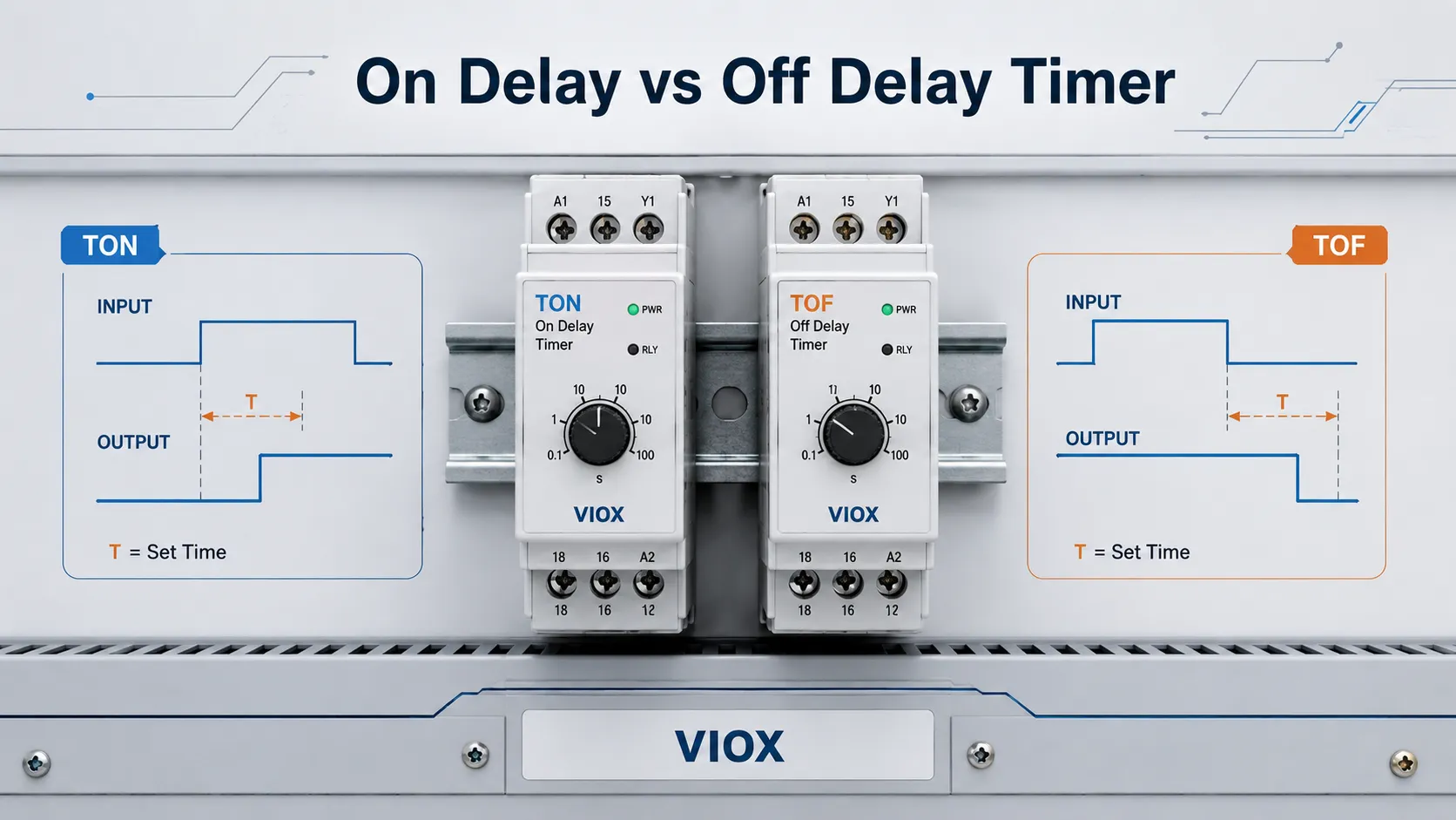
An pemasa on delay menunggu selepas isyarat input dihidupkan (ON) sebelum memberi tenaga kepada output. Ia juga dipanggil TON, pemasa on delay, delay-on-make, atau delay-on-operate.
An pemasa off delay memberi tenaga kepada output serta-merta apabila input dihidupkan (ON), kemudian mengekalkan output hidup (ON) untuk tempoh masa yang ditetapkan selepas input dimatikan (OFF). Ia juga dipanggil TOF, pemasa tunda mati, tunda semasa putus, atau tunda semasa lepas.
Dalam satu ayat: tunda hidup mengawal bila beban bermula; tunda mati mengawal berapa lama beban terus berjalan selepas arahan dialihkan.
Pengambilan Utama
- TON = Pemasa Tunda Hidup. Input mesti kekal HIDUP selama masa pratetap sebelum output bertukar HIDUP.
- TOF = Pemasa Tunda Mati. Output bertukar HIDUP serta-merta, kemudian kekal HIDUP selama masa pratetap selepas input bertukar MATI.
- guna tunda hidup (on delay) untuk penjujukan motor, tunda anti-kitaran-pendek pemampat, tunda mula kontaktor, dan penapisan isyarat palsu.
- guna tunda mati untuk pasca-jalan kipas penyejuk, jalan-terus pam, pembersihan pengudaraan, tunda lampu tangga, dan penutupan terkawal.
- Pemasa tunda mati (off delay) biasa mungkin masih memerlukan kuasa kawalannya sendiri semasa sedang menunda. Jika pemasa mesti mengekalkan output selepas kehilangan kuasa sepenuhnya, semak fungsi tunda mati (power-off delay) sebenar.
Jadual Perbandingan Pemasa Tunda Hidup (On Delay) vs Tunda Mati (Off Delay)
| item | Pemasa Lengah Hidup (TON) | Pemasa Lengah Mati (TOF) |
|---|---|---|
| Fungsi asas | Menunda output HIDUP (ON) | Menunda output MATI (OFF) |
| Pemasaan bermula apabila | Input bertukar ON | Input dimatikan (OFF) |
| Output apabila input bertukar ON | Menunggu semasa masa pratetap, kemudian bertukar ON | Bertukar ON serta-merta |
| Output apabila input bertukar OFF | Bertukar OFF serta-merta | Kekal ON semasa masa pratetap |
| Nama-nama umum | Lengah-hidup, lengah-kendali, pemasa lengah hidup | Lengah-pada-putus, lengah-pada-lepas, lengah masa pemasa mati |
| Istilah PLC | TON | TOF |
| Tujuan utama | Mencegah permulaan awal | Mengekalkan larian terkawal |
| Kegunaan motor tipikal | Permulaan berjujukan, lengah anti-kitaran-pendek | Lengah kipas penyejuk, larian pam |
| Kesilapan biasa | Menjangkakan output serta-merta | Mengandaikan ia berfungsi selepas kehilangan kuasa sepenuhnya |
Geganti Masa On-Delay: Prinsip Kerja dan Urutan
Pemasa on-delay mula mengira masa apabila input kawalan atau gegelungnya ditenagakan. Semasa tempoh masa pratetap, sesentuh output kekal dalam keadaan normalnya. Jika input kekal ada sehingga masa pratetap tamat, output bermasa akan berubah keadaan.
Bagi output geganti, ini biasanya bermaksud:
- sesentuh biasanya terbuka bermasa akan tertutup selepas kelewatan;
- sesentuh biasanya tertutup bermasa akan terbuka selepas kelewatan;
- jika input hilang sebelum kelewatan selesai, pemasa akan ditetapkan semula dan output tidak berubah keadaan.
Urutan Kerja Pemasa On-Delay
| Langkah | Input | Pemasa | Output |
|---|---|---|---|
| 1 | DIMATIKAN | Reset | DIMATIKAN |
| 2 | HIDUPKAN | Mula mengira | Masih MATI |
| 3 | Kekal HIDUP sehingga masa pratetap | Mencapai masa pratetap | HIDUPKAN |
| 4 | Kekal HIDUP | Selesai | Kekal HIDUP |
| 5 | MATI | Set semula | Bertukar OFF serta-merta |
Tingkah laku ini berguna apabila mesin tidak sepatutnya bermula daripada isyarat seketika, susutan voltan, lantunan suis, atau input penderia yang tidak stabil.
Aplikasi On Delay Biasa
- Memulakan motor satu demi satu untuk mengelakkan arus masuk serentak
- Melengahkan mula semula pemampat selepas berhenti seketika
- Memulakan penghantar hanya selepas isyarat penderia kekal stabil
- Melengahkan gegelung kontaktor selepas kuasa kawalan kembali pulih
- Pemasaan peralihan star-delta di mana pemasa pemula khusus tidak digunakan
- Menapis isyarat palsu yang singkat daripada suis had, suis apung, atau suis tekanan
Geganti Masa Off-Delay: Prinsip Kerja dan Urutan
Pemasa off-delay menukar output serta-merta apabila input dihidupkan (ON). Kelewatan berlaku kemudian, selepas input dimatikan (OFF). Semasa tempoh off-delay, output kekal bertenaga. Apabila masa pratetap tamat, output kembali ke keadaan asalnya.
Bagi output geganti, ini biasanya bermaksud:
- sesentuh output biasanya terbuka (normally open) tertutup serta-merta apabila input dikenakan;
- sesentuh kekal tertutup selepas input dialihkan;
- sesentuh terbuka hanya selepas masa off-delay pratetap telah berlalu.
Urutan Operasi Pemasa Off-Delay
| Langkah | Input | Pemasa | Output |
|---|---|---|---|
| 1 | DIMATIKAN | Reset | DIMATIKAN |
| 2 | HIDUPKAN | Belum bermasa lagi | Bertukar ON serta-merta |
| 3 | Kekal HIDUP | Output kekal aktif | Kekal HIDUP |
| 4 | MATI | Mula mengira | Masih HIDUP |
| 5 | Masa pratetap tamat | Selesai | MATI |
Tingkah laku ini berguna apabila peralatan perlu terus berjalan seketika selepas isyarat arahan dialihkan.
Aplikasi Biasa Kelewatan Mati (Off Delay)
- Kipas penyejuk berjalan selepas motor atau pemacu berhenti
- Pam terus berjalan selepas suis aras terbuka
- Pembersihan kipas ekzos selepas proses tamat
- Kelewatan lampu tangga atau koridor
- Pelepasan tertunda litar kontaktor tambahan
- Memastikan penghantar terus berjalan seketika untuk mengosongkan produk selepas arahan berhenti
Gambar rajah pemasaan TON lwn TOF
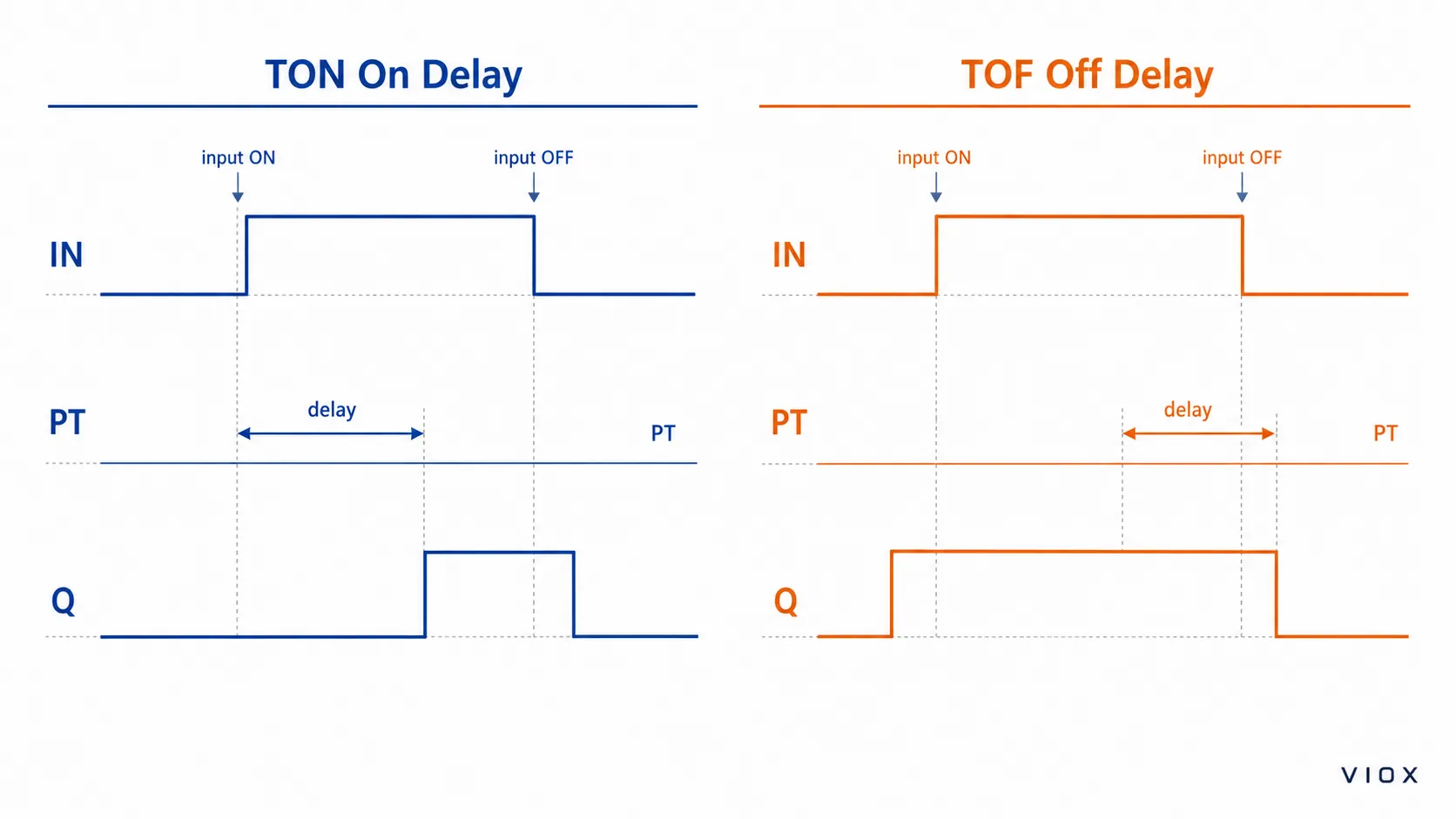
Cara paling mudah untuk membaca perbezaannya adalah dengan membandingkan pemasaan input dan output.
| Titik pemasaan | Isyarat input | Output TON | Output TOF |
|---|---|---|---|
| Sebelum input | DIMATIKAN | DIMATIKAN | DIMATIKAN |
| Input bertukar ON | HIDUP | MATI semasa masa pratetap | HIDUP serta-merta |
| Input kekal HIDUP | HIDUP | HIDUP selepas masa pratetap | HIDUP |
| Input dimatikan (OFF) | DIMATIKAN | MATI serta-merta | HIDUP semasa masa pratetap |
| Lengah tamat tempoh | DIMATIKAN | DIMATIKAN | DIMATIKAN |
Dalam gambar rajah pemasaan, gunakan tiga baris: Input (IN), Masa Praset (PT), dan Output (Q). Untuk TON, jurang visual utama adalah antara input HIDUP dan output HIDUP. Untuk TOF, jurang visual utama adalah antara input OFF dan output OFF.
Gambar rajah ini harus dianggap sebagai pemeriksaan pertama sebelum pendawaian atau penggantian. Jika bentuk gelombang output yang dijangkakan tidak sepadan dengan jujukan mesin, fungsi pemasa yang dipilih adalah salah walaupun voltan bekalan dan nombor terminal kelihatan betul.
TON berbanding TOF dalam Logik PLC
Dalam pengaturcaraan pengawal logik boleh atur cara (PLC), TON dan TOF adalah blok fungsi pemasa yang biasa. IEC 61131-3 ialah rangka kerja piawaian antarabangsa utama untuk bahasa pengaturcaraan PLC dan konsep blok fungsi, walaupun perincian pelaksanaan sebenar masih bergantung pada platform PLC.
| Istilah PLC | Maknanya | Parameter tipikal |
|---|---|---|
| TON | Pemasa On Delay | IN, PT, Q, ET |
| TOF | Penangguhan Masa Mati | IN, PT, Q, ET |
| IN | Keadaan input | Pencetus Boolean |
| PT | Masa pratetap | Masa penangguhan sasaran |
| ET | Masa yang telah berlalu | Masa terkumpul semasa |
| Q | Output | Hasil pemasa |
Logik TON dalam Bahasa Mudah
bila IN menjadi benar, ET mula mengira. Q menjadi benar hanya selepas ET mencapai PT. Jika IN menjadi palsu sebelum masa praset, ET ditetapkan semula dan Q kekal palsu.
Logik TOF dalam Bahasa Mudah
bila IN adalah benar, Q menjadi benar serta-merta. Apabila IN menjadi palsu, ET mula mengira. Q kekal benar sehingga ET mencapai PT, kemudian menjadi palsu.
Pemasa PLC dan geganti masa fizikal menyelesaikan masalah pemasaan yang serupa, tetapi ia bukanlah produk yang sama. Pemasa PLC ialah logik perisian di dalam pengawal. Geganti masa ialah peranti perkakasan dengan terminal, gegelung atau voltan bekalan, sesentuh keluaran, julat pemasaan, dan kadaran sesentuh.
Untuk terminologi perkakasan asas, lihat panduan VIOX mengenai apakah itu geganti masa.
Simbol Geganti Pemasa dan Istilah Sentuhan
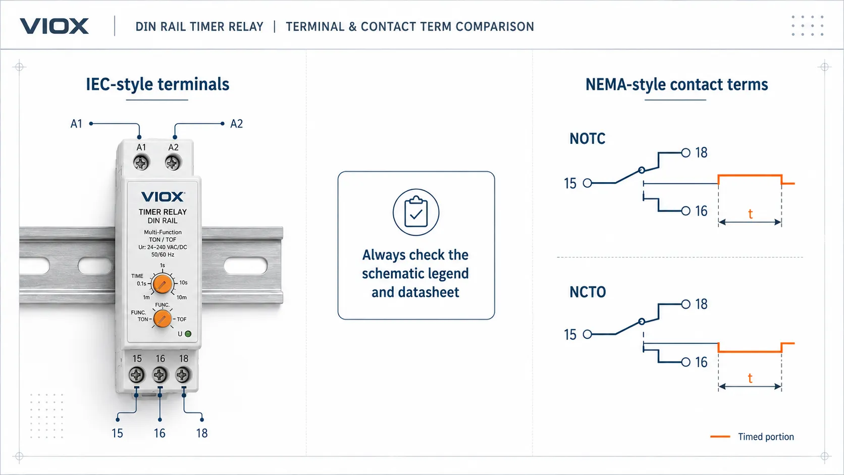
Simbol geganti pemasa berbeza mengikut piawaian lukisan, pengilang, dan legenda projek. Sentiasa semak legenda skematik dan helaian data pemasa sebelum membuat pendawaian.
Terdapat dua cara biasa jurutera menemui penerangan sentuhan pemasa:
- pendawaian gaya IEC dan rujukan terminal, seperti A1/A2 untuk bekalan dan 15/16/18 untuk sentuhan tukar ganti.
- Istilah kelakuan kontaktor gaya NEMA / Amerika Utara, seperti NOTC atau NCTO, yang menerangkan sama ada sesentuh adalah biasanya terbuka atau biasanya tertutup dan sama ada perubahan tersebut bermasa.
Sistem ini sering bercampur dalam dokumentasi panel antarabangsa, terutamanya apabila mesin direka di satu rantau dan diservis di rantau lain. Jadikan legenda skematik dan helaian data sebagai autoriti, bukan singkatan itu sahaja.
Dalam banyak lukisan kawalan, sesentuh bermasa mungkin diterangkan melalui kelakuan keadaan sesentuh:
| Notasi sesentuh | Maknanya | Penggunaan tipikal |
|---|---|---|
| NOTC | Biasanya Terbuka, Bermasa Tertutup | Sesentuh tertutup selepas kelewatan |
| NCTO | Biasanya tertutup, masa terbuka | Sentuhan terbuka selepas kelewatan |
| NOTO | Biasanya terbuka, masa terbuka | Sentuhan berkaitan dengan kelakuan pembukaan tertunda |
| NCTC | Biasanya tertutup, masa tertutup | Satu sesentuh adalah berkaitan dengan kelakuan penutupan tertunda |
Untuk tujuan pengajaran, pemasa on-delay sering ditunjukkan sebagai sesentuh biasanya terbuka yang tertutup selepas masa yang ditetapkan. Pemasa off-delay sering ditunjukkan oleh kelakuan pelepasan tertunda, di mana output kembali kepada normal hanya selepas kelewatan tamat.
Notasi simbol sahaja tidak memberitahu anda voltan bekalan, kadaran sesentuh, julat pemasaan, kelakuan set semula, atau sama ada peranti tersebut adalah pemasa fungsi tunggal atau pelbagai fungsi. Butiran tersebut mesti diperoleh daripada helaian data produk.
Logik Pendawaian: Geganti On Delay lwn Off Delay
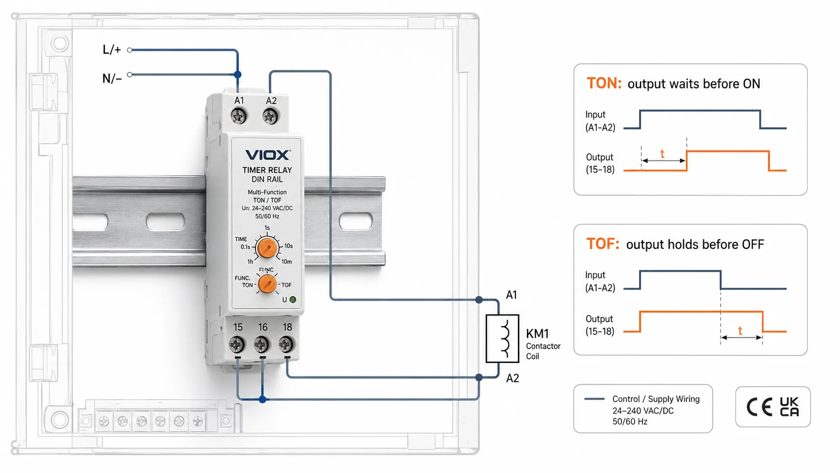
Kebanyakan geganti pemasa industri merangkumi:
- terminal bekalan seperti A1/A2;
- sesentuh output bermasa seperti 15/16/18 atau 25/26/28;
- pemilih julat masa;
- pemilih fungsi pada model pelbagai fungsi;
- kadangkala input pencetus yang berasingan.
Pendawaian mungkin kelihatan serupa, tetapi fungsi pemasaan mengubah hasilnya:
| Soalan pendawaian | Jawapan tunda hidup (On delay) | Jawapan tunda mati (Off delay) |
|---|---|---|
| Bilakah pemasaan bermula? | Apabila input atau gegelung ditenagakan | Apabila input atau pencetus dialihkan |
| Adakah output ditenagakan serta-merta? | Tiada | Ya |
| Adakah output terputus serta-merta apabila input dialihkan? | Ya | Tiada |
| Apakah yang perlu diperiksa terlebih dahulu? | Kestabilan input dan julat masa tunda | Kuasa kawalan semasa pemasaan dan kelakuan pelepasan |
Untuk contoh pendawaian yang lebih terperinci, gunakan VIOX’s panduan gambar rajah pendawaian geganti lengah masa.
Aplikasi Pemasa Lengah Motor
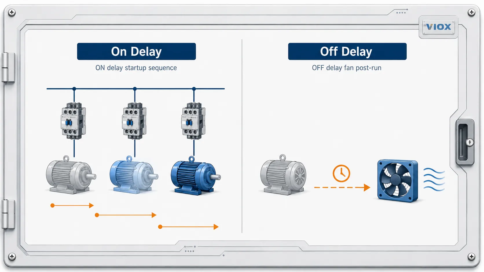
A pemasa lengah motor boleh jadi sama ada lengah hidup atau lengah mati. Pilihan yang tepat bergantung kepada sama ada litar motor memerlukan pemulaan tertunda, penutupan tertunda, atau kawalan tambahan tertunda.
| Keperluan kawalan motor | Fungsi yang lebih baik | Sebab |
|---|---|---|
| Mulakan berbilang motor secara berjujukan | Lengah hidup | Mengurangkan permintaan permulaan serentak |
| Mencegah kitaran singkat pemampat | Lengah hidup | Menyekat permulaan semula serta-merta |
| Melengahkan peralihan bintang-delta | Geganti masa lengah hidup (on delay) atau geganti masa bintang-delta khusus | Mengawal pemasaan peralihan |
| Memastikan kipas penyejuk terus berjalan selepas motor berhenti | Lengah mati (off delay) | Menyingkirkan haba baki |
| Pastikan pam terus berjalan selepas isyarat aras hilang | Lengah mati (off delay) | Membersihkan baki bendalir |
| Pastikan pengudaraan terus berjalan selepas proses ditutup | Lengah mati (off delay) | Menyingkirkan haba, wasap, atau isi padu udara |
Untuk konteks pendawaian pemula motor, lihat panduan VIOX mengenai cara mendawai geganti masa untuk pemula motor.
Jangan gunakan pemasa untuk menyembunyikan masalah perlindungan. Jika motor berulang kali menyebabkan pemutus litar, geganti beban lampau, atau kontaktor terpelantik, periksa arus motor, tetapan beban lampau, kaedah permulaan, pendawaian, kadaran kontaktor, dan beban mekanikal sebelum menambah lengah masa.
Kadaran Sentuh: AC-15 dan DC-13 Adalah Penting
Sentuh geganti masa sering digunakan untuk menukar gegelung kontaktor, solenoid, lampu pandu, kipas kecil, injap, atau input kawalan. Beban-beban ini tidak memberi tekanan kepada sentuh dengan cara yang sama.
Bagi peranti litar kawalan, kategori penggunaan IEC 60947-5-1 seperti AC-15 dan DC-13 adalah penting:
| Kategori | Jenis beban tipikal | Mengapa ia penting |
|---|---|---|
| AC-15 | Beban kawalan elektromagnet AC, seperti gegelung kontaktor | Arus masuk gegelung dan pemutusan induktif memberi tekanan kepada sentuh geganti |
| DC-13 | Beban kawalan elektromagnet DC, seperti solenoid DC | Arka DC lebih sukar diputuskan kerana tiada lintasan sifar AC semula jadi |
Jika sesentuh geganti masa hanya berkadar untuk beban rintangan, jangan anggap ia boleh menukar beban induktif dengan selamat pada arus yang sama. Gunakan kontaktor atau geganti perantara apabila beban yang dikawal melebihi kadaran sesentuh geganti masa.
Untuk penjelasan yang lebih mendalam, lihat panduan VIOX mengenai mengapa sesentuh geganti masa gagal pada beban kearuhan.
Kelewatan Matikan Kuasa (Power-Off Delay) lwn Kelewatan Mati (Off Delay): Jangan Keliru Antaranya
Pemasa kelewatan mati standard melengahkan pelepasan output selepas isyarat kawalan dialihkan, tetapi ia mungkin masih memerlukan bekalan kuasanya sendiri semasa sedang menetapkan masa. Jika pemasa kehilangan semua kuasa, ia mungkin menetap semula dengan serta-merta.
Gunakan pemasa lengah mati kuasa sebenar hanya apabila helaian data menyatakan dengan jelas bahawa peranti boleh mengekalkan output atau pemasaan selepas bekalan kuasa dialihkan. Bergantung pada reka bentuk, ini mungkin memerlukan simpanan tenaga dalaman, bekalan tambahan yang berasingan, atau seni bina kawalan yang lain.
Perbezaan ini penting dalam litar sambungan kipas, litar kawalan kecemasan, dan urutan penutupan. Jika output mesti kekal aktif semasa gangguan kuasa sepenuhnya, sahkan tingkah laku kelewatan matikan kuasa yang tepat sebelum memilih geganti tersebut.
Cara Memilih Antara Kelewatan Hidup (On Delay) dan Kelewatan Mati (Off Delay)
Gunakan peraturan lapangan yang mudah ini:
- Jika mesin perlu menunggu sebelum memulakan, pilih lengah hidup / TON.
- Jika mesin perlu terus berjalan selepas arahan dialihkan, pilih lengah mati / TOF.
Selepas memilih fungsi pemasaan, semak spesifikasi ini:
| Item pemilihan | Perkara yang perlu disahkan |
|---|---|
| Voltan bekalan | voltan kawalan AC atau DC pada A1/A2 |
| Julat masa | Masa praset minimum dan maksimum |
| Ketepatan pemasaan | Kebolehulangan yang diperlukan untuk proses tersebut |
| Jenis sesentuh output | SPDT, DPDT, kelakuan NO/NC bermasa |
| Penarafan sesentuh | Penarafan rintangan dan kategori beban induktif |
| Kelakuan set semula | Apa yang berlaku jika input jatuh atau kuasa terputus |
| Melekap | Rel DIN, soket, panel, atau PCB |
| Persekitaran | Suhu, kelembapan, getaran, perlindungan kepungan |
| Piawaian dan dokumentasi | Bukti kelulusan IEC, UL, atau lain-lain yang diperlukan oleh projek |
Untuk pemilihan produk yang lebih luas, gunakan VIOX’s Panduan pemilihan geganti pemasa atau nilai yang tersedia Timer Relay pilihan.
Kesilapan Lazim
Kesilapan 1: Menggunakan Off Delay Apabila Anda Memerlukan Delayed Start
Jika beban mesti bermula hanya selepas kelewatan yang ditetapkan, anda memerlukan on delay. Pemasa off delay akan bertenaga serta-merta, yang merupakan tingkah laku yang bertentangan.
Kesilapan 2: Mengandaikan Off Delay Berfungsi Selepas Kehilangan Kuasa
Off delay tidak selalunya sama dengan power-off delay. Jika bekalan pemasa hilang, geganti off-delay standard mungkin ditetapkan semula. Semak helaian data apabila aplikasi bergantung pada output yang bertahan selepas kehilangan kuasa.
Kesilapan 3: Mengabaikan Voltan Gegelung berbanding Voltan Beban
Voltan bekalan geganti masa dan voltan beban yang ditukar tidak semestinya sama. Geganti masa 24 V DC boleh menukar beban AC melalui terminal keluarannya hanya jika terminal keluaran tersebut berkadar untuk voltan dan jenis beban itu.
Kesilapan 4: Menukar Beban Induktif Tanpa Penindasan
Gegelung kontaktor, solenoid, dan injap boleh menghasilkan lonjakan voltan apabila dinyah-tenaga. Bergantung pada litar, gunakan RC snubber, MOV, diod flyback, atau geganti antara muka yang sesuai mengikut reka bentuk peralatan.
Kesilapan 5: Menggantikan Geganti Masa Tanpa Menyemak Gambar Rajah Pemasaan
Dua geganti masa boleh berkongsi voltan dan susun atur pin yang sama tetapi berkelakuan berbeza. Sentiasa bandingkan gambar rajah pemasaan, keadaan set semula, input pencetus, keadaan sesentuh, dan fungsi yang dipilih sebelum penggantian.
Kesilapan 6: Menggunakan Geganti Masa untuk Membaiki Kerosakan Mekanikal atau Perlindungan
Geganti masa lengah boleh menjujukan peralatan, tetapi ia tidak sepatutnya menutup perjalanan beban lampau, pemanasan melampau, voltan tidak stabil, getaran kontaktor, atau peranti perlindungan motor yang bersaiz tidak betul.
Nota Kejuruteraan Pengilang
Bagi pengilang geganti masa, pemeriksaan kritikal bukan sekadar tombol masa dan paparan. Geganti masa yang boleh dipercayai mesti disahkan untuk kebolehulangan masa, operasi sesentuh, keselamatan terminal, prestasi penebat, dan kesesuaian beban sebelum ia sampai ke panel kawalan. Dalam penyumberan B2B, minta gambar rajah fungsi masa, kadaran sesentuh di bawah beban rintangan dan induktif, julat suhu operasi, dan dokumentasi standard yang terpakai dan bukannya memilih hanya berdasarkan voltan dan julat masa.
Bagi gegelung kontaktor, solenoid, dan beban elektromagnet lain, perincian praktikal yang paling penting ialah tugas sesentuh. Geganti yang berfungsi dengan baik pada beban rintangan kecil mungkin gagal lebih awal pada beban kawalan induktif AC-15 atau DC-13 jika aplikasi tidak diperiksa dengan betul.
Soalan Lazim
Mengapakah gambar rajah masa lebih boleh dipercayai daripada nama pemasa?
Nama pemasa sering diterjemahkan secara berbeza merentas pengilang, tetapi gambar rajah masa menunjukkan logik sebenar. Bandingkan bentuk gelombang input dan bentuk gelombang output terlebih dahulu. Jika output menunggu sebelum bertukar ON, ia adalah kelakuan on-delay. Jika output menunggu sebelum bertukar OFF, ia adalah kelakuan off-delay.
Fungsi pemasa yang manakah lebih baik untuk kelewatan kipas penyejuk motor?
Gunakan pemasa off delay. Kipas penyejuk harus berjalan apabila motor berjalan dan terus berjalan untuk tempoh masa yang ditetapkan selepas motor berhenti. Pemasa on delay akan melambatkan permulaan kipas dan berhenti serta-merta apabila arahan dialihkan, yang biasanya merupakan kelakuan yang salah untuk penyejukan selepas operasi.
Bolehkah satu geganti masa berbilang fungsi menyediakan kedua-dua on delay dan off delay?
Ya, banyak geganti masa berbilang fungsi boleh menyediakan kedua-dua fungsi tersebut. Mod yang dipilih mesti disahkan sebelum pendawaian dan pentauliahan kerana terminal yang sama mungkin berkelakuan berbeza dalam mod yang berlainan.
Mengapakah pemasa tunda mati (off delay timer) kadangkala gagal untuk bertahan selepas kehilangan kuasa?
Banyak pemasa tunda mati memerlukan kuasa kawalan semasa tempoh pemasaan. Apabila bekalan hilang sepenuhnya, litar pemasaan dalaman mungkin ditetapkan semula. Jika output mesti kekal aktif selepas kehilangan bekalan, tentukan pemasa tunda mati kuasa sebenar (true power-off delay timer) atau sediakan bekalan kawalan tambahan.
Apakah kadaran sesentuh yang perlu saya semak untuk gegelung kontaktor, solenoid, atau injap?
Untuk gegelung kawalan dan solenoid, semak kadaran kawalan induktif seperti AC-15 untuk beban AC atau DC-13 untuk beban DC yang berkenaan. Jangan hanya bergantung pada kadaran amp rintangan yang dicetak pada pemasa.
Bilakah saya perlu menggunakan geganti masa berbanding arahan TON atau TOF PLC?
Gunakan geganti masa apabila fungsi tersebut mesti berfungsi dalam litar kawalan berwayar keras, panel kendiri kecil, atau pengubahsuaian di mana tiada PLC tersedia. Gunakan arahan TON atau TOF PLC apabila mesin sudah mempunyai PLC dan logik pemasaan perlu disepadukan dengan syarat program, penggera, saling kunci (interlock), atau tetapan HMI.
Adakah nombor terminal IEC dan nama sesentuh pemasa gaya NEMA adalah perkara yang sama?
Tidak. Nombor terminal IEC seperti A1/A2 dan 15/16/18 mengenal pasti terminal bekalan dan sesentuh. Istilah gaya NEMA seperti NOTC atau NCTO menerangkan kelakuan sesentuh bermasa. Lukisan mungkin menggunakan kedua-duanya, jadi sentiasa baca legenda skematik bersama-sama dengan helaian data produk.
Apakah yang perlu saya periksa semasa menggantikan geganti masa tunda hidup (on-delay) atau tunda mati (off-delay) yang lama?
Periksa voltan bekalan, fungsi pemasaan, julat pemasaan, susun atur terminal, konfigurasi sesentuh, kelakuan set semula, kadaran sesentuh, gaya pemasangan, dan sama ada litar asal menggunakan input pencetus yang berasingan. Jangan gantikan geganti hanya kerana soket atau bilangan pin kelihatan serupa.
Mengapakah output geganti pemasa bergetar (chatter) atau set semula sebelum masa yang ditetapkan?
Punca biasa termasuk voltan kawalan yang tidak stabil, lantunan suis (switch bounce), hingar penderia, mod fungsi yang salah, terminal longgar, gangguan elektromagnet daripada kontaktor atau pemacu frekuensi boleh ubah, atau bekalan kuasa yang kurang kadaran. Periksa isyarat input dengan meter atau osiloskop sebelum menggantikan pemasa.
Apakah cara paling selamat untuk mengesahkan sama ada pemasa adalah TON atau TOF di lapangan?
Nyahtenagakan dan periksa helaian data terlebih dahulu. Semasa ujian terkawal, bekalkan voltan kawalan berkadar dan perhatikan sama ada output berubah selepas input ditenagakan atau selepas input dialihkan. Jujukan output yang diukur harus sepadan dengan gambar rajah pemasaan yang dicetak.
Kesimpulan
Pilih lengah hidup / TON apabila beban perlu menunggu sebelum bermula. Pilih lengah mati / TOF apabila beban perlu terus berjalan selepas arahan dialihkan.
Untuk panel kawalan sebenar, pemasa terbaik tidak dipilih berdasarkan nama sahaja. Sahkan gambar rajah pemasaan, voltan bekalan, kadaran sesentuh, jenis beban, kelakuan set semula, terminal pendawaian, dan sama ada aplikasi tersebut memerlukan fungsi tunda kuasa-mati yang sebenar.