
在现代电气系统中,短路故障可在毫秒级时间内释放毁灭性的能量。预期故障电流达50,000安培时,其产生的电磁力足以使母线变形,热能足以汽化铜导体,并产生危及人员的电弧闪光危害。然而,这些破坏大多是可预防的。.
限流断路器代表了电路保护技术的根本性进步。与传统断路器在交流波形自然过零点切断故障不同,限流断路器能在毫秒级时间内动作,在故障电流达到破坏性峰值前将其抑制。这种快速干预显著降低了电气设备承受的机械应力和热应力,保护敏感电子设备免遭损坏,并大幅缓解电弧闪光危害。.
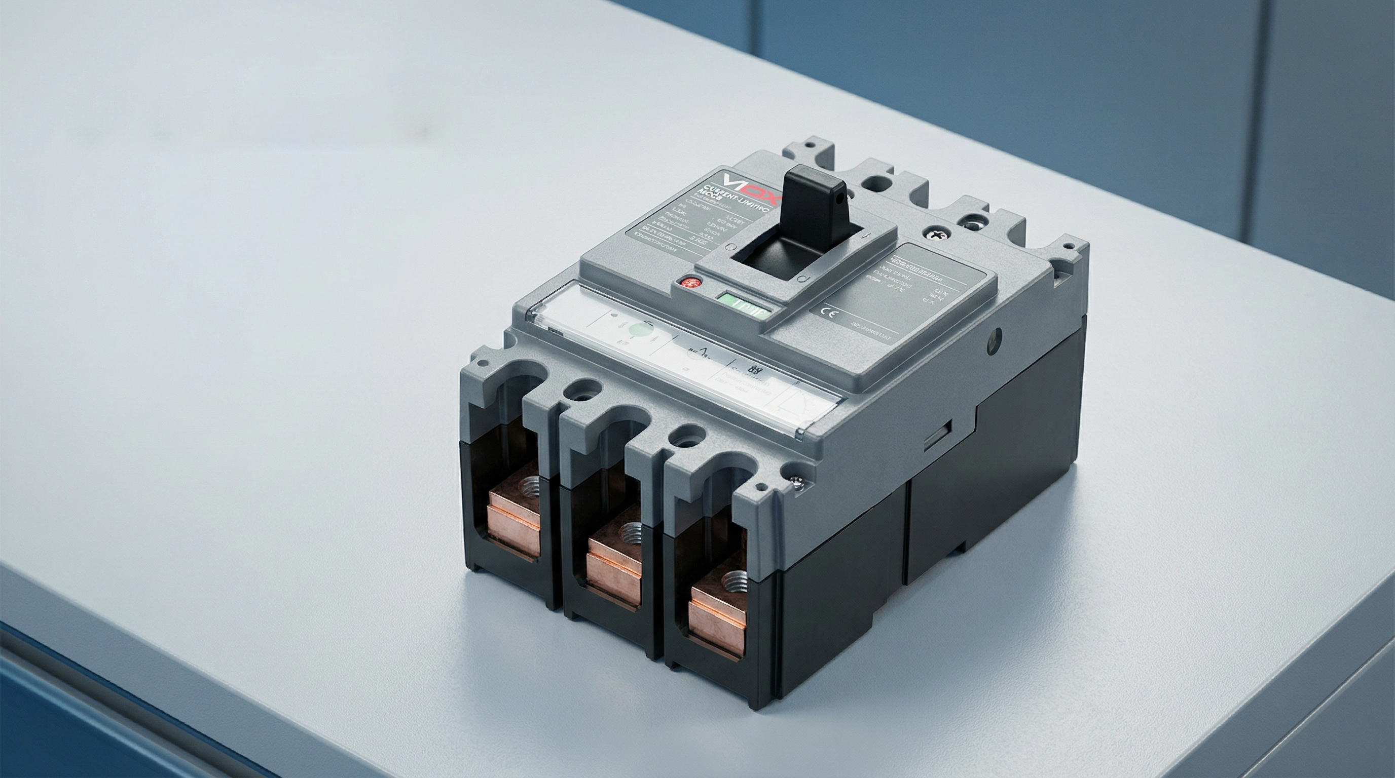
对于设计配电系统的电气工程师、选择保护设备的盘柜制造商,以及负责关键基础设施的设施管理人员而言,理解限流技术至关重要。本指南将阐述限流断路器的工作原理、定义其性能的关键技术规范,以及该技术在哪些场景下比标准电路保护方案更具关键优势。.
什么是限流断路器?
A current limiting circuit breaker is a protective device engineered to interrupt a short-circuit current before it reaches its maximum prospective peak value. This capability distinguishes it from conventional circuit breakers, which typically allow the fault current to reach its full peak before interrupting at a natural zero crossing.
When a short circuit occurs in an electrical system, the current begins rising at an extremely high rate—potentially reaching tens of thousands of amperes within milliseconds. A standard circuit breaker senses this fault condition and initiates its trip mechanism, but the interruption process takes time. During this brief interval, the fault current may reach its full prospective peak, releasing tremendous energy that stresses conductors, busbars, and downstream equipment.
Current limiting circuit breakers, by contrast, act with extraordinary speed. According to UL 489 (the North American standard for molded case circuit breakers), a circuit breaker qualifies as “current limiting” if it clears the fault in less than half a cycle—typically under 10 milliseconds. This rapid response introduces a high arc voltage that opposes the system voltage, effectively choking off the current flow and forcing the peak let-through current to a much lower value than the prospective fault current.
The result is dramatic: while a prospective fault current might be 50,000 amperes RMS symmetrical, a current-limiting breaker might limit the actual peak current to 15,000 amperes or less. This reduction in peak current and total fault energy protects downstream equipment from mechanical forces, thermal damage, and arc flash hazards that would otherwise occur.
How Current Limiting Circuit Breakers Work
The current-limiting capability of these circuit breakers results from a carefully engineered combination of mechanical design, electromagnetic physics, and arc management. The process unfolds in milliseconds through several coordinated mechanisms.
Electrodynamic Contact Separation
The first critical element is ultra-fast contact separation. When a high fault current flows through the breaker’s contacts, the enormous magnetic fields generated by this current create powerful electrodynamic forces. Current-limiting breakers are designed with contact configurations that harness these forces to assist separation—the contacts are arranged so the magnetic field creates a repulsive force that literally blows the contacts apart.
This “electrodynamic repulsion” means that higher fault currents actually accelerate contact separation. The breaker doesn’t rely solely on the mechanical force of the trip mechanism; the fault current itself contributes energy to open the contacts faster. This ensures extremely rapid contact separation—often within 1-2 milliseconds of fault initiation.
Arc Formation and Elongation
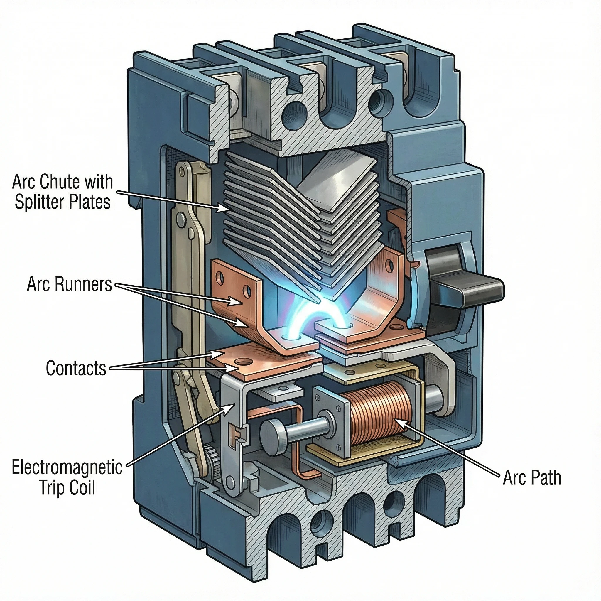
As the contacts separate at high speed, an electrical arc forms in the gap. Rather than being a problem to suppress, this arc becomes the primary tool for current limitation. The breaker’s internal geometry is designed to force this arc to move rapidly away from the contacts and into a specially designed arc chamber called an arc chute.
Magnetic fields generated by the current flow and the physical shape of the arc runners guide the arc upward into the arc chute. As the arc moves and stretches, its length increases dramatically. A longer arc requires higher voltage to sustain it, and this arc voltage opposes the system voltage driving the fault current.
Arc Commutation and Splitting
The arc chute contains a series of metal plates arranged in a specific configuration (often V-shaped), called arc splitters or arc dividers. As the arc is driven into the chute, it contacts these plates and “commutates”—transferring from the main arc path to the splitter plates.
This process effectively splits the single high-energy arc into multiple smaller arcs in series. Each small arc develops its own voltage drop. If the arc chute contains, for example, 20 splitter plates, the total arc voltage can reach many times the system voltage. When the cumulative arc voltage exceeds the system voltage, the current is forced to decrease rapidly.
Arc Cooling and Extinction
The metal splitter plates also serve as heat sinks, rapidly cooling the arcs. The plates increase the arc’s surface area and conduct heat away. Combined with surrounding air or arc-quenching gases, this cooling reduces the arc’s conductivity.
The interplay of high arc voltage (opposing current flow) and arc cooling (reducing conductivity) forces the current toward zero. The breaker extinguishes the arc and clears the fault—all within a fraction of a cycle, before the fault current reaches its prospective peak.
This entire sequence—from fault detection through contact separation, arc elongation, splitting, and extinction—occurs in under 10 milliseconds. The current is interrupted not at a natural zero crossing but forcibly, by creating conditions where the arc cannot be sustained.
Spesifikasi Teknikal Utama
Understanding current-limiting performance requires familiarity with three critical specifications that define how effectively a breaker limits fault current and protects downstream equipment.
Let-Through Current (Ip)
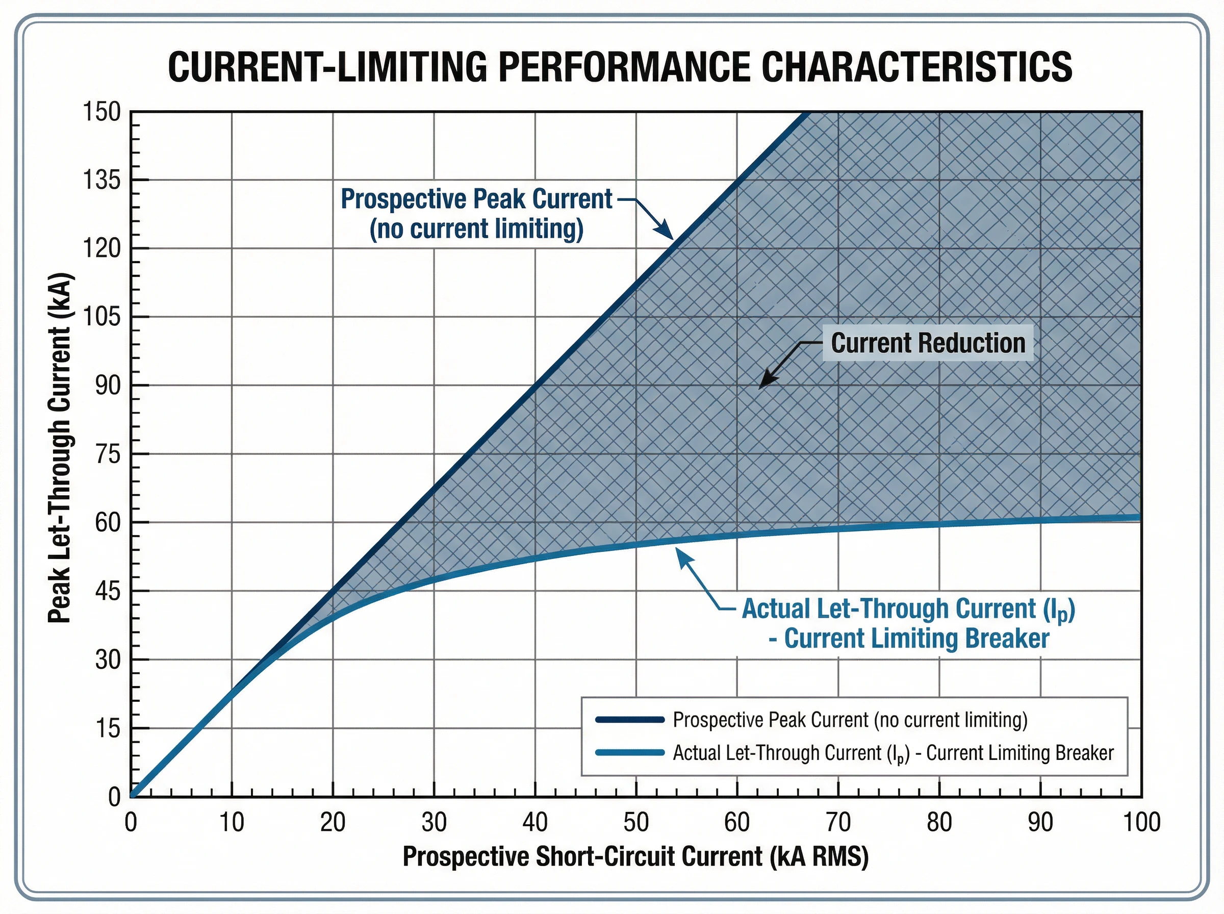
The let-through current (Ip) is the actual peak current that flows through the breaker during a fault, measured in amperes. This value represents the breaker’s current-limiting effectiveness: a lower Ip indicates better current limitation.
Manufacturers provide let-through current data in the form of characteristic curves. These graphs plot the peak let-through current (Ip) on the vertical axis against the prospective short-circuit current (RMS symmetrical amperes) on the horizontal axis. For any given prospective fault level at the installation point, the curve shows the maximum peak current that will actually flow.
For example, if the available fault current at a panelboard is 42,000 amperes RMS symmetrical, a current-limiting breaker might limit the actual peak current to just 18,000 amperes. This reduction from prospective to actual peak current protects busbars from bending, prevents conductor overheating, and reduces mechanical stress on all downstream components.
Thermal Stress (I²t)
The I²t value (pronounced “I-squared-t”), measured in ampere-squared seconds (A²s), quantifies the thermal energy let through by the breaker during fault clearing. It represents the integral of the current squared over the total clearing time.
This specification is critical for protecting cables and sensitive electronic equipment. The insulation of cables has a specific thermal withstand rating expressed as I²t. If the protective device lets through more thermal energy than the cable can withstand, the insulation will be damaged even if the cable doesn’t physically melt.
Current-limiting breakers dramatically reduce I²t compared to standard breakers. For the same prospective fault current, a current-limiting device might have an I²t value 50-80% lower than a conventional breaker. This reduced thermal stress prevents conductor damage, protects cable insulation, and extends equipment life.
Manufacturers provide I²t curves similar to let-through current curves, showing the maximum thermal energy as a function of prospective fault current. Some standards define energy-limiting classes for circuit breakers based on their I²t performance.
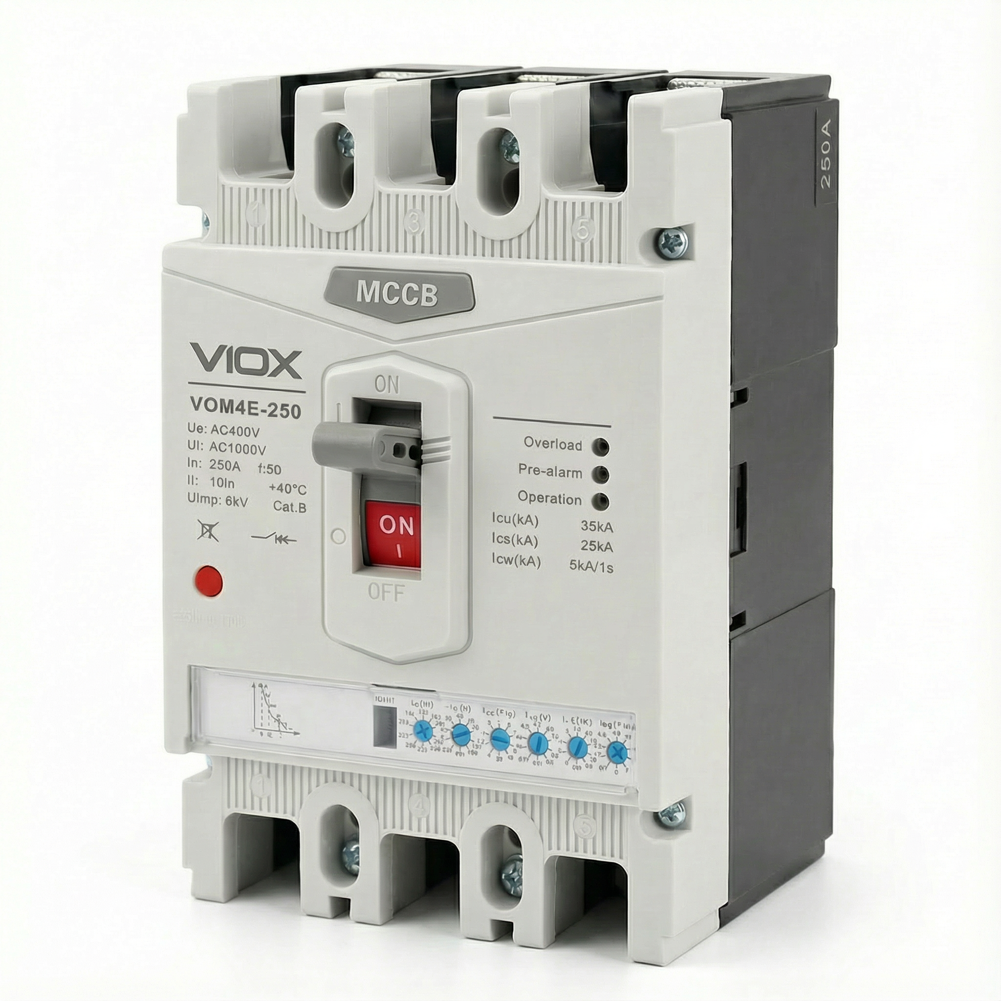
Breaking Capacity (Icu and Ics)
The kapasiti pecah defines the maximum fault current the breaker can safely interrupt. Two ratings are relevant under IEC 60947-2 (the international standard for low-voltage circuit breakers):
- Kapasiti Pecah Muktamad (Icu): The maximum fault current the breaker can interrupt without being destroyed. After interrupting a fault at Icu level, the breaker may not be suitable for continued service and might require replacement. This represents the breaker’s absolute upper limit.
- Kapasiti Pemecahan Perkhidmatan (Ic): The maximum fault current the breaker can interrupt multiple times while remaining fully functional and reliable for continued service. Ics is expressed as a percentage of Icu (typically 50%, 75%, or 100%). For critical applications requiring high reliability, breakers with Ics = 100% Icu are preferred.
The fundamental selection rule is straightforward: the breaker’s Icu must be equal to or greater than the prospective short-circuit current at the point of installation. Current-limiting breakers can achieve high breaking capacities (50kA, 85kA, or higher) in compact form factors because the current-limiting action itself reduces the energy the breaker must handle.
The Interrelationship of Specifications
These specifications work together to define protection performance. When a fault occurs up to the breaker’s Icu rating, the current-limiting action reduces both the peak current (Ip) and the total thermal energy (I²t) to values far below what the prospective fault would produce. This coordinated reduction in peak mechanical stress and thermal damage is what makes current-limiting breakers essential for protecting modern electrical systems with high available fault currents.
Standards and Compliance
Current-limiting circuit breakers are governed by rigorous international and regional standards that define performance requirements, testing procedures, and safety criteria.
IEC 60947-2: International Standard
IEC 60947-2 is the international standard for low-voltage circuit breakers used in industrial and commercial applications. This comprehensive standard establishes:
- Performance categories: The standard distinguishes between Category A breakers (no intentional short-circuit time delay) and Category B breakers (with short-time withstand capability). Most modern current-limiting MCCBs are Category A devices.
- Breaking capacity verification: IEC 60947-2 specifies rigorous test sequences to verify both ultimate breaking capacity (Icu) and service breaking capacity (Ics). These tests involve multiple making and breaking operations under specified fault conditions.
- Current-limiting performance: While the standard doesn’t mandate current limitation, it provides test procedures to verify and document let-through current and I²t performance for breakers claiming current-limiting capability.
- Coordination and selectivity: The standard establishes requirements for back-up protection (cascading), where a current-limiting breaker upstream protects a downstream breaker with lower breaking capacity than the prospective fault current at its location.
UL 489: North American Standard
UL 489 is the Underwriters Laboratories standard for molded case circuit breakers in North America. Key provisions include:
- Current-limiting definition: UL 489 specifies that a circuit breaker qualifies as “current limiting” if it clears a fault in less than half a cycle (typically under 10 milliseconds for 60 Hz systems).
- Let-through testing: The standard requires extensive testing to generate let-through current curves that show the actual peak current as a function of prospective fault current.
- Short-circuit ratings: UL 489 defines interrupting ratings (IR) and establishes test procedures to verify breaker performance at rated voltage and current levels.
Pematuhan dan Pensijilan
For electrical system designers and specifiers, standards compliance ensures:
- Verified performance: Certified breakers have undergone rigorous third-party testing to confirm their current-limiting capability and breaking capacity.
- Design confidence: Engineers can rely on published let-through curves and I²t data for equipment protection analysis and arc flash calculations.
- Regulatory acceptance: Standards-compliant breakers meet electrical code requirements in their respective markets (IEC zones or North American installations).
VIOX current-limiting circuit breakers are designed and tested to meet both IEC 60947-2 and UL 489 requirements, ensuring global applicability and verified protection performance.
Aplikasi dan Kes Penggunaan
Current-limiting circuit breakers deliver critical benefits in electrical systems where high available fault currents threaten equipment integrity and personnel safety.
Data Centers and Critical IT Infrastructure
Modern data centers face extraordinary fault current challenges. High-density server racks, powerful UPS systems, and multiple utility feeds create available fault currents that can exceed 65kA or more. Current-limiting breakers are essential in these environments:
- IT equipment protection: Servers, storage arrays, and networking gear contain sensitive electronics vulnerable to even brief overcurrent events. Current-limiting breakers reduce the fault energy to levels that prevent component damage.
- Penyelarasan terpilih: Data center reliability depends on isolating faults without cascading outages. Current-limiting breakers facilitate coordination between upstream and downstream protection, ensuring only the affected circuit trips.
- Arc flash mitigation: Maintenance personnel work on energized equipment regularly. By reducing peak fault current and clearing time, current-limiting breakers dramatically lower arc flash incident energy, improving worker safety and potentially reducing PPE requirements.
- Compact installations: Current-limiting technology enables high breaking capacity (50kA-100kA) in compact MCCBs, supporting dense power distribution without requiring oversized switchgear.
Industrial Manufacturing Facilities
Industrial plants with large motors, transformers, and extensive distribution networks face fault currents that can damage production equipment:
- Pusat kawalan motor: Protecting motor starters, variable frequency drives, and control electronics from fault current stress. Current-limiting breakers prevent damage to expensive drive electronics and ensure production continuity.
- High-capacity feeders: Where multiple power sources or large transformers create fault currents exceeding 50kA, current-limiting breakers provide protection without requiring expensive high-interrupting-capacity switchgear throughout the system.
- Perlindungan peralatan: Busbars, cable trays, and panel components have mechanical strength limits. Current-limiting breakers reduce the magnetic forces during faults, preventing physical damage to distribution infrastructure.
Commercial Buildings with High Power Density
Office towers, hospitals, and retail centers increasingly deploy high-power systems:
- Main and sub-main distribution: Current-limiting breakers on main service entrances and distribution boards protect against utility-supplied fault currents while enabling effective downstream coordination.
- Sistem kuasa kecemasan: Generator and transfer switch protection where multiple sources increase available fault current.
- Renovation and expansion: Adding capacity to existing buildings often increases fault current levels. Current-limiting breakers can sometimes eliminate the need for complete system upgrades by providing adequate protection within existing infrastructure ratings.
Cascading Protection (Back-Up Protection)
One of the most valuable applications is enabling cascading or series rating. A current-limiting breaker installed upstream can protect downstream breakers with lower breaking capacity than the prospective fault current at their location. This allows:
- Pengoptimuman kos: Using less expensive, lower-rated breakers downstream while maintaining full protection.
- Simplified specification: Standardizing on common breaker types throughout the facility while the current-limiting main breaker provides system-wide protection.
- System flexibility: Menambah litar atau beban tanpa semestinya menaik taraf semua peranti perlindungan hiliran.
Had Semasa lwn Pemutus Litar Standard
Memahami perbezaan antara pemutus litar had semasa dan standard menjelaskan masa setiap teknologi sesuai.
Kaedah Gangguan
Pemutus Standard: Pemutus litar konvensional mengesan kerosakan dan memulakan mekanisme perjalanan, tetapi membenarkan arus kerosakan meningkat kepada nilai puncak prospektifnya. Gangguan berlaku pada atau berhampiran lintasan sifar arus semula jadi, biasanya selepas 0.5 hingga 1.5 kitaran (8-25 milisaat pada 60 Hz). Dalam masa ini, arus kerosakan penuh menekankan sistem.
Pemutus Had Semasa: Peranti ini bertindak dalam milisaat untuk mengganggu arus secara paksa sebelum ia mencapai puncak prospektifnya. Melalui pemisahan sentuhan elektrodinamik dan pembentukan voltan arka, mereka membersihkan kerosakan dalam masa kurang daripada separuh kitaran (di bawah 10 milisaat), mengurangkan secara mendadak kedua-dua arus puncak dan jumlah tenaga kerosakan.
Arus Puncak dan Tekanan Mekanikal
Pemutus Standard: Arus kerosakan prospektif penuh mengalir, mewujudkan daya magnet maksimum. Untuk kerosakan prospektif 50kA, 50kA penuh (puncak asimetri 70kA) menjana tekanan mekanikal yang besar pada bar bas, terminal dan sambungan.
Pemutus Had Semasa: Arus lepas jauh berkurangan. Untuk kerosakan prospektif 50kA yang sama, pemutus had semasa mungkin mengehadkan puncak sebenar kepada 15-20kA, mengurangkan daya magnet sebanyak 60-70%.
Tenaga Haba (I²t)
Pemutus Standard: Masa penjelasan yang lebih lama dan arus puncak yang lebih tinggi menghasilkan pelepasan tenaga haba yang besar. Kabel, bar bas dan sambungan menyerap haba yang ketara, yang berpotensi merosakkan penebat.
Pemutus Had Semasa: Arus puncak yang dikurangkan dan penjelasan ultra pantas menurunkan nilai I²t secara mendadak, selalunya sebanyak 50-80%. Ini melindungi penebat kabel, menghalang penyepuhlindapan konduktor dan melindungi elektronik sensitif daripada tekanan haba.
Tenaga Insiden Kilat Arka
Pemutus Standard: Arus kerosakan yang lebih tinggi dan masa penjelasan yang lebih lama meningkatkan tenaga insiden kilat arka, memerlukan PPE peringkat lebih tinggi dan mewujudkan bahaya keselamatan yang lebih besar untuk kakitangan penyelenggaraan.
Pemutus Had Semasa: Magnitud dan tempoh arus kerosakan yang dikurangkan mengurangkan tenaga kilat arka dengan ketara. Ini boleh menurunkan sempadan kilat arka, mengurangkan keperluan PPE dan meningkatkan keselamatan elektrik keseluruhan.
Tukar Ganti Kos dan Kerumitan
Pemutus Standard: Secara amnya kurang mahal setiap unit. Sesuai untuk aplikasi di mana arus kerosakan adalah sederhana dan penarafan peralatan melebihi tahap kerosakan yang tersedia dengan secukupnya.
Pemutus Had Semasa: Kos permulaan yang lebih tinggi, tetapi boleh mengurangkan jumlah kos sistem dengan:
- Membenarkan komponen hiliran tugas yang lebih ringan
- Membolehkan perlindungan lata dengan pemutus berkadar lebih rendah
- Mengurangkan keperluan pengukuhan panel
- Melindungi peralatan mahal daripada kerosakan
- Menurunkan kos pengurangan kilat arka
Bila Memilih Setiap Jenis
Pilih Pemutus Standard apabila:
- Arus kerosakan yang tersedia jauh di bawah penarafan litar pintas sistem
- Kekangan belanjawan adalah yang terpenting dan tahap kerosakan tidak mewajarkan perlindungan had semasa
- Penyelarasan boleh dicapai tanpa had semasa
Pilih Pemutus Had Semasa apabila:
- Arus kerosakan yang tersedia melebihi 20-25kA
- Melindungi peralatan elektronik sensitif (pusat data, sistem kawalan)
- Mencari pengurangan bahaya kilat arka
- Membolehkan perlindungan lata untuk mengurangkan kos
- Pengembangan kemudahan telah meningkatkan tahap kerosakan melebihi penarafan peralatan asal
Kriteria Pemilihan
Memilih pemutus litar had semasa yang betul memerlukan penilaian beberapa faktor teknikal dan aplikasi.
Kira Arus Kerosakan Tersedia
Langkah pertama ialah menentukan arus litar pintas prospektif pada titik pemasangan. Ini memerlukan:
- Kapasiti dan impedans pengubah utiliti
- Panjang dan saiz konduktor
- Impedans komponen pengagihan
- Sumbangan daripada motor dan penjana
Banyak utiliti menyediakan data arus kerosakan, atau jurutera elektrik bertauliah boleh melakukan pengiraan litar pintas menggunakan kaedah standard industri (IEC 60909 atau piawaian IEEE). Kapasiti pemecahan muktamad pemutus (Icu) mesti memenuhi atau melebihi arus kerosakan yang dikira ini.
Nilaikan Keperluan Perlindungan Peralatan
Pertimbangkan apa yang memerlukan perlindungan:
- elektronik sensitif: Pusat data, sistem kawalan dan peralatan telekomunikasi mendapat manfaat yang ketara daripada pengurangan arus lepas dan I²t.
- Penarafan bar bas dan konduktor: Jika arus kerosakan menghampiri atau melebihi penarafan tahan litar pintas bar bas, kabel atau komponen panel, had semasa menjadi penting.
- Peralatan sedia ada: When expanding facilities, current-limiting breakers can sometimes protect existing infrastructure without requiring complete replacement.
Assess Arc Flash Hazard Mitigation Needs
If arc flash studies indicate high incident energy levels requiring extensive PPE or creating unacceptable worker hazards, current-limiting breakers can significantly reduce arc flash energy. Review arc flash calculations to determine if current limitation would lower the hazard category and improve safety.
Consider Coordination Requirements
Selective coordination—ensuring only the breaker nearest the fault trips—is critical in many applications:
- Cascading protection: If downstream breakers have breaking capacities lower than available fault current, a current-limiting breaker upstream can provide back-up protection.
- Critical loads: Data centers, hospitals, and industrial processes require fault isolation without unnecessary outages. Current-limiting breakers facilitate coordination by reducing let-through energy.
Review Let-Through Current Curves
Manufacturers provide let-through current (Ip) and I²t curves for their current-limiting breakers. Compare these curves against:
- Equipment withstand ratings
- Cable I²t limits
- Arc flash energy reduction targets
- Coordination requirements with downstream devices
Verify Standards Compliance
Ensure the breaker meets applicable standards:
- IEC 60947-2 for international/industrial applications
- UL 489 for North American installations
- Local electrical codes and certification requirements
Kesimpulan
Current-limiting circuit breakers represent a critical advancement in electrical protection technology, addressing the fundamental challenge of high fault currents in modern power systems. By interrupting faults in milliseconds and dramatically reducing peak let-through current and thermal stress, these devices protect expensive equipment, improve personnel safety, and enable more flexible system designs.
For electrical engineers and facility managers working with high-power distribution systems—particularly data centers, industrial facilities, and commercial buildings with fault currents exceeding 25kA—current-limiting technology delivers measurable benefits in equipment protection, arc flash mitigation, and coordination flexibility. The key specifications (let-through current Ip, thermal stress I²t, and breaking capacity Icu) provide the engineering data needed to verify protection performance and ensure safe, reliable operation.
VIOX Electric manufactures current-limiting circuit breakers engineered to IEC 60947-2 and UL 489 standards, offering breaking capacities from 35kA to 100kA and comprehensive let-through performance curves. For technical specifications, application guidance, or to discuss your specific protection requirements, contact VIOX’s engineering team.
Protect your critical infrastructure with proven current-limiting technology. Hubungi VIOX Electric to discuss your circuit protection needs.
