
Der Anruf um 2 Uhr morgens, den jeder Betriebsingenieur fürchtet

Sie haben die Schalttafeln Ihrer Anlage sorgfältig entworfen und gewartet. Jeder Stromkreis ist dokumentiert, jede Sicherung ist korrekt auf ihre Last ausgelegt, und Ihr vorbeugender Wartungsplan ist straff. Dann klingelt Ihr Telefon um 2 Uhr morgens. Produktionslinie 3 ist ausgefallen. Schon wieder.
Sie eilen in die Produktionshalle, und die Diagnose ist bekannt: eine durchgebrannte Sicherung im Motorstarterkreis. Nun beginnt der operative Albtraum. Ihr Wartungstechniker muss eine Ersatzsicherung der Klasse CC mit 20 A im Lager finden (hoffentlich ist sie vorrätig), die LOTO-Verfahren befolgen, um die Tafel sicher spannungsfrei zu schalten, die defekte Sicherung austauschen, wieder einschalten und testen. Wenn alles glatt läuft, haben Sie mindestens 45 Minuten Ausfallzeit. Aber hier ist die eigentliche Frage, die Sie nachts wach halten sollte: Warum verwenden wir immer noch eine Schutzmethode, die jedes Mal, wenn sie ihre Aufgabe erfüllt, eine vollständige Abschaltung und den Austausch von Teilen erfordert?
Dies ist kein Wartungsproblem. Es ist ein Technologieproblem – und es gibt eine Lösung.
Warum Sicherungen Ihre Betriebszeit immer wieder sabotieren
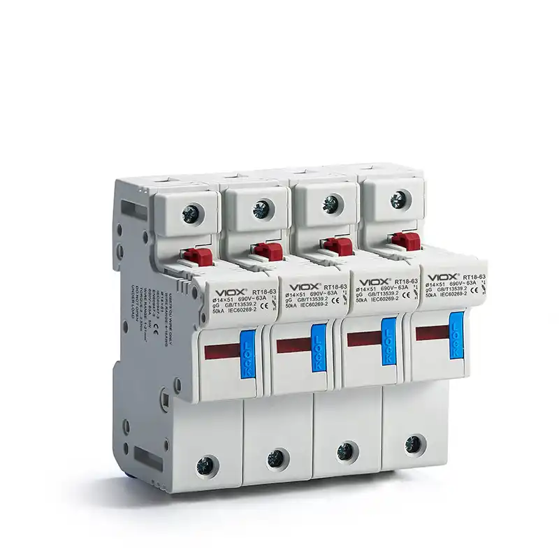

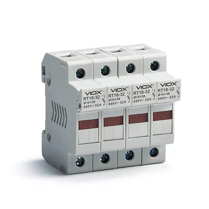
VIOX-SICHERUNG
Um zu verstehen, warum Sicherungen operative Reibungsverluste verursachen, müssen Sie sich ansehen, wie sie tatsächlich funktionieren. Eine Sicherung ist im Wesentlichen eine kontrollierte Schwachstelle in Ihrem Stromkreis. In diesem kleinen Keramik- oder Glaskörper befindet sich ein dünner Metalldraht – stellen Sie ihn sich als einen absichtlich zerbrechlichen Draht vor. Wenn der Strom die Nennleistung der Sicherung überschreitet, schmilzt dieser Draht durch Widerstandserwärmung. Der Stromkreis öffnet sich und schützt nachgeschaltete Geräte vor Schäden.
Das Problem? Dieser Draht ist nun für immer verschwunden.
Im Gegensatz zu fast allen anderen Komponenten in Ihrem Schaltschrank ist eine Sicherung für den einmaligen Gebrauch konzipiert. Sie ist eine “opferbereite” Schutzvorrichtung. Dies war vollkommen sinnvoll, als Sicherungen vor über 100 Jahren erfunden wurden – sie waren einfach, zuverlässig und billig. Aber in einer modernen Industrieanlage, in der jede Minute Ausfallzeit Hunderte oder Tausende von Dollar an Produktionsausfällen kostet, kostet Sie diese Designphilosophie Geld.
Betrachten Sie die tatsächlichen Kosten eines einzelnen Vorfalls mit einer durchgebrannten Sicherung:
- Direkte Kosten: Ersatzsicherung ($5-25), Technikerarbeit (0,5-2 Stunden bei $50-100/Std.)
- Indirekte Kosten: Produktionsausfall während der Ausfallzeit, mögliche Eilgebühren, wenn kein Ersatzteil vorrätig ist, Fehlersuche, wenn die falsche Sicherung eingebaut ist
- Versteckte Kosten: Sicherheitsrisiko beim Austausch, Lagerhaltungskosten für Ersatzsicherungen jeder Größe
专业提示: Die meisten Ingenieure berechnen nur die Kosten für das Ersatzteil, wenn sie Sicherungen mit Schutzschaltern vergleichen. Aber ein einzelner Vorfall mit einer durchgebrannten Sicherung in einer Produktionslinie kann insgesamt $500-$2.000 kosten, wenn man die Arbeitskosten und den Produktionsausfall berücksichtigt. Wenn Sie Sicherungen mehr als 2-3 Mal pro Jahr in einem Stromkreis austauschen, amortisieren sich Schutzschalter innerhalb von 12-18 Monaten.
Der Vorteil von Schutzschaltern: Schutz ohne Opfer


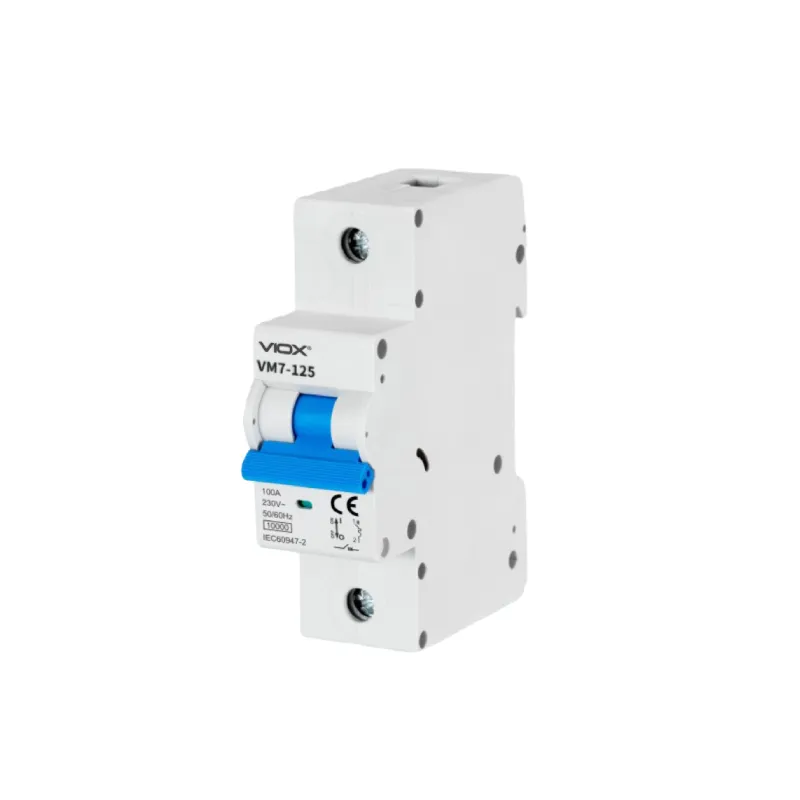
Schutzschalter beheben den grundlegenden Fehler von Sicherungen, indem sie einen völlig anderen Schutzmechanismus verwenden. Anstelle eines opferbereiten Elements verwenden Schutzschalter entweder Bimetallstreifen (thermischer Schutz) oder elektromagnetische Spulen (magnetischer Schutz) – oft beides in Kombination –, um Überstrombedingungen zu erkennen.
Wenn eine Überlast auftritt, löst der interne Mechanismus des Schutzschalters aus und unterbricht den Stromfluss genau wie eine Sicherung. Aber hier ist der entscheidende Unterschied: Die Sensorelemente und Kontakte des Schutzschalters bleiben intakt und funktionsfähig. Um die Stromversorgung wiederherzustellen, schalten Sie den Schalter des Schutzschalters einfach wieder in die “Ein”-Position. Keine Teile zu beschaffen. Kein Lager zu verwalten. Keine erweiterten LOTO-Verfahren.
Für Schaltschrankanwendungen arbeiten Sie hauptsächlich mit zwei Arten von UL-gelisteten Schutzschaltern:
- UL1077 Zusätzliche Schutzschalter: Geringere Kosten, typischerweise für Steuerstromkreise und kleinere Abzweigstromkreise innerhalb von Schalttafeln verwendet
- UL489 Leitungsschutzschalter: Höheres Ausschaltvermögen, verwendet für Abzweigstromkreisschutz und größere Lasten
Beide bieten einen Überstromschutz, der dem von Sicherungen entspricht, und bieten gleichzeitig eine Rücksetzfunktion. Moderne Schutzschalter integrieren auch fortschrittliche Sicherheitsfunktionen, die Sicherungen einfach nicht bieten können, einschließlich Fehlerlichtbogenerkennung, Erdschlussschutz und einstellbare Auslösekennlinien für bestimmte Anwendungen.
要点总结: Allein der Komfortfaktor – Rücksetzen statt Austauschen – macht Schutzschalter für die meisten industriellen Anwendungen überlegen. Aber der eigentliche Wert liegt im Betrieb: reduzierte Ausfallzeiten, beseitigte Lagerhaltungsprobleme und niedrigere langfristige Wartungskosten.
Die 5-Schritte-Methode des Ingenieurs für die Migration von Sicherungen zu Schutzschaltern

Der Wechsel von Sicherungen zu Schutzschaltern in Ihren Schalttafeln ist kein einfacher Eins-zu-Eins-Austausch. Wenn Sie es falsch machen, kommt es zu Fehlauslösungen, unzureichendem Schutz oder sogar zu Sicherheitsrisiken. Befolgen Sie diesen systematischen Ansatz, um den Erfolg sicherzustellen.
Schritt 1: Überprüfen Sie Ihr System und planen Sie die Arbeit
Bevor Sie auch nur einen einzigen Draht berühren, dokumentieren Sie Ihre bestehende Einrichtung gründlich. Dies ist nicht nur eine gute Praxis – in den meisten Gerichtsbarkeiten ist es gesetzlich vorgeschrieben.
Was zu dokumentieren ist:
- Aktuelle Sicherungsnennwerte für jeden Stromkreis (Stromstärke und Sicherungsklasse)
- Stromkreislasten (Motoren, Beleuchtung, Steuerstromkreise usw.)
- Drahtgrößen und -typen für die Eingangs- und Ausgangsseite
- Schalttafel-Layout und verfügbarer Platz für die DIN-Schienenmontage
- Alle Motorleistungsschilder mit FLA, PS, Spannung und Servicefaktor
Kritischer Planungsschritt: Überprüfen Sie Ihre lokalen Bauvorschriften und NEC-Anforderungen. Viele Gerichtsbarkeiten verlangen Genehmigungen und Inspektionen (durch die zuständige Behörde oder AHJ), bevor die Schaltschrankverkabelung geändert wird. Planen Sie dafür Zeit in Ihrem Projektplan ein.
专业提示: Verwenden Sie ein einfaches Nummern- oder Buchstabensystem, um sowohl die Eingangs- als auch die Ausgangsdrähte für jeden Stromkreis zu markieren, bevor Sie mit dem Entfernen beginnen. Schreiben Sie diese auf Drahtmarkierer oder Klebeband. Dieser 2-Minuten-Schritt während der Dokumentation spart Ihnen Stunden bei der Fehlersuche, wenn Drähte während der Installation verwechselt werden.
Schritt 2: Wählen Sie die richtigen Schutzschalter aus (hier machen die meisten Ingenieure Fehler)
Hier ist der Fehler, der 90% der Probleme nach der Installation verursacht: Ingenieure gehen davon aus, dass sie einfach die Sicherungsstromstärke an die Schutzschalterstromstärke anpassen können. Eine 30-A-Sicherung wird durch einen 30-A-Schutzschalter ersetzt, richtig? Falsch.
Sicherungen und Schutzschalter haben unterschiedliche Zeit-Strom-Kennlinien. Sie reagieren unterschiedlich auf Überlastungen und Kurzschlüsse. Dies ist besonders wichtig für Motorstromkreise, bei denen der Einschaltstrom beim Anfahren das 6-8-fache des Volllaststroms betragen kann.
Befolgen Sie für Motorabzweigstromkreise diesen Prozess:
- Bestimmen Sie die Motorspezifikationen: Ermitteln Sie den Volllaststrom (FLA), die Leistung und die Versorgungsspannung des Motors vom Leistungsschild
- Berechnen Sie die Einschaltstromberücksichtigung: Der Motoranlaufstrom ist nicht kontinuierlich, daher müssen Überlastschutzvorrichtungen diese vorübergehende Stoßbelastung tolerieren
- Wenden Sie NEC-Artikel 430 an: Verwenden Sie NEC-Tabelle 430.52, um die maximale Nennleistung für Kurzschluss- und Erdschlussschutzvorrichtungen für Abzweigstromkreise zu bestimmen
- Wählen Sie den Schutzschaltertyp und die Auslösekennlinie aus:
- Inverse Zeitschutzschalter (B-, C- oder D-Kennlinie) für Motoranwendungen
- C-Kennlinien-Schutzschalter bewältigen typische Motorlasten
- D-Kennlinien-Schutzschalter für Anwendungen mit hohem Einschaltstrom wie Transformatoren
Wichtiger Unterschied: Der Motorüberlastschutz (typischerweise auf 115-125% des FLA ausgelegt) ist vom Überstromschutz des Abzweigstromkreises getrennt. Der Schutzschalter, den Sie installieren, bietet Kurzschluss- und Erdschlussschutz – er ist nicht dasselbe wie das Überlastrelais in Ihrem Motorstarter.
Profi-Tipp für Motorstromkreise: Eine 30-A-Sicherung der Klasse CC, die einen 10-PS-Motor mit 460 V schützt, benötigt aufgrund unterschiedlicher Auslösecharakteristiken möglicherweise nur einen 20-A-Schutzschalter. Berechnen Sie immer anhand von NEC-Artikel 430 und Motornennstromtabellen neu, anstatt einen direkten Stromstärkenaustausch vorzunehmen. Im Zweifelsfall wenden Sie sich an den technischen Support des Schutzschalterherstellers – er kann Ihnen bei der Auswahl der richtigen Auslösekennlinie und Nennleistung helfen.
Für Nicht-Motorstromkreise (Beleuchtung, Steuerstrom, ohmsche Lasten) ist die Dimensionierung einfacher. Der Schutzschalter sollte für 125% Dauerlasten und 100% Nicht-Dauerlasten ausgelegt sein, wobei die Drahtstrombelastbarkeit der begrenzende Faktor gemäß NEC-Artikel 210 ist.
Schritt 3: Bereiten Sie sich auf eine sichere Installation vor
Elektroarbeiten in Schalttafeln bergen erhebliche Risiken. Bevor Sie mit den physischen Arbeiten beginnen, stellen Sie sicher, dass Sie alles für eine sichere und effiziente Installation vorbereitet haben.
Erforderliche Sicherheitsverfahren:
- Lock-Out/Tag-Out (LOTO): Schalten Sie die Schalttafel am Haupttrennschalter spannungsfrei. Verriegeln Sie den Trennschalter in der “Aus”-Position und kennzeichnen Sie ihn entsprechend
- Nullspannung prüfen: Verwenden Sie ein Digitalvoltmeter oder einen berührungslosen Spannungsdetektor, um sicherzustellen, dass an den netzseitigen Anschlüssen keine Spannung anliegt.
- Persönliche Schutzausrüstung (PSA): Tragen Sie mindestens eine Schutzbrille und isolierte Handschuhe. Je nach den Sicherheitsstandards Ihrer Einrichtung kann arc-feste Kleidung erforderlich sein.
专业提示: Schaltschränke können “fremde” Stromquellen haben – eingehende Stromversorgung von externen Quellen, die den Haupttrennschalter umgehen. Achten Sie auf orangefarbene oder gelbe Kabel (gemäß NEC-Standards weisen diese Farben auf alternative Stromquellen hin). Immer mit einem Messgerät überprüfen, niemals annehmen.
Checkliste für Werkzeuge und Materialien:
- DIN-Schiene (35 mm ist Standard), falls noch nicht im Schaltschrank installiert
- DIN-Schienen-Befestigungsmaterial (Schrauben, keine gewindeschneidenden Schrauben)
- Geeignete Schutzschalter (UL1077 oder UL489, wie angegeben)
- Drahtmarkierer oder Etiketten zur Stromkreisidentifizierung
- Isolierte Schraubendreher (Kreuzschlitz, Schlitz, Torx, Vierkant je nach Bedarf)
- Abisolierzangen für verschiedene Drahtstärken
- Digitalvoltmeter oder berührungsloser Spannungsdetektor
- Installationsanweisungen und Drehmomentangaben des Herstellers
- Drahtverlängerungen, wenn vorhandene Netz- oder Lastleitungen zu kurz sind
Schritt 4: Durchführung des physischen Austauschs
Nachdem die Planung abgeschlossen und die Sicherheitsmaßnahmen getroffen wurden, sind Sie bereit für die eigentliche Arbeit. Befolgen Sie diese Reihenfolge, um die Organisation aufrechtzuerhalten und Fehler zu vermeiden.
Entfernung der vorhandenen Sicherungsblöcke:
- Ein letztes Mal dokumentieren: Machen Sie Fotos von der Verdrahtung des Sicherungsblocks vor dem Entfernen. Diese dienen als Referenz, falls Fragen auftauchen.
- Stromkreise deutlich kennzeichnen: Beschriften Sie sowohl die Netz- als auch die Lastleitungen mit übereinstimmenden Stromkreiskennungen (z. B. “Stromkreis 1A” sowohl auf der Netz- als auch auf der Lastseite).
- Sicherungsnennwerte notieren: Notieren Sie die Sicherungsgröße für jeden Stromkreis – dies hilft bei der Validierung Ihrer Schutzschalterdimensionierung.
- Sicherungsblöcke entfernen: Demontieren Sie die Sicherungsblöcke von der Rückwand und halten Sie die Drähte organisiert.
Installation von Schutzschaltern:
- DIN-Schiene montieren: Wenn Ihr Schaltschrank noch keine DIN-Schiene hat, installieren Sie diese an einem geeigneten Ort. Stellen Sie gemäß den NEC-Abstandsanforderungen einen ausreichenden Abstand zu anderen Komponenten sicher.
- Schutzschalter auf die Schiene schnappen: Schutzschalter, die für die DIN-Schienenmontage ausgelegt sind, rasten einfach ein. Stellen Sie sicher, dass sie sicher sind.
- Drähte vorbereiten: Isolieren Sie die Drahtisolierung auf die in den Anweisungen des Schutzschalterherstellers angegebene Länge ab (typischerweise 10-12 mm). Wenn die Drähte für die neuen Schutzschalterpositionen zu kurz sind, verlängern Sie sie mit geeigneten Spleißmethoden oder Ersatzdrähten.
- Netzseitige Stromversorgung anschließen: Schließen Sie die eingehende Stromversorgung an die Netzanschlüsse der Schutzschalter an. Befolgen Sie die Drehmomentangaben des Herstellers genau – ein zu festes Anziehen kann die Anschlüsse beschädigen, ein zu lockeres Anziehen erzeugt Widerstand und Wärme.
- Lastseitige Verdrahtung anschließen: Schließen Sie die Lastleitungen an die Lastanschlüsse an und beachten Sie auch hier die korrekten Drehmomentwerte.
- Erdungsverbindungen überprüfen: Stellen Sie sicher, dass alle Erdungsdrähte (blankes Kupfer, grün oder grün mit gelbem Streifen in US-Installationen) ordnungsgemäß abgeschlossen sind.
Wichtiger Installationshinweis: Befolgen Sie immer die Installationsanweisungen des Schutzschalterherstellers für Drahtabisolierlänge, Klemmenanzugsmomente und Montageausrichtung. Diese variieren je nach Hersteller und Modell. Die Verwendung des falschen Drehmoments ist einer der häufigsten Installationsfehler und kann zu Überhitzung, Lichtbögen oder Verbindungsfehlern führen.
Schritt 5: Testen, Verifizieren und Inbetriebnehmen
Schalten Sie einen Schaltschrank niemals wieder ein und gehen Sie davon aus, dass alles funktioniert. Systematische Tests verhindern Geräteschäden und gefährliche Situationen.
Überprüfungen vor der Inbetriebnahme:
- Sichtprüfung: Stellen Sie sicher, dass alle Verbindungen fest und ordnungsgemäß abgeschlossen sind.
- Drehmomentprüfung: Überprüfen Sie nochmals, ob alle Anschlüsse gemäß den Spezifikationen angezogen sind.
- Zugtest: Ziehen Sie vorsichtig an jedem Draht, um die mechanische Verbindung zu überprüfen.
- Komponentenpositionsprüfung: Stellen Sie sicher, dass sich alle Schutzschalter in der “Aus”-Position befinden, bevor Sie Strom anlegen.
Einschaltsequenz:
- LOTO-Vorrichtungen entfernen: Entfernen Sie gemäß den Verfahren Ihrer Einrichtung Schlösser und Etiketten vom Haupttrennschalter.
- Strom an den Schaltschrank anlegen: Schließen Sie den Haupttrennschalter, um den Schaltschrank mit Strom zu versorgen.
- Steuerspannung überprüfen: Schalten Sie die Steuerspannungskreise ein und überprüfen Sie die korrekte Spannung.
- Stromkreise einzeln einschalten: Schalten Sie jeweils einen Schutzschalter ein und überprüfen Sie den ordnungsgemäßen Betrieb.
- Belastungstests: Überprüfen Sie bei jedem eingeschalteten Stromkreis, ob die Lasten ordnungsgemäß funktionieren.
- Motortest: Durchlaufen Sie bei Motorkreisen Start-Stopp-Sequenzen, um zu bestätigen, dass die Schutzschalter den Einschaltstrom ordnungsgemäß verarbeiten.
专业提示: Wenn ein Schutzschalter sofort nach dem Schließen auslöst, setzen Sie ihn nicht immer wieder zurück. Dies deutet auf ein echtes Problem hin – entweder einen Kurzschluss in der Verkabelung, einen tatsächlichen Überlastzustand oder einen falsch dimensionierten Schutzschalter. Beheben Sie das Problem, bevor Sie mehrere Rücksetzungen versuchen.
Abschließender Schritt der Inbetriebnahme: Sobald alle Stromkreise betriebsbereit sind, belasten Sie das System und überprüfen Sie die Leistung unter normalen Betriebsbedingungen. Überwachen Sie das Panel während der ersten Betriebsstunden, um sicherzustellen, dass es an den Verbindungen zu keiner Temperaturerhöhung oder zu Fehlauslösungen kommt.
Wenn Schutzschalter immer wieder auslösen: Fehlersuche jenseits des Schutzschalters
Sie haben die Installation abgeschlossen, aber ein Schutzschalter löst während des Betriebs immer wieder aus. Bevor Sie davon ausgehen, dass der Schutzschalter defekt oder falsch dimensioniert ist, schließen Sie systematisch andere Ursachen aus:
- Überprüfen Sie die angeschlossenen Geräte: Ein defekter Motor, ein Kurzschluss in der angeschlossenen Verkabelung oder eine tatsächliche Überlastung lösen einen ordnungsgemäß funktionierenden Schutzschalter aus. Trennen Sie die Lasten einzeln ab und testen Sie, um problematische Geräte zu isolieren.
- Überprüfen Sie die Drahtverbindungen: Lose Verbindungen erzeugen Widerstand, Wärme und Spannungsabfall. Dies kann dazu führen, dass Motoren übermäßigen Strom ziehen. Überprüfen Sie alle Anschlussdrehmomente erneut.
- Bewerten Sie die Umgebungstemperatur: Schutzschalter sind für bestimmte Umgebungstemperaturen ausgelegt (typischerweise 40 °C). Wenn sich Ihr Panel in einer heißen Umgebung befindet, können thermische Schutzelemente bei niedrigeren Strömen auslösen. Möglicherweise müssen Sie den Schutzschalter reduzieren oder die Panelkühlung verbessern.
- Überprüfen Sie die richtige Auswahl des Schutzschalters: Wenn es beim Anlassen von Motoren zu Fehlauslösungen kommt, benötigen Sie möglicherweise einen Schutzschalter mit einer höheren magnetischen Auslöseeinstellung (D-Kurve anstelle von C-Kurve) oder Sie müssen gemäß NEC-Tabelle 430.52 eine größere Dimensionierung vornehmen.
Der ROI, der das Management “Ja” sagen lässt”
Wenn Sie dem Management ein Projekt zur Aufrüstung von Sicherungen auf Schutzschalter vorstellen, konzentrieren Sie sich auf quantifizierbare betriebliche Vorteile und nicht nur darauf, dass es sich um “bessere Technologie” handelt.”
Beispielhafte ROI-Berechnung für ein typisches Bedienfeld mit 10 Stromkreisen:
Aktueller Zustand (Sicherungen):
- Durchschnittliche Anzahl von Sicherungsausfällen pro Jahr: 6 Ereignisse über alle Stromkreise hinweg
- Durchschnittliche Ausfallzeit pro Ereignis: 45 Minuten
- Produktionswertverlust pro Stunde Ausfallzeit: 2.000 $
- Wartungsarbeitskosten pro Ereignis: 100 $ (Technikerzeit)
- Jährliche Kosten für Ersatzsicherungen: 120 $
Gesamtjährliche Kosten für Sicherungen: 10.620 $
- Produktionsausfall: 9.000 $ (6 Ereignisse × 0,75 Stunden × 2.000 $/Stunde)
- Arbeit: 1.500 $ (6 Ereignisse × 2,5 Stunden × 100 $)
- Teile: 120 $
Einmalige Kosten für die Aufrüstung auf Schutzschalter:
- Schutzschalter (10 Einheiten): 500-800 $
- Arbeitskosten für die Installation: 1.500-2.000 $
- Sonstige Materialien (DIN-Schiene, Markierungen usw.): 200 $
Gesamtkosten für die Aufrüstung: 2.200-3.000 $
Amortisationszeit: 2,5-3,4 Monate
要点总结: Die meisten Aufrüstungen von Sicherungen auf Schutzschalter amortisieren sich in weniger als 6 Monaten, wenn Sie die Kosten für Produktionsausfälle berücksichtigen. Selbst ohne Berücksichtigung der Ausfallzeiten amortisieren sich Schutzschalter in 2-3 Jahren allein durch die Einsparung von Arbeits- und Ersatzkosten.
Der Übergang: Ihr Aktionsplan
Die Aufrüstung von Sicherungen auf Schutzschalter in Ihren Bedienfeldern führt zu messbaren betrieblichen Verbesserungen: reduzierte Ausfallzeiten, niedrigere Wartungskosten, verbesserte Sicherheit und vereinfachte Fehlersuche. Die Technologie ist ausgereift, bewährt und wird durch umfassende Normen unterstützt.
Bevor Sie beginnen:
- Überprüfen Sie Ihre aktuellen Panels und dokumentieren Sie die Sicherungsnennwerte und Stromkreislasten
- Berechnen Sie Ihren anlagenspezifischen ROI anhand der tatsächlichen Ausfallzeiten und Arbeitskosten
- Überprüfen Sie NEC-Artikel 430 (für Motorstromkreise) und Artikel 210 (für allgemeine Abzweigstromkreise)
- Überprüfen Sie die lokalen Vorschriften auf Genehmigungen und Inspektionen
Während der Implementierung:
- Gehen Sie niemals davon aus, dass die Stromstärken von Sicherungen und Schutzschaltern 1:1 übereinstimmen
- Verwenden Sie NEC-Tabellen und Motorvolllaststromdaten, um die richtige Größe zu bestimmen
- Markieren Sie alle Drähte vor dem Entfernen und befolgen Sie systematische Installationsverfahren
- Ziehen Sie alle Verbindungen gemäß den Herstellerspezifikationen fest
- Testen Sie gründlich, bevor Sie zur Produktion zurückkehren
Bei komplexen Installationen oder wenn Ihnen das interne Fachwissen fehlt, beauftragen Sie einen zugelassenen Elektroingenieur oder einen qualifizierten Elektriker. Die Kosten für eine professionelle Installation sind weitaus geringer als die Kosten für die Behebung von Fehlern – oder schlimmer noch, für den Umgang mit einem elektrischen Vorfall.
Die Frage ist nicht, ob Schutzschalter für industrielle Bedienfelder besser sind als Sicherungen. Das sind sie, in jeder betrieblichen Hinsicht. Die eigentliche Frage ist: Wie viel kostet Ihr Unternehmen die veraltete Sicherungstechnologie im Moment?
Referenz: Weitere Informationen zur Auswahl von Schutzschaltern finden Sie in den technischen Ressourcen zu den Schutzschalterspezifikationen UL1077 vs. UL489 und NEC-Artikel 430 für die Schutzanforderungen von Motorstromkreisen.
