
在现代电气系统中,短路故障可在毫秒级时间内释放出毁灭性的能量。预期50,000安培的故障电流会产生足以使母线弯曲的强大电磁力、足以汽化铜导体的高热能以及危及人员的电弧闪燃危害。然而,这些破坏大多是可预防的。.
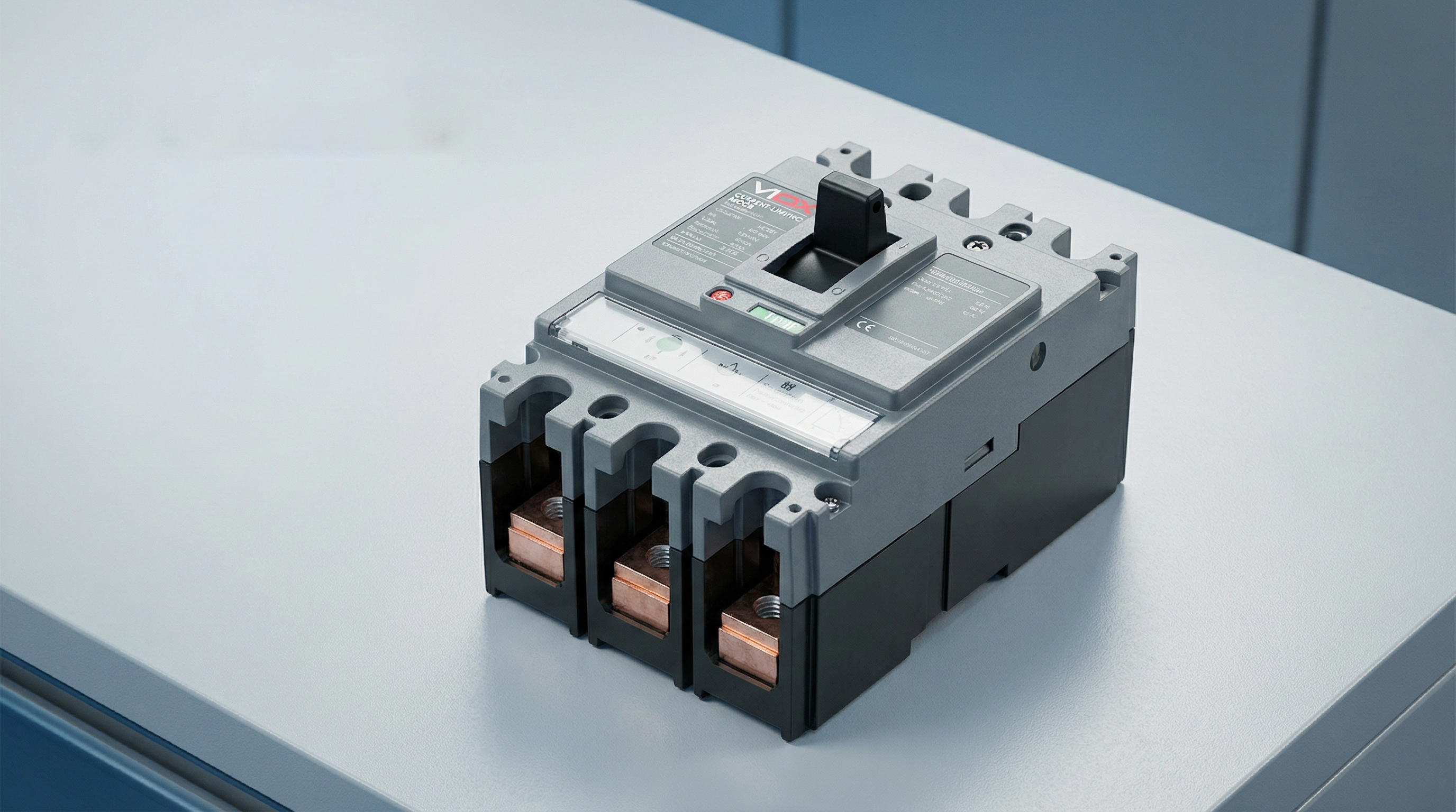
限流断路器代表了电路保护技术的一项根本性进步。与在交流波形自然过零点处切断故障的传统断路器不同,限流断路器能在毫秒级时间内动作,在故障电流达到其破坏性峰值之前将其扼制。这种快速干预极大地降低了电气设备所承受的机械应力和热应力,保护敏感电子设备免受损坏,并显著减轻电弧闪光的危害。.
对于设计配电系统的电气工程师、选择保护设备的盘柜制造商以及负责关键基础设施的设施管理人员而言,理解限流技术至关重要。本指南将阐述限流断路器的工作原理、定义其性能的关键技术规格,以及该技术在哪些情况下相比标准电路保护能提供关键优势。.
什么是限流断路器?
{"70":"একটি কারেন্ট লিমিটিং সার্কিট ব্রেকার হল একটি সুরক্ষামূলক ডিভাইস যা শর্ট-সার্কিট কারেন্ট তার সম্ভাব্য সর্বোচ্চ শিখর মান পৌঁছানোর আগেই বাধা দেওয়ার জন্য তৈরি করা হয়েছে। এই ক্ষমতা এটিকে প্রচলিত সার্কিট ব্রেকার থেকে আলাদা করে, যা সাধারণত একটি স্বাভাবিক শূন্য ক্রসিং এ বাধা দেওয়ার আগে ফল্ট কারেন্টকে তার পুরো শিখরে পৌঁছানোর অনুমতি দেয়।"}.
{"71":"যখন কোনও বৈদ্যুতিক সিস্টেমে শর্ট সার্কিট হয়, তখন কারেন্ট অত্যন্ত উচ্চ হারে বাড়তে শুরু করে—সম্ভাব্যভাবে কয়েক মিলিসেকেন্ডের মধ্যে কয়েক হাজার অ্যাম্পিয়ারে পৌঁছতে পারে। একটি স্ট্যান্ডার্ড সার্কিট ব্রেকার এই ত্রুটিপূর্ণ অবস্থা সনাক্ত করে এবং এর ট্রিপ প্রক্রিয়া শুরু করে, তবে বাধা দেওয়ার প্রক্রিয়াটিতে সময় লাগে। এই সংক্ষিপ্ত ব্যবধানের মধ্যে, ফল্ট কারেন্ট তার পুরো সম্ভাব্য শিখরে পৌঁছতে পারে, প্রচুর শক্তি নির্গত করে যা কন্ডাক্টর, বাসবার এবং ডাউনস্ট্রিম সরঞ্জামগুলিতে চাপ সৃষ্টি করে।"}.
{“72”:"অন্যদিকে, কারেন্ট লিমিটিং সার্কিট ব্রেকারগুলি অসাধারণ গতিতে কাজ করে। UL 489 ( molded case circuit breakers এর জন্য উত্তর আমেরিকার স্ট্যান্ডার্ড) অনুসারে, একটি সার্কিট ব্রেকারকে "কারেন্ট লিমিটিং" হিসাবে বিবেচনা করা হয় যদি এটি অর্ধ চক্রের চেয়ে কম সময়ে ত্রুটি দূর করে—সাধারণত 10 মিলিসেকেন্ডের নিচে। এই দ্রুত প্রতিক্রিয়া একটি উচ্চ আর্ক ভোল্টেজ তৈরি করে যা সিস্টেম ভোল্টেজের বিরোধিতা করে, কার্যকরভাবে কারেন্টের প্রবাহ বন্ধ করে দেয় এবং সম্ভাব্য ফল্ট কারেন্টের চেয়ে শিখর কারেন্টকে অনেক কম মানে নামিয়ে আনে।"}.
{"73":"ফলাফল নাটকীয়: যেখানে একটি সম্ভাব্য ফল্ট কারেন্ট 50,000 অ্যাম্পিয়ার আরএমএস সিমেট্রিক্যাল হতে পারে, সেখানে একটি কারেন্ট-লিমিটিং ব্রেকার প্রকৃত শিখর কারেন্টকে 15,000 অ্যাম্পিয়ার বা তার চেয়েও কমিয়ে দিতে পারে। শিখর কারেন্ট এবং মোট ফল্ট শক্তির এই হ্রাস ডাউনস্ট্রিম সরঞ্জামকে যান্ত্রিক শক্তি, তাপীয় ক্ষতি এবং আর্ক ফ্ল্যাশ বিপদ থেকে রক্ষা করে যা অন্যথায় ঘটতে পারত।"}.
{"74":"কারেন্ট লিমিটিং সার্কিট ব্রেকার কীভাবে কাজ করে"}
{"78":"এই সার্কিট ব্রেকারগুলির কারেন্ট-লিমিটিং ক্ষমতা যান্ত্রিক নকশা, ইলেক্ট্রোম্যাগনেটিক ফিজিক্স এবং আর্ক ব্যবস্থাপনার একটি সাবধানে ইঞ্জিনিয়ার করা সংমিশ্রণের ফল। প্রক্রিয়াটি বেশ কয়েকটি সমন্বিত প্রক্রিয়ার মাধ্যমে মিলিসেকেন্ডের মধ্যে উন্মোচিত হয়।"}.
{"79":"ইলেক্ট্রোডাইনামিক কন্টাক্ট সেপারেশন"}
{"80":"প্রথম গুরুত্বপূর্ণ উপাদানটি হল অতি-দ্রুত কন্টাক্ট সেপারেশন। যখন একটি উচ্চ ফল্ট কারেন্ট ব্রেকারের কন্টাক্টের মধ্য দিয়ে প্রবাহিত হয়, তখন এই কারেন্ট দ্বারা উত্পন্ন বিশাল চৌম্বক ক্ষেত্রগুলি শক্তিশালী ইলেক্ট্রোডাইনামিক শক্তি তৈরি করে। কারেন্ট-লিমিটিং ব্রেকারগুলি কন্টাক্ট কনফিগারেশনগুলির সাথে ডিজাইন করা হয়েছে যা পৃথকীকরণে সহায়তা করার জন্য এই শক্তিগুলিকে কাজে লাগায়—কন্টাক্টগুলি এমনভাবে সাজানো হয় যাতে চৌম্বক ক্ষেত্র একটি বিকর্ষণকারী শক্তি তৈরি করে যা আক্ষরিক অর্থে কন্টাক্টগুলিকে আলাদা করে দেয়।"}.
{“81”:"এই "ইলেক্ট্রোডাইনামিক রিপালশন" মানে হল যে উচ্চ ফল্ট কারেন্ট আসলে কন্টাক্ট সেপারেশনকে ত্বরান্বিত করে। ব্রেকারটি কেবল ট্রিপ মেকানিজমের যান্ত্রিক শক্তির উপর নির্ভর করে না; ফল্ট কারেন্ট নিজেই কন্টাক্টগুলি দ্রুত খোলার জন্য শক্তি সরবরাহ করে। এটি অত্যন্ত দ্রুত কন্টাক্ট সেপারেশন নিশ্চিত করে—প্রায়শই ফল্ট শুরু হওয়ার 1-2 মিলিসেকেন্ডের মধ্যে।"}.
{"82":"আর্ক গঠন এবং প্রসারণ"}
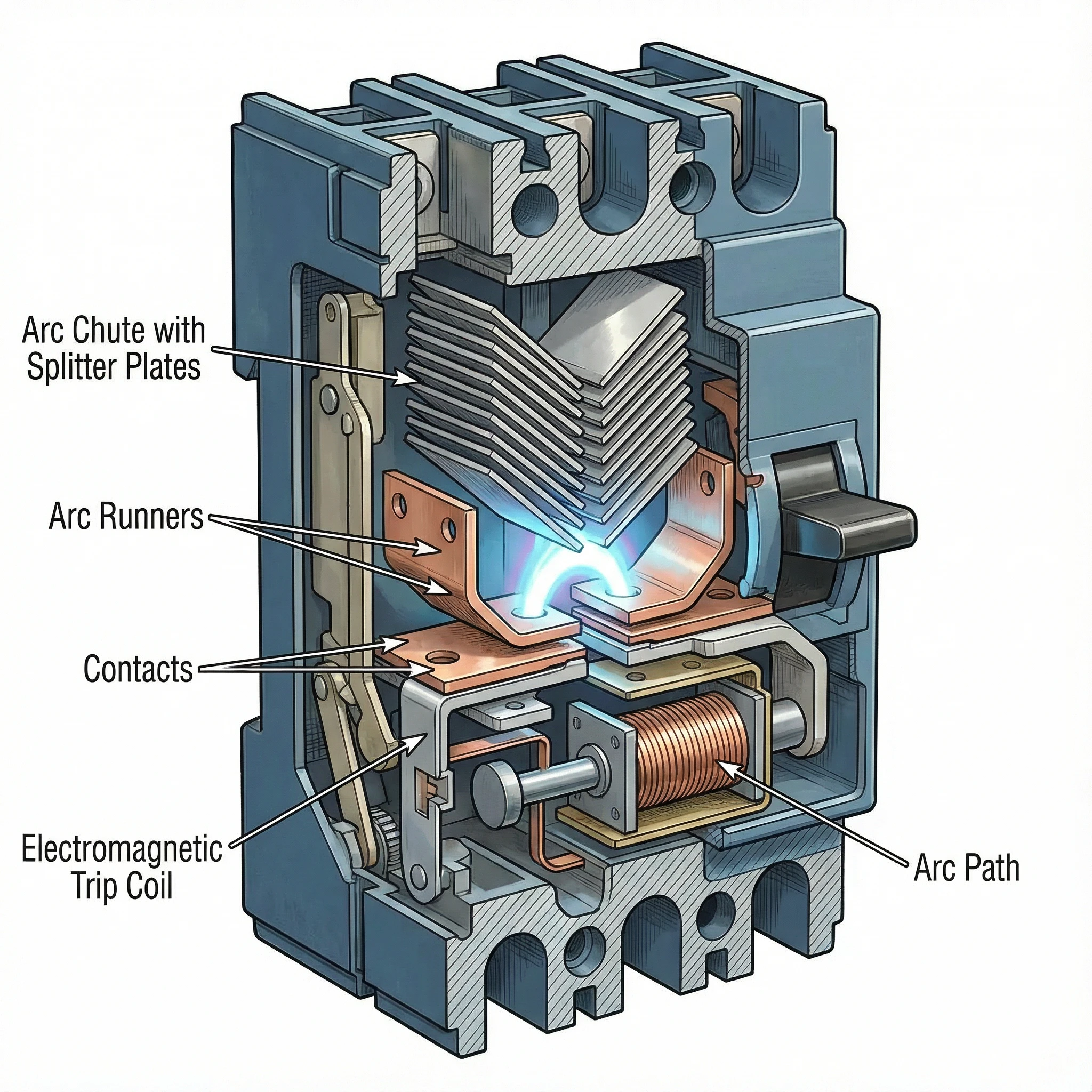
{"83":"উচ্চ গতিতে কন্টাক্টগুলি আলাদা হওয়ার সাথে সাথে ফাঁকে একটি বৈদ্যুতিক আর্ক তৈরি হয়। দমন করার জন্য সমস্যা হওয়ার পরিবর্তে, এই আর্ক কারেন্ট সীমাবদ্ধ করার প্রাথমিক হাতিয়ার হয়ে ওঠে। ব্রেকারের অভ্যন্তরীণ জ্যামিতি এই আর্কটিকে দ্রুত কন্টাক্টগুলি থেকে দূরে এবং বিশেষভাবে ডিজাইন করা আর্ক চেম্বারে (আর্ক চুট নামে পরিচিত) সরানোর জন্য ডিজাইন করা হয়েছে।"}.
{"84":"কারেন্ট প্রবাহ দ্বারা উত্পন্ন চৌম্বক ক্ষেত্র এবং আর্ক রানারগুলির শারীরিক আকার আর্কটিকে উপরের দিকে আর্ক চুটে পরিচালিত করে। আর্কটি সরে গিয়ে প্রসারিত হওয়ার সাথে সাথে এর দৈর্ঘ্য নাটকীয়ভাবে বৃদ্ধি পায়। একটি দীর্ঘ আর্কের এটিকে টিকিয়ে রাখার জন্য উচ্চ ভোল্টেজের প্রয়োজন হয় এবং এই আর্ক ভোল্টেজ ফল্ট কারেন্ট চালিত সিস্টেম ভোল্টেজের বিরোধিতা করে।"}.
{"85":"আর্ক কমুটেশন এবং স্প্লিটিং"}
{“86”:"আর্ক চুটে ধাতব প্লেটের একটি সিরিজ রয়েছে যা একটি নির্দিষ্ট কনফিগারেশনে সাজানো (প্রায়শই V-আকৃতির), যাকে আর্ক স্প্লিটার বা আর্ক ডিভাইডার বলা হয়। আর্কটি যখন চুটের মধ্যে চালিত হয়, তখন এটি এই প্লেটগুলির সাথে যোগাযোগ করে এবং "কমুটেট" করে—মূল আর্ক পাথ থেকে স্প্লিটার প্লেটগুলিতে স্থানান্তরিত হয়।"}.
{"87":"এই প্রক্রিয়াটি কার্যকরভাবে একক উচ্চ-শক্তির আর্ককে একাধিক ছোট সিরিজে বিভক্ত করে। প্রতিটি ছোট আর্ক তার নিজস্ব ভোল্টেজ ড্রপ তৈরি করে। উদাহরণস্বরূপ, যদি আর্ক চুটে 20টি স্প্লিটার প্লেট থাকে, তবে মোট আর্ক ভোল্টেজ সিস্টেম ভোল্টেজের বহু গুণ বেশি হতে পারে। যখন ক্রমবর্ধমান আর্ক ভোল্টেজ সিস্টেম ভোল্টেজকে ছাড়িয়ে যায়, তখন কারেন্ট দ্রুত হ্রাস করতে বাধ্য হয়।"}.
{"88":"আর্ক কুলিং এবং নির্বাপণ"}
{"89":"ধাতব স্প্লিটার প্লেটগুলি হিট সিঙ্ক হিসাবেও কাজ করে, দ্রুত আর্কগুলিকে শীতল করে। প্লেটগুলি আর্কের পৃষ্ঠের ক্ষেত্রফল বাড়ায় এবং তাপ দূরে সরিয়ে নেয়। আশেপাশের বাতাস বা আর্ক-নির্বাপক গ্যাসের সাথে মিলিত হয়ে এই শীতলীকরণ আর্কের পরিবাহিতা হ্রাস করে।"}.
{"90":"উচ্চ আর্ক ভোল্টেজ (কারেন্ট প্রবাহের বিরোধিতা করে) এবং আর্ক কুলিং (পরিবাহিতা হ্রাস করে) এর মিথস্ক্রিয়া কারেন্টকে শূন্যের দিকে বাধ্য করে। ব্রেকার আর্কটিকে নিভিয়ে দেয় এবং ফল্ট দূর করে—সবকিছু একটি চক্রের ভগ্নাংশের মধ্যে, ফল্ট কারেন্ট তার সম্ভাব্য শিখরে পৌঁছানোর আগে।"}.
{"91":"এই পুরো ক্রম—ফল্ট সনাক্তকরণ থেকে শুরু করে কন্টাক্ট সেপারেশন, আর্ক প্রসারণ, স্প্লিটিং এবং নির্বাপণ—10 মিলিসেকেন্ডের মধ্যে ঘটে। কারেন্ট একটি স্বাভাবিক শূন্য ক্রসিং এ বাধাগ্রস্ত হয় না বরং জোর করে, এমন পরিস্থিতি তৈরি করে যেখানে আর্ক টিকিয়ে রাখা যায় না।"}.
মূল প্রযুক্তিগত স্পেসিফিকেশন
{"93":"কারেন্ট-লিমিটিং কর্মক্ষমতা বুঝতে হলে তিনটি গুরুত্বপূর্ণ স্পেসিফিকেশন সম্পর্কে পরিচিত হতে হবে যা একটি ব্রেকার কতটা কার্যকরভাবে ফল্ট কারেন্টকে সীমিত করে এবং ডাউনস্ট্রিম সরঞ্জামকে রক্ষা করে তা সংজ্ঞায়িত করে।"}.
{"95":"লেট-থ্রু কারেন্ট (Ip)"}
দ্য {"97":"লেট-থ্রু কারেন্ট (Ip)"} {"98":"হল ফল্টের সময় ব্রেকারের মধ্য দিয়ে প্রবাহিত প্রকৃত শিখর কারেন্ট, যা অ্যাম্পিয়ারে পরিমাপ করা হয়। এই মানটি ব্রেকারের কারেন্ট-লিমিটিং কার্যকারিতা উপস্থাপন করে: একটি নিম্ন Ip আরও ভাল কারেন্ট সীমাবদ্ধতা নির্দেশ করে।"}.
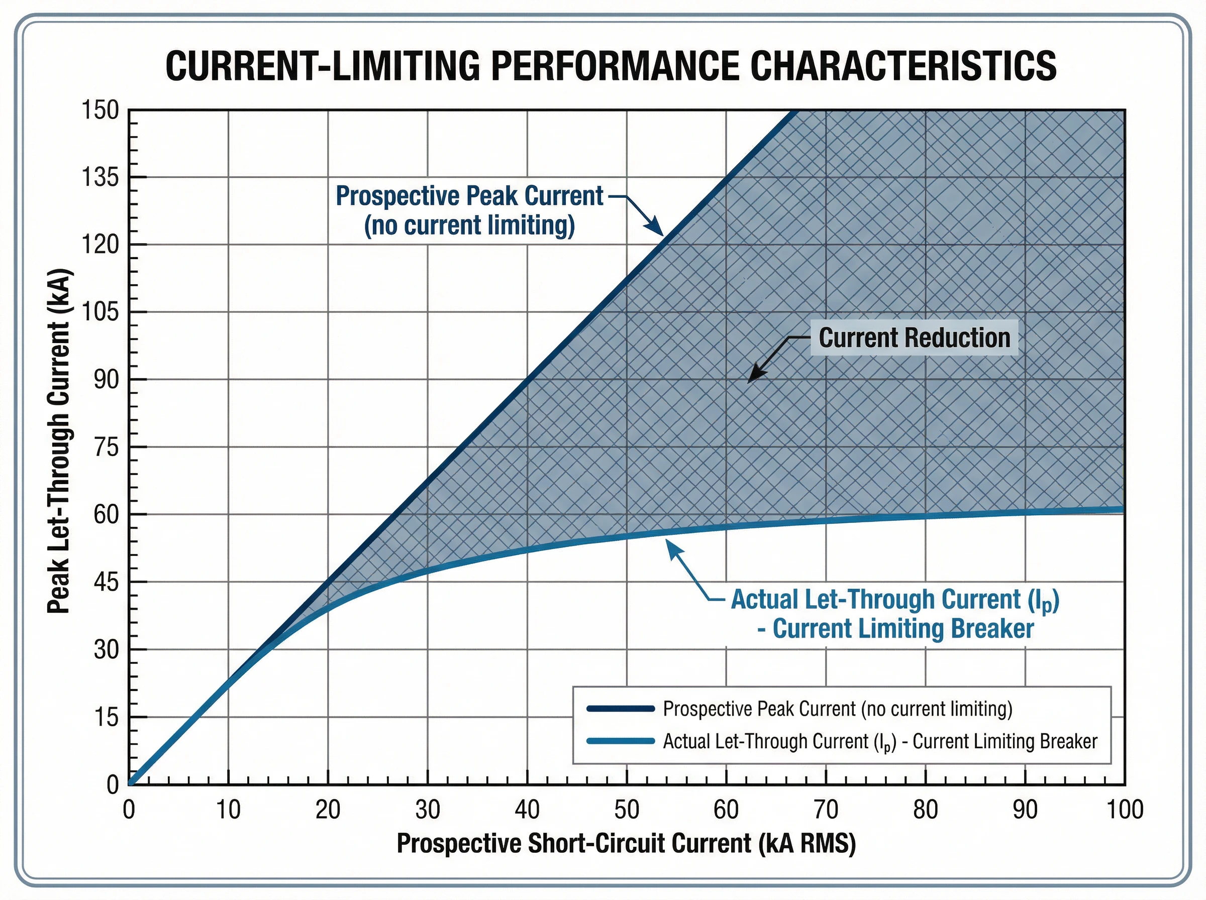
{"99":"নির্মাতারা বৈশিষ্ট্যযুক্ত কার্ভ আকারে লেট-থ্রু কারেন্ট ডেটা সরবরাহ করে। এই গ্রাফগুলি উল্লম্ব অক্ষের শিখর লেট-থ্রু কারেন্ট (Ip) কে অনুভূমিক অক্ষের সম্ভাব্য শর্ট-সার্কিট কারেন্টের (RMS সিমেট্রিক্যাল অ্যাম্পিয়ার) বিপরীতে প্লট করে। ইনস্টলেশন পয়েন্টে যে কোনও প্রদত্ত সম্ভাব্য ফল্ট স্তরের জন্য, কার্ভটি সর্বাধিক শিখর কারেন্ট দেখায় যা আসলে প্রবাহিত হবে।"}.
{"100":"উদাহরণস্বরূপ, যদি কোনও প্যানেলবোর্ডে উপলব্ধ ফল্ট কারেন্ট 42,000 অ্যাম্পিয়ার আরএমএস সিমেট্রিক্যাল হয়, তবে একটি কারেন্ট-লিমিটিং ব্রেকার প্রকৃত শিখর কারেন্টকে মাত্র 18,000 অ্যাম্পিয়ারে সীমাবদ্ধ করতে পারে। সম্ভাব্য থেকে প্রকৃত শিখর কারেন্টে এই হ্রাস বাসবারগুলিকে বাঁকানো থেকে রক্ষা করে, কন্ডাক্টরকে অতিরিক্ত গরম হওয়া থেকে বাধা দেয় এবং সমস্ত ডাউনস্ট্রিম উপাদানগুলির উপর যান্ত্রিক চাপ হ্রাস করে।"}.
{"101":"তাপীয় চাপ (I²t)"}
দ্য {"103":"I²t মান"} {“104”:"(উচ্চারণ করা হয় "আই-স্কয়ার্ড-টি"), যা অ্যাম্পিয়ার-স্কয়ার্ড সেকেন্ডে (A²s) পরিমাপ করা হয়, ফল্ট ক্লিয়ারিংয়ের সময় ব্রেকার দ্বারা নির্গত তাপীয় শক্তিকে পরিমাণ দেয়। এটি মোট ক্লিয়ারিং সময়ের উপর কারেন্টের বর্গক্ষেত্রের অবিচ্ছেদ্য অংশকে উপস্থাপন করে।"}.
{"105":"এই স্পেসিফিকেশনটি কেবল এবং সংবেদনশীল ইলেকট্রনিক সরঞ্জাম রক্ষার জন্য গুরুত্বপূর্ণ। কেবলগুলির নিরোধকের একটি নির্দিষ্ট তাপীয় প্রতিরোধ ক্ষমতা রয়েছে যা I²t হিসাবে প্রকাশ করা হয়। যদি সুরক্ষামূলক ডিভাইসটি তারের সহ্য করার চেয়ে বেশি তাপীয় শক্তি নির্গত করে, তবে তারের শারীরিকভাবে গলে না গেলেও নিরোধক ক্ষতিগ্রস্থ হবে।"}.
{"106":"কারেন্ট-লিমিটিং ব্রেকারগুলি স্ট্যান্ডার্ড ব্রেকারের তুলনায় নাটকীয়ভাবে I²t হ্রাস করে। একই সম্ভাব্য ফল্ট কারেন্টের জন্য, একটি কারেন্ট-লিমিটিং ডিভাইসের একটি প্রচলিত ব্রেকারের চেয়ে 50-80% কম I²t মান থাকতে পারে। এই হ্রাসকৃত তাপীয় চাপ কন্ডাক্টরের ক্ষতি প্রতিরোধ করে, তারের নিরোধককে রক্ষা করে এবং সরঞ্জামের জীবনকাল বাড়ায়।"}.
{"107":"নির্মাতারা লেট-থ্রু কারেন্ট কার্ভের অনুরূপ I²t কার্ভ সরবরাহ করে, যা সম্ভাব্য ফল্ট কারেন্টের একটি ফাংশন হিসাবে সর্বাধিক তাপীয় শক্তি দেখায়। কিছু স্ট্যান্ডার্ড তাদের I²t কর্মক্ষমতার উপর ভিত্তি করে সার্কিট ব্রেকারের জন্য শক্তি-সীমাবদ্ধ শ্রেণী সংজ্ঞায়িত করে।"}.
{"108":"ব্রেকিং ক্যাপাসিটি (Icu এবং Ics)"}
দ্য {"110":"ব্রেকিং ক্যাপাসিটি"} {"111":"সর্বাধিক ফল্ট কারেন্টকে সংজ্ঞায়িত করে যা ব্রেকার নিরাপদে বাধা দিতে পারে। IEC 60947-2 (নিম্ন-ভোল্টেজ সার্কিট ব্রেকারের জন্য আন্তর্জাতিক মান) এর অধীনে দুটি রেটিং প্রাসঙ্গিক:"}
- চূড়ান্ত ব্রেকিং ক্ষমতা (আইসিইউ){"113":": সর্বাধিক ফল্ট কারেন্ট যা ব্রেকার ধ্বংস না হয়ে বাধা দিতে পারে। Icu স্তরে একটি ফল্ট বাধা দেওয়ার পরে, ব্রেকারটি ক্রমাগত পরিষেবার জন্য উপযুক্ত নাও হতে পারে এবং প্রতিস্থাপনের প্রয়োজন হতে পারে। এটি ব্রেকারের পরম উপরের সীমা উপস্থাপন করে।"}.
- সার্ভিস ব্রেকিং ক্যাপাসিটি (আইসিএস){"115":": সর্বাধিক ফল্ট কারেন্ট যা ব্রেকার একাধিকবার বাধা দিতে পারে এবং ক্রমাগত পরিষেবার জন্য সম্পূর্ণরূপে কার্যকরী এবং নির্ভরযোগ্য থাকতে পারে। Ics কে Icu এর শতাংশ হিসাবে প্রকাশ করা হয় (সাধারণত 50%, 75% বা 100%)। উচ্চ নির্ভরযোগ্যতার প্রয়োজন এমন গুরুত্বপূর্ণ অ্যাপ্লিকেশনগুলির জন্য, Ics = 100% Icu সহ ব্রেকারগুলি পছন্দ করা হয়।"}.
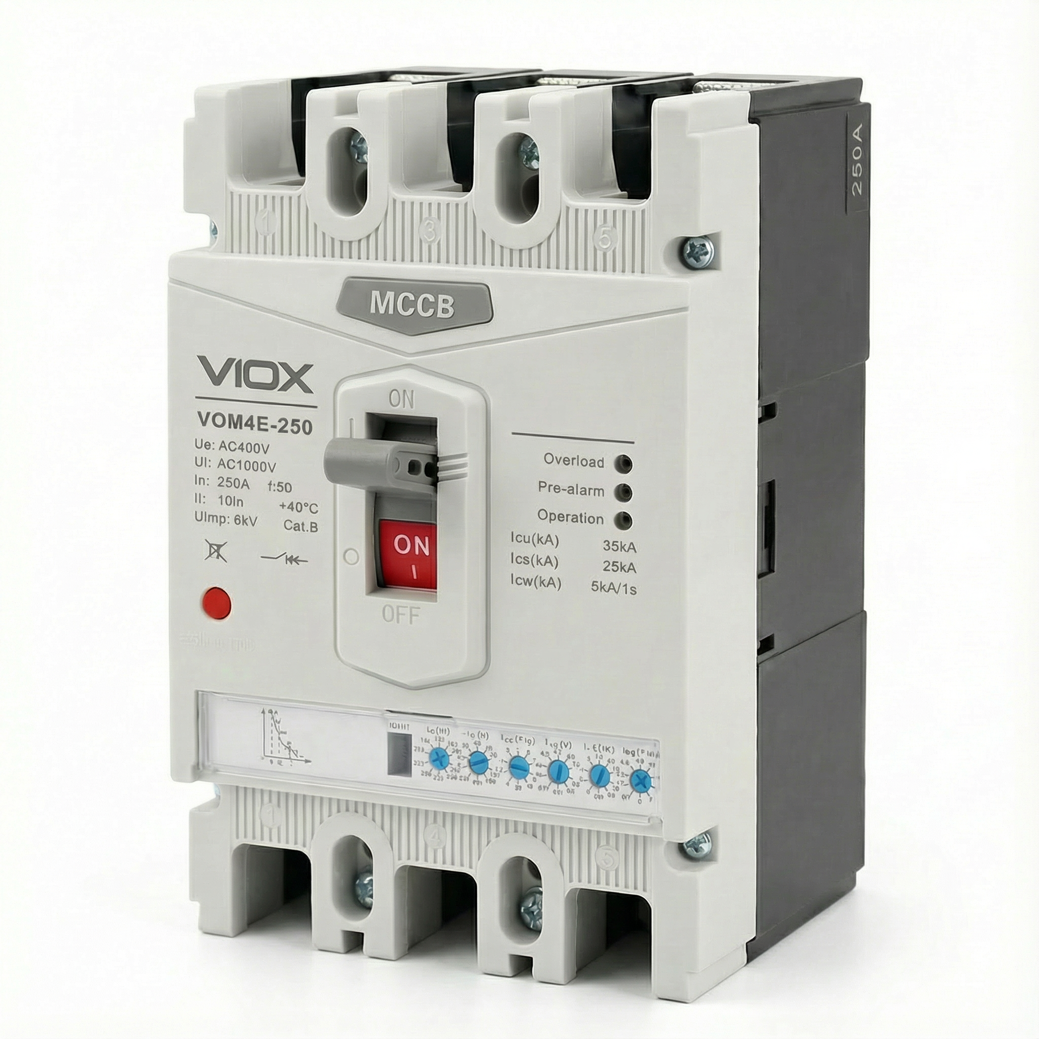
{"116":"মৌলিক নির্বাচন নিয়মটি সরল: ব্রেকারের Icu অবশ্যই ইনস্টলেশন পয়েন্টে সম্ভাব্য শর্ট-সার্কিট কারেন্টের সমান বা তার চেয়ে বেশি হতে হবে। কারেন্ট-লিমিটিং ব্রেকারগুলি কমপ্যাক্ট ফর্ম ফ্যাক্টরে উচ্চ ব্রেকিং ক্যাপাসিটি (50kA, 85kA, বা তার বেশি) অর্জন করতে পারে কারণ কারেন্ট-লিমিটিং ক্রিয়াটি নিজেই ব্রেকারকে যে শক্তি পরিচালনা করতে হবে তা হ্রাস করে।"}.
{"117":"স্পেসিফিকেশনগুলির আন্তঃসম্পর্ক"}
{"118":"এই স্পেসিফিকেশনগুলি সুরক্ষা কর্মক্ষমতা সংজ্ঞায়িত করতে একসাথে কাজ করে। যখন ব্রেকারের Icu রেটিং পর্যন্ত একটি ফল্ট ঘটে, তখন কারেন্ট-লিমিটিং ক্রিয়া শিখর কারেন্ট (Ip) এবং মোট তাপীয় শক্তি (I²t) উভয়কেই সম্ভাব্য ফল্ট যা তৈরি করত তার চেয়ে অনেক কম মানে কমিয়ে দেয়। শিখর যান্ত্রিক চাপ এবং তাপীয় ক্ষতির এই সমন্বিত হ্রাসই কারেন্ট-লিমিটিং ব্রেকারগুলিকে উচ্চ উপলব্ধ ফল্ট কারেন্ট সহ আধুনিক বৈদ্যুতিক সিস্টেম রক্ষার জন্য অপরিহার্য করে তোলে।"}.
{"119":"মান এবং সম্মতি"}
{"120":"কারেন্ট-লিমিটিং সার্কিট ব্রেকারগুলি কঠোর আন্তর্জাতিক এবং আঞ্চলিক মান দ্বারা পরিচালিত হয় যা কর্মক্ষমতা প্রয়োজনীয়তা, পরীক্ষার পদ্ধতি এবং সুরক্ষা মানদণ্ড সংজ্ঞায়িত করে।"}.
{"122":"IEC 60947-2: আন্তর্জাতিক মান"}
আইইসি 60947-2 {"124":"শিল্প এবং বাণিজ্যিক অ্যাপ্লিকেশনগুলিতে ব্যবহৃত নিম্ন-ভোল্টেজ সার্কিট ব্রেকারের জন্য আন্তর্জাতিক মান। এই বিস্তৃত মানটি প্রতিষ্ঠা করে:"}
- {"125":"কর্মক্ষমতা বিভাগ"}{"126":": স্ট্যান্ডার্ডটি ক্যাটাগরি এ ব্রেকারগুলির (কোনও ইচ্ছাকৃত শর্ট-সার্কিট সময় বিলম্ব নেই) এবং ক্যাটাগরি বি ব্রেকারগুলির (স্বল্প-সময় সহ্য করার ক্ষমতা সহ) মধ্যে পার্থক্য করে। বেশিরভাগ আধুনিক কারেন্ট-লিমিটিং MCCB হল ক্যাটাগরি এ ডিভাইস।"}.
- 127: ব্রেকিং ক্ষমতা যাচাইকরণ128: IEC 60947-2 চূড়ান্ত ব্রেকিং ক্ষমতা (Icu) এবং পরিষেবা ব্রেকিং ক্ষমতা (Ics) উভয়ই যাচাই করার জন্য কঠোর পরীক্ষা ক্রম নির্দিষ্ট করে। এই পরীক্ষাগুলিতে নির্দিষ্ট ফল্ট পরিস্থিতিতে একাধিক মেকিং এবং ব্রেকিং অপারেশন জড়িত।.
- 129: কারেন্ট-লিমিটিং কর্মক্ষমতা130: স্ট্যান্ডার্ড কারেন্ট লিমিটেশন বাধ্যতামূলক না করলেও, কারেন্ট-লিমিটিং ক্ষমতা দাবি করা ব্রেকারের জন্য লেট-থ্রু কারেন্ট এবং I²t কর্মক্ষমতা যাচাই এবং নথিভুক্ত করার জন্য পরীক্ষার পদ্ধতি প্রদান করে।.
- 131: সমন্বয় এবং নির্বাচনীতা132: স্ট্যান্ডার্ড ব্যাক-আপ সুরক্ষা (ক্যাসকেডিং)-এর জন্য প্রয়োজনীয়তা প্রতিষ্ঠা করে, যেখানে একটি কারেন্ট-লিমিটিং ব্রেকার আপস্ট্রিম তার অবস্থানের সম্ভাব্য ফল্ট কারেন্টের চেয়ে কম ব্রেকিং ক্ষমতা সহ একটি ডাউনস্ট্রিম ব্রেকারকে রক্ষা করে।.
133: UL 489: উত্তর আমেরিকার স্ট্যান্ডার্ড
ইউএল ৪৮৯ 135: হল উত্তর আমেরিকাতে মোল্ডেড কেস সার্কিট ব্রেকারের জন্য আন্ডাররাইটার্স ল্যাবরেটরিজ স্ট্যান্ডার্ড। মূল বিধানগুলির মধ্যে রয়েছে:
- 136: কারেন্ট-লিমিটিং সংজ্ঞা137: UL 489 নির্দিষ্ট করে যে একটি সার্কিট ব্রেকার “কারেন্ট লিমিটিং” হিসাবে যোগ্যতা অর্জন করে যদি এটি অর্ধ চক্রের কম সময়ে একটি ফল্ট পরিষ্কার করে (সাধারণত 60 Hz সিস্টেমের জন্য 10 মিলিসেকেন্ডের নিচে)।.
- 138: লেট-থ্রু টেস্টিং139: স্ট্যান্ডার্ডের জন্য লেট-থ্রু কারেন্ট কার্ভ তৈরি করার জন্য ব্যাপক পরীক্ষার প্রয়োজন যা সম্ভাব্য ফল্ট কারেন্টের একটি ফাংশন হিসাবে প্রকৃত পিক কারেন্ট দেখায়।.
- 140: শর্ট-সার্কিট রেটিং141: UL 489 ইন্টারাপ্টিং রেটিং (IR) সংজ্ঞায়িত করে এবং রেটেড ভোল্টেজ এবং কারেন্ট স্তরে ব্রেকার কর্মক্ষমতা যাচাই করার জন্য পরীক্ষার পদ্ধতি প্রতিষ্ঠা করে।.
সম্মতি এবং সার্টিফিকেশন
143: বৈদ্যুতিক সিস্টেম ডিজাইনার এবং স্পেসিফায়ারদের জন্য, স্ট্যান্ডার্ড সম্মতি নিশ্চিত করে:
- 144: যাচাইকৃত কর্মক্ষমতা145: সার্টিফাইড ব্রেকারগুলি তাদের কারেন্ট-লিমিটিং ক্ষমতা এবং ব্রেকিং ক্ষমতা নিশ্চিত করার জন্য কঠোর তৃতীয় পক্ষের পরীক্ষার মধ্য দিয়ে গেছে।.
- 146: ডিজাইনের আত্মবিশ্বাস147: প্রকৌশলীরা সরঞ্জাম সুরক্ষা বিশ্লেষণ এবং আর্ক ফ্ল্যাশ গণনার জন্য প্রকাশিত লেট-থ্রু কার্ভ এবং I²t ডেটার উপর নির্ভর করতে পারেন।.
- 148: নিয়ন্ত্রক স্বীকৃতি149: স্ট্যান্ডার্ড-কমপ্লায়েন্ট ব্রেকারগুলি তাদের নিজ নিজ বাজারের বৈদ্যুতিক কোড প্রয়োজনীয়তা পূরণ করে (IEC জোন বা উত্তর আমেরিকার ইনস্টলেশন)।.
150: VIOX কারেন্ট-লিমিটিং সার্কিট ব্রেকারগুলি IEC 60947-2 এবং UL 489 উভয় প্রয়োজনীয়তা পূরণের জন্য ডিজাইন এবং পরীক্ষা করা হয়েছে, যা বিশ্বব্যাপী প্রযোজ্যতা এবং যাচাইকৃত সুরক্ষা কর্মক্ষমতা নিশ্চিত করে।.
প্রয়োগ এবং ব্যবহারের ক্ষেত্রে
152: কারেন্ট-লিমিটিং সার্কিট ব্রেকারগুলি বৈদ্যুতিক সিস্টেমে গুরুত্বপূর্ণ সুবিধা প্রদান করে যেখানে উচ্চ উপলব্ধ ফল্ট কারেন্ট সরঞ্জাম অখণ্ডতা এবং কর্মীদের নিরাপত্তার জন্য হুমকি।.
153: ডেটা সেন্টার এবং ক্রিটিক্যাল আইটি ইনফ্রাস্ট্রাকচার
154: আধুনিক ডেটা সেন্টারগুলি অসাধারণ ফল্ট কারেন্ট চ্যালেঞ্জের মুখোমুখি। উচ্চ-ঘনত্বের সার্ভার র্যাক, শক্তিশালী ইউপিএস সিস্টেম এবং একাধিক ইউটিলিটি ফিড উপলব্ধ ফল্ট কারেন্ট তৈরি করে যা 65kA বা তার বেশি হতে পারে। এই পরিবেশগুলিতে কারেন্ট-লিমিটিং ব্রেকারগুলি অপরিহার্য:
- 155: আইটি সরঞ্জাম সুরক্ষা156: সার্ভার, স্টোরেজ অ্যারে এবং নেটওয়ার্কিং গিয়ারে সংবেদনশীল ইলেকট্রনিক্স থাকে যা এমনকি সংক্ষিপ্ত ওভারকারেন্ট ইভেন্টের জন্য ঝুঁকিপূর্ণ। কারেন্ট-লিমিটিং ব্রেকারগুলি ফল্ট শক্তিকে এমন স্তরে কমিয়ে দেয় যা উপাদানের ক্ষতি প্রতিরোধ করে।.
- নির্বাচনী সমন্বয়158: ডেটা সেন্টারের নির্ভরযোগ্যতা ক্যাসকেডিং বিভ্রাট ছাড়াই ফল্টগুলি বিচ্ছিন্ন করার উপর নির্ভর করে। কারেন্ট-লিমিটিং ব্রেকারগুলি আপস্ট্রিম এবং ডাউনস্ট্রিম সুরক্ষার মধ্যে সমন্বয় সহজতর করে, শুধুমাত্র প্রভাবিত সার্কিট ট্রিপ নিশ্চিত করে।.
- 159: আর্ক ফ্ল্যাশ প্রশমন160: রক্ষণাবেক্ষণ কর্মীরা নিয়মিতভাবে এনার্জাইজড সরঞ্জামগুলিতে কাজ করে। পিক ফল্ট কারেন্ট এবং ক্লিয়ারিং সময় কমিয়ে, কারেন্ট-লিমিটিং ব্রেকারগুলি নাটকীয়ভাবে আর্ক ফ্ল্যাশ ইনসিডেন্ট শক্তি হ্রাস করে, কর্মীদের নিরাপত্তা উন্নত করে এবং সম্ভাব্যভাবে পিপিই প্রয়োজনীয়তা হ্রাস করে।.
- 161: কমপ্যাক্ট ইনস্টলেশন162: কারেন্ট-লিমিটিং প্রযুক্তি কমপ্যাক্ট MCCB-তে উচ্চ ব্রেকিং ক্ষমতা (50kA-100kA) সক্ষম করে, অতিরিক্ত আকারের সুইচগিয়ারের প্রয়োজন ছাড়াই ঘন পাওয়ার বিতরণ সমর্থন করে।.
163: শিল্প উত্পাদন সুবিধা
164: বড় মোটর, ট্রান্সফরমার এবং বিস্তৃত বিতরণ নেটওয়ার্ক সহ শিল্প কারখানাগুলি ফল্ট কারেন্টের মুখোমুখি হয় যা উত্পাদন সরঞ্জামের ক্ষতি করতে পারে:
- মোটর নিয়ন্ত্রণ কেন্দ্র166: মোটর স্টার্টার, ভেরিয়েবল ফ্রিকোয়েন্সি ড্রাইভ এবং ফল্ট কারেন্ট স্ট্রেস থেকে নিয়ন্ত্রণ ইলেকট্রনিক্স রক্ষা করা। কারেন্ট-লিমিটিং ব্রেকারগুলি ব্যয়বহুল ড্রাইভ ইলেকট্রনিক্সের ক্ষতি প্রতিরোধ করে এবং উত্পাদন ধারাবাহিকতা নিশ্চিত করে।.
- 167: উচ্চ-ক্ষমতার ফিডার168: যেখানে একাধিক পাওয়ার উত্স বা বড় ট্রান্সফরমার 50kA-এর বেশি ফল্ট কারেন্ট তৈরি করে, সেখানে কারেন্ট-লিমিটিং ব্রেকারগুলি পুরো সিস্টেমে ব্যয়বহুল উচ্চ-ইন্টারাপ্টিং-ক্ষমতার সুইচগিয়ারের প্রয়োজন ছাড়াই সুরক্ষা প্রদান করে।.
- সরঞ্জাম সুরক্ষা170: বাসবার, কেবল ট্রে এবং প্যানেল উপাদানগুলির যান্ত্রিক শক্তির সীমা রয়েছে। কারেন্ট-লিমিটিং ব্রেকারগুলি ফল্টের সময় চৌম্বকীয় শক্তি হ্রাস করে, বিতরণ অবকাঠামোর শারীরিক ক্ষতি প্রতিরোধ করে।.
171: উচ্চ পাওয়ার ঘনত্ব সহ বাণিজ্যিক ভবন
172: অফিস টাওয়ার, হাসপাতাল এবং খুচরা কেন্দ্রগুলি ক্রমবর্ধমানভাবে উচ্চ-পাওয়ার সিস্টেম স্থাপন করে:
- 173: প্রধান এবং উপ-প্রধান বিতরণ174: প্রধান পরিষেবা প্রবেশপথ এবং বিতরণ বোর্ডগুলিতে কারেন্ট-লিমিটিং ব্রেকারগুলি ইউটিলিটি-সরবরাহকৃত ফল্ট কারেন্ট থেকে রক্ষা করে এবং কার্যকর ডাউনস্ট্রিম সমন্বয় সক্ষম করে।.
- 175: জরুরি পাওয়ার সিস্টেম176: জেনারেটর এবং ট্রান্সফার সুইচ সুরক্ষা যেখানে একাধিক উত্স উপলব্ধ ফল্ট কারেন্ট বৃদ্ধি করে।.
- 177: সংস্কার এবং সম্প্রসারণ178: বিদ্যমান বিল্ডিংগুলিতে ক্ষমতা যোগ করলে প্রায়শই ফল্ট কারেন্টের মাত্রা বৃদ্ধি পায়। কারেন্ট-লিমিটিং ব্রেকারগুলি কখনও কখনও বিদ্যমান অবকাঠামো রেটিংয়ের মধ্যে পর্যাপ্ত সুরক্ষা প্রদান করে সম্পূর্ণ সিস্টেম আপগ্রেডের প্রয়োজনীয়তা দূর করতে পারে।.
179: ক্যাসকেডিং সুরক্ষা (ব্যাক-আপ সুরক্ষা)
180: সবচেয়ে মূল্যবান অ্যাপ্লিকেশনগুলির মধ্যে একটি হল ক্যাসকেডিং বা সিরিজ রেটিং সক্ষম করা। আপস্ট্রিমে ইনস্টল করা একটি কারেন্ট-লিমিটিং ব্রেকার ডাউনস্ট্রিম ব্রেকারগুলিকে তাদের অবস্থানের সম্ভাব্য ফল্ট কারেন্টের চেয়ে কম ব্রেকিং ক্ষমতা দিয়ে রক্ষা করতে পারে। এটি নিম্নলিখিতগুলির অনুমতি দেয়:
- 181: খরচ অপ্টিমাইজেশন182: সম্পূর্ণ সুরক্ষা বজায় রেখে ডাউনস্ট্রিমে কম ব্যয়বহুল, নিম্ন-রেটেড ব্রেকার ব্যবহার করা।.
- ১৮৩: সরলীকৃত স্পেসিফিকেশন১৮৪: : পুরো সুবিধা জুড়ে সাধারণ ব্রেকার প্রকারের উপর স্ট্যান্ডার্ডাইজ করা যখন বর্তমান-সীমাবদ্ধ প্রধান ব্রেকার সিস্টেম-ব্যাপী সুরক্ষা প্রদান করে।.
- ১৮৫: সিস্টেমের নমনীয়তা১৮৬: : সমস্ত ডাউনস্ট্রিম সুরক্ষা ডিভাইস আপগ্রেড না করেই সার্কিট বা লোড যোগ করা।.
১৮৭: কারেন্ট লিমিটার বনাম স্ট্যান্ডার্ড সার্কিট ব্রেকার
১৮৮: কারেন্ট-লিমিটিং এবং স্ট্যান্ডার্ড সার্কিট ব্রেকারের মধ্যে পার্থক্য বোঝালে কখন কোন প্রযুক্তি উপযুক্ত তা স্পষ্ট করা যায়।.
১৯০: বাধা দেওয়ার পদ্ধতি
১৯১: স্ট্যান্ডার্ড ব্রেকার১৯২: : প্রচলিত সার্কিট ব্রেকার একটি ত্রুটি সনাক্ত করে এবং ট্রিপ প্রক্রিয়া শুরু করে, তবে ফল্ট কারেন্টকে তার সম্ভাব্য শিখর মান পর্যন্ত বাড়তে দেয়। বাধা সাধারণত ০.৫ থেকে ১.৫ চক্র (৬০ হার্জে ৮-২৫ মিলিসেকেন্ড) পরে একটি স্বাভাবিক কারেন্ট শূন্য ক্রসিংয়ে বা তার কাছাকাছি ঘটে। এই সময়ে, পুরো ফল্ট কারেন্ট সিস্টেমের উপর চাপ সৃষ্টি করে।.
১৯৩: কারেন্ট-লিমিটিং ব্রেকার১৯৪: : এই ডিভাইসগুলি সম্ভাব্য শিখরে পৌঁছানোর আগে কারেন্টকে জোর করে বাধা দিতে কয়েক মিলিসেকেন্ডের মধ্যে কাজ করে। ইলেক্ট্রোডাইনামিক কন্টাক্ট বিচ্ছেদ এবং আর্ক ভোল্টেজ বিল্ড-আপের মাধ্যমে, তারা অর্ধ চক্রের কম সময়ে (১০ মিলিসেকেন্ডের নিচে) ত্রুটি দূর করে, যা পিক কারেন্ট এবং মোট ফল্ট শক্তি উভয়ই নাটকীয়ভাবে হ্রাস করে।.
১৯৫: পিক কারেন্ট এবং যান্ত্রিক চাপ
১৯১: স্ট্যান্ডার্ড ব্রেকার১৯৭: : সম্পূর্ণ সম্ভাব্য ফল্ট কারেন্ট প্রবাহিত হয়, যা সর্বাধিক চৌম্বকীয় শক্তি তৈরি করে। একটি ৫০kA সম্ভাব্য ফল্টের জন্য, সম্পূর্ণ ৫০kA (৭০kA পিক অসিমেট্রিক্যাল) বাসবার, টার্মিনাল এবং সংযোগগুলিতে প্রচুর যান্ত্রিক চাপ তৈরি করে।.
১৯৩: কারেন্ট-লিমিটিং ব্রেকার১৯৯: : লেট-থ্রু কারেন্ট উল্লেখযোগ্যভাবে হ্রাস করা হয়। একই ৫০kA সম্ভাব্য ফল্টের জন্য, একটি কারেন্ট-লিমিটিং ব্রেকার প্রকৃত শিখরকে ১৫-২০kA-তে সীমাবদ্ধ করতে পারে, যা চৌম্বকীয় শক্তিকে ৬০-৭০% হ্রাস করে।.
২০০: তাপীয় শক্তি (I²t)
১৯১: স্ট্যান্ডার্ড ব্রেকার২০২: : দীর্ঘ ক্লিয়ারিং সময় এবং উচ্চতর পিক কারেন্টের ফলে যথেষ্ট তাপীয় শক্তি নির্গত হয়। কেবল, বাসবার এবং সংযোগগুলি উল্লেখযোগ্য তাপ শোষণ করে, যা সম্ভবত ইনসুলেশনকে ক্ষতিগ্রস্ত করে।.
১৯৩: কারেন্ট-লিমিটিং ব্রেকার২০৪: : হ্রাসকৃত পিক কারেন্ট এবং অতি-দ্রুত ক্লিয়ারিং নাটকীয়ভাবে I²t মান কমিয়ে দেয়, প্রায়শই ৫০-৮০% পর্যন্ত। এটি কেবল ইনসুলেশনকে রক্ষা করে, কন্ডাক্টর অ্যানিলিং প্রতিরোধ করে এবং সংবেদনশীল ইলেকট্রনিক্সকে তাপীয় চাপ থেকে রক্ষা করে।.
২০৫: আর্ক ফ্ল্যাশ ইনসিডেন্ট এনার্জি
১৯১: স্ট্যান্ডার্ড ব্রেকার২০৭: : উচ্চ ফল্ট কারেন্ট এবং দীর্ঘ ক্লিয়ারিং সময় আর্ক ফ্ল্যাশ ইনসিডেন্ট এনার্জি বৃদ্ধি করে, যার জন্য উচ্চ-স্তরের পিপিই প্রয়োজন হয় এবং রক্ষণাবেক্ষণ কর্মীদের জন্য বৃহত্তর সুরক্ষা ঝুঁকির সৃষ্টি করে।.
১৯৩: কারেন্ট-লিমিটিং ব্রেকার২০৯: : হ্রাসকৃত ফল্ট কারেন্টের মাত্রা এবং সময়কাল উল্লেখযোগ্যভাবে আর্ক ফ্ল্যাশ শক্তি হ্রাস করে। এটি আর্ক ফ্ল্যাশ সীমানা কমাতে পারে, পিপিই প্রয়োজনীয়তা হ্রাস করতে পারে এবং সামগ্রিক বৈদ্যুতিক সুরক্ষা উন্নত করতে পারে।.
২১০: খরচ এবং জটিলতার মধ্যে আপস
১৯১: স্ট্যান্ডার্ড ব্রেকার২১২: : সাধারণত প্রতি ইউনিটে কম ব্যয়বহুল। যে অ্যাপ্লিকেশনগুলিতে ফল্ট কারেন্ট মাঝারি এবং সরঞ্জামের রেটিং উপলব্ধ ফল্ট স্তরকে পর্যাপ্তভাবে ছাড়িয়ে যায় তার জন্য উপযুক্ত।.
১৯৩: কারেন্ট-লিমিটিং ব্রেকার২১৪: : প্রাথমিক খরচ বেশি, তবে নিম্নলিখিত উপায়ে মোট সিস্টেমের খরচ কমাতে পারে:
- ২১৫: হালকা-ডিউটির ডাউনস্ট্রিম উপাদানগুলির অনুমতি দেওয়া
- ২১৬: নিম্ন-রেটেড ব্রেকারগুলির সাথে ক্যাসকেডিং সুরক্ষা সক্ষম করা
- ২১৭: প্যানেল শক্তিবৃদ্ধি প্রয়োজনীয়তা হ্রাস করা
- ২১৮: ব্যয়বহুল সরঞ্জামকে ক্ষতি থেকে রক্ষা করা
- ২১৯: আর্ক ফ্ল্যাশ প্রশমন খরচ কমানো
প্রতিটি প্রকার কখন নির্বাচন করবেন
২২১: স্ট্যান্ডার্ড ব্রেকার কখন নির্বাচন করবেন:
- ২২২: উপলব্ধ ফল্ট কারেন্ট সিস্টেমের শর্ট-সার্কিট রেটিংয়ের থেকে অনেক কম হলে
- ২২৩: বাজেটের সীমাবদ্ধতা সবচেয়ে গুরুত্বপূর্ণ হলে এবং ফল্ট স্তর বর্তমান-সীমাবদ্ধ সুরক্ষাকে সমর্থন না করলে
- ২২৪: বর্তমান সীমাবদ্ধতা ছাড়াই সমন্বয় অর্জন করা গেলে
২২৫: কারেন্ট-লিমিটিং ব্রেকার কখন নির্বাচন করবেন:
- ২২৬: উপলব্ধ ফল্ট কারেন্ট ২০-২৫kA অতিক্রম করলে
- ২২৭: সংবেদনশীল ইলেকট্রনিক সরঞ্জাম রক্ষা করার জন্য (ডেটা সেন্টার, কন্ট্রোল সিস্টেম)
- ২২৮: আর্ক ফ্ল্যাশ বিপদ হ্রাস করার জন্য
- ২২৯: খরচ কমাতে ক্যাসকেডিং সুরক্ষা সক্ষম করার জন্য
- ২৩০: সুবিধা সম্প্রসারণের কারণে ফল্ট স্তর মূল সরঞ্জামের রেটিং ছাড়িয়ে গেলে
নির্বাচনের মানদণ্ড
২৩২: সঠিক কারেন্ট-লিমিটিং সার্কিট ব্রেকার নির্বাচন করতে বেশ কয়েকটি প্রযুক্তিগত এবং অ্যাপ্লিকেশন কারণ মূল্যায়ন করা প্রয়োজন।.
২৩৩: উপলব্ধ ফল্ট কারেন্ট গণনা করুন
২৩৪: প্রথম ধাপ হল ইনস্টলেশন পয়েন্টে সম্ভাব্য শর্ট-সার্কিট কারেন্ট নির্ধারণ করা। এর জন্য প্রয়োজন:
- ২৩৫: ইউটিলিটি ট্রান্সফরমারের ক্ষমতা এবং প্রতিবন্ধকতা
- ২৩৬: কন্ডাক্টরের দৈর্ঘ্য এবং আকার
- ২৩৭: বিতরণ উপাদানগুলির প্রতিবন্ধকতা
- ২৩৮: মোটর এবং জেনারেটরের অবদান
২৩৯: অনেক ইউটিলিটি ফল্ট কারেন্টের ডেটা সরবরাহ করে, অথবা যোগ্যতাসম্পন্ন বৈদ্যুতিক প্রকৌশলীরা শিল্প-মানক পদ্ধতি (IEC 60909 বা IEEE স্ট্যান্ডার্ড) ব্যবহার করে শর্ট-সার্কিট গণনা করতে পারেন। ব্রেকারের চূড়ান্ত ব্রেকিং ক্ষমতা (Icu) অবশ্যই এই গণনাকৃত ফল্ট কারেন্টের সমান বা তার বেশি হতে হবে।.
২৪০: সরঞ্জাম সুরক্ষা প্রয়োজনীয়তা মূল্যায়ন করুন
২৪১: বিবেচনা করুন কী সুরক্ষা প্রয়োজন:
- সংবেদনশীল ইলেকট্রনিক্স২৪৩: : ডেটা সেন্টার, কন্ট্রোল সিস্টেম এবং টেলিকমিউনিকেশন সরঞ্জাম হ্রাসকৃত লেট-থ্রু কারেন্ট এবং I²t থেকে উল্লেখযোগ্যভাবে উপকৃত হয়।.
- বাসবার এবং কন্ডাকটরের রেটিংফল্ট কারেন্ট যদি বাসবার, ক্যাবল বা প্যানেল কম্পোনেন্টের শর্ট-সার্কিট সহ্য করার রেটিং-এর কাছাকাছি হয় বা ছাড়িয়ে যায়, তাহলে কারেন্ট লিমিটেশন অপরিহার্য হয়ে পড়ে।.
- বিদ্যমান সরঞ্জামযখন সুযোগ-সুবিধা বাড়ানো হয়, তখন কারেন্ট-লিমিটিং ব্রেকারগুলো সম্পূর্ণ প্রতিস্থাপন ছাড়াই বিদ্যমান পরিকাঠামোকে রক্ষা করতে পারে।.
আর্ক ফ্ল্যাশ হ্যাজার্ড কমানোর প্রয়োজনীয়তা মূল্যায়ন করুন
আর্ক ফ্ল্যাশ স্টাডি যদি উচ্চ ঘটনা শক্তিস্তর নির্দেশ করে, যার জন্য ব্যাপক PPE প্রয়োজন অথবা যা কর্মীদের জন্য অগ্রহণযোগ্য বিপদ তৈরি করে, তাহলে কারেন্ট-লিমিটিং ব্রেকার উল্লেখযোগ্যভাবে আর্ক ফ্ল্যাশের শক্তি কমাতে পারে। কারেন্ট লিমিটেশন ঝুঁকির শ্রেণী কমাতে এবং নিরাপত্তা বাড়াতে পারবে কিনা, তা নির্ধারণ করতে আর্ক ফ্ল্যাশের হিসাবগুলো পর্যালোচনা করুন।.
সমন্বয় সংক্রান্ত প্রয়োজনীয়তা বিবেচনা করুন
সিলেক্টিভ কোঅর্ডিনেশন—অর্থাৎ ফল্টের সবচেয়ে কাছের ব্রেকারটিই শুধু ট্রিপ করবে—অনেক অ্যাপ্লিকেশনের জন্য গুরুত্বপূর্ণ:
- ক্যাসকেডিং সুরক্ষাডাউনস্ট্রিম ব্রেকারগুলোর ব্রেকিং ক্যাপাসিটি যদি উপলব্ধ ফল্ট কারেন্টের চেয়ে কম হয়, তাহলে আপস্ট্রিমের একটি কারেন্ট-লিমিটিং ব্রেকার ব্যাক-আপ সুরক্ষা দিতে পারে।.
- গুরুত্বপূর্ণ লোডডেটা সেন্টার, হাসপাতাল এবং শিল্প প্রক্রিয়াগুলোতে অপ্রয়োজনীয় বিভ্রাট ছাড়াই ফল্ট আইসোলেশন প্রয়োজন। কারেন্ট-লিমিটিং ব্রেকারগুলো লেট-থ্রু শক্তি কমিয়ে সমন্বয়কে সহজ করে।.
লেট-থ্রু কারেন্ট কার্ভ পর্যালোচনা করুন
নির্মাতারা তাদের কারেন্ট-লিমিটিং ব্রেকারগুলোর জন্য লেট-থ্রু কারেন্ট (Ip) এবং I²t কার্ভ সরবরাহ করে। এই কার্ভগুলোর সাথে তুলনা করুন:
- সরঞ্জামের সহ্য করার রেটিং
- ক্যাবল I²t সীমা
- আর্ক ফ্ল্যাশ শক্তি কমানোর লক্ষ্যমাত্রা
- ডাউনস্ট্রিম ডিভাইসগুলোর সাথে সমন্বয় সংক্রান্ত প্রয়োজনীয়তা
স্ট্যান্ডার্ড সম্মতি যাচাই করুন
নিশ্চিত করুন যে ব্রেকারটি প্রযোজ্য স্ট্যান্ডার্ডগুলো পূরণ করে:
- আইইসি 60947-2 আন্তর্জাতিক/শিল্প অ্যাপ্লিকেশনের জন্য
- ইউএল ৪৮৯ উত্তর আমেরিকার ইনস্টলেশনের জন্য
- স্থানীয় বৈদ্যুতিক কোড এবং সার্টিফিকেশন প্রয়োজনীয়তা
উপসংহার
কারেন্ট-লিমিটিং সার্কিট ব্রেকারগুলো বৈদ্যুতিক সুরক্ষা প্রযুক্তিতে একটি গুরুত্বপূর্ণ অগ্রগতি, যা আধুনিক পাওয়ার সিস্টেমে উচ্চ ফল্ট কারেন্টের মৌলিক চ্যালেঞ্জ মোকাবেলা করে। মিলিসেকেন্ডের মধ্যে ফল্টগুলোকে বাধা দিয়ে এবং পিক লেট-থ্রু কারেন্ট ও তাপীয় চাপ নাটকীয়ভাবে কমিয়ে, এই ডিভাইসগুলো ব্যয়বহুল সরঞ্জামকে রক্ষা করে, কর্মীদের নিরাপত্তা বাড়ায় এবং আরও নমনীয় সিস্টেম ডিজাইন সক্ষম করে।.
বৈদ্যুতিক প্রকৌশলী এবং ফ্যাসিলিটি ম্যানেজাররা যারা উচ্চ-ক্ষমতার বিতরণ সিস্টেমের সাথে কাজ করেন—বিশেষ করে ডেটা সেন্টার, শিল্প সুবিধা এবং ২৫kA-এর বেশি ফল্ট কারেন্টযুক্ত বাণিজ্যিক ভবন—তাদের জন্য কারেন্ট-লিমিটিং প্রযুক্তি সরঞ্জাম সুরক্ষা, আর্ক ফ্ল্যাশ প্রশমন এবং সমন্বয় নমনীয়তায় পরিমাপযোগ্য সুবিধা দেয়। মূল স্পেসিফিকেশনগুলো (লেট-থ্রু কারেন্ট Ip, তাপীয় চাপ I²t, এবং ব্রেকিং ক্যাপাসিটি Icu) সুরক্ষা কর্মক্ষমতা যাচাই করতে এবং নিরাপদ, নির্ভরযোগ্য পরিচালনা নিশ্চিত করতে প্রয়োজনীয় প্রকৌশল ডেটা সরবরাহ করে।.
VIOX Electric IEC 60947-2 এবং UL 489 স্ট্যান্ডার্ড অনুসারে তৈরি কারেন্ট-লিমিটিং সার্কিট ব্রেকার তৈরি করে, যা 35kA থেকে 100kA পর্যন্ত ব্রেকিং ক্যাপাসিটি এবং ব্যাপক লেট-থ্রু পারফরম্যান্স কার্ভ সরবরাহ করে। প্রযুক্তিগত স্পেসিফিকেশন, অ্যাপ্লিকেশন গাইডেন্স অথবা আপনার নির্দিষ্ট সুরক্ষা প্রয়োজনীয়তা নিয়ে আলোচনার জন্য, VIOX-এর প্রকৌশল টিমের সাথে যোগাযোগ করুন।.
প্রমাণিত কারেন্ট-লিমিটিং প্রযুক্তি দিয়ে আপনার গুরুত্বপূর্ণ পরিকাঠামো রক্ষা করুন।. VIOX ইলেকট্রিকের সাথে যোগাযোগ করুন আপনার সার্কিট সুরক্ষা প্রয়োজন নিয়ে আলোচনা করতে।.
