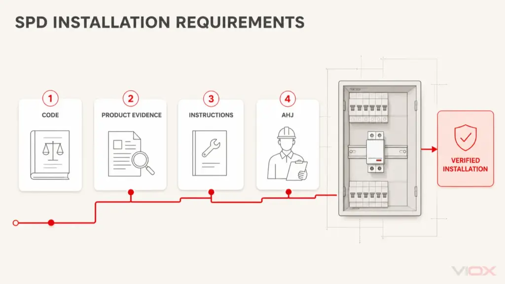
اس صفحے پر
Type 1–Type 2–Type 3 کی ترتیب خود بخود ایک مربوط سرج پروٹیکشن سسٹم نہیں ہوتی۔ یہ لیبلز ٹیسٹ کے فرائض اور ممکنہ اطلاقی کرداروں کی نشاندہی کرتے ہیں؛ یہ اس بات کا ثبوت نہیں دیتے کہ اپ اسٹریم ڈیوائس ڈاؤن اسٹریم ڈیوائس کا بوجھ کم کرے گی، کہ انسٹال شدہ وولٹیج آلات کی برداشت کی حد سے نیچے رہے گا، یا یہ کہ ڈیوائسز کو اضافی ڈیکپلنگ کے بغیر ایک ساتھ لگایا جا سکتا ہے۔.
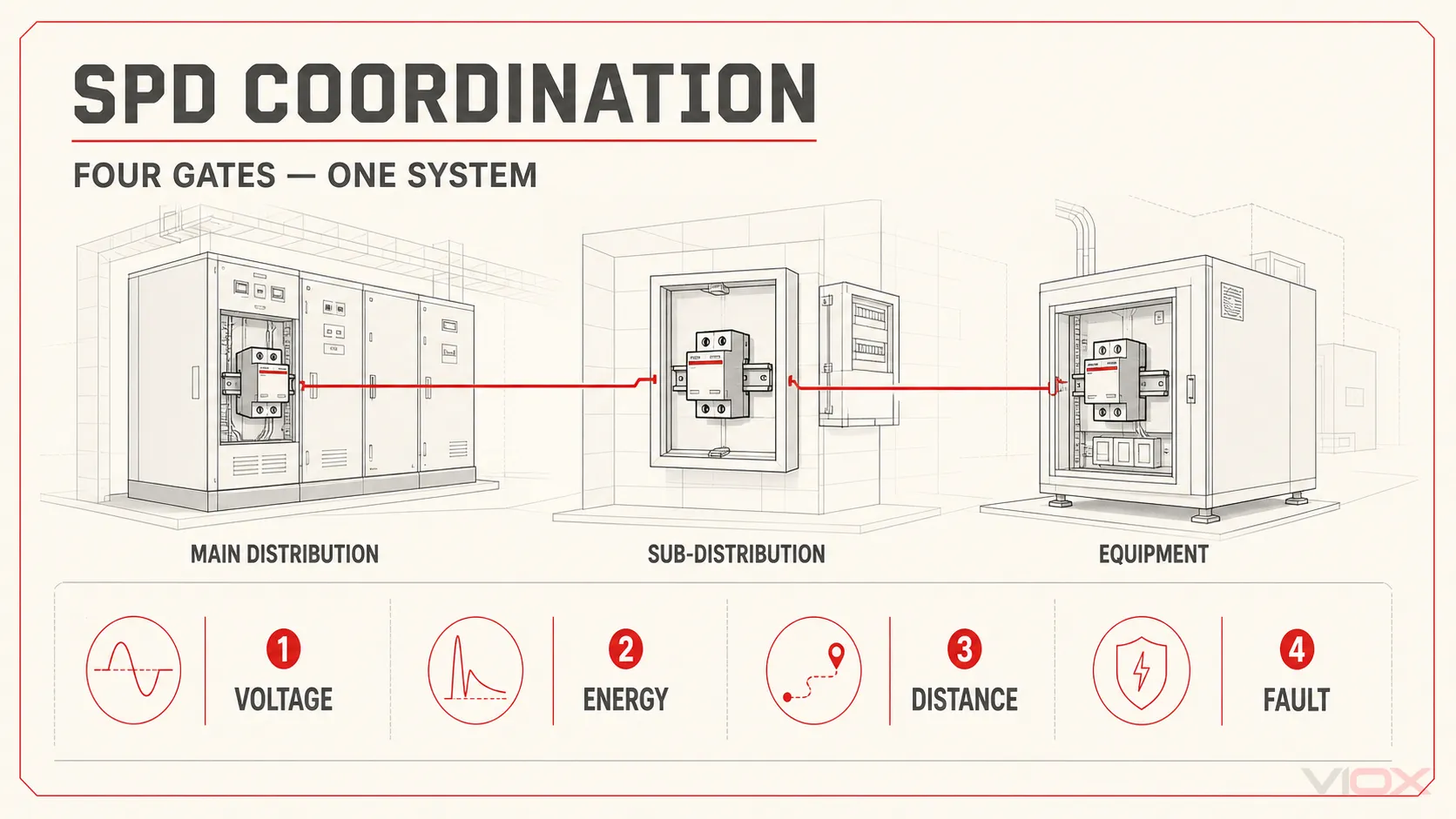
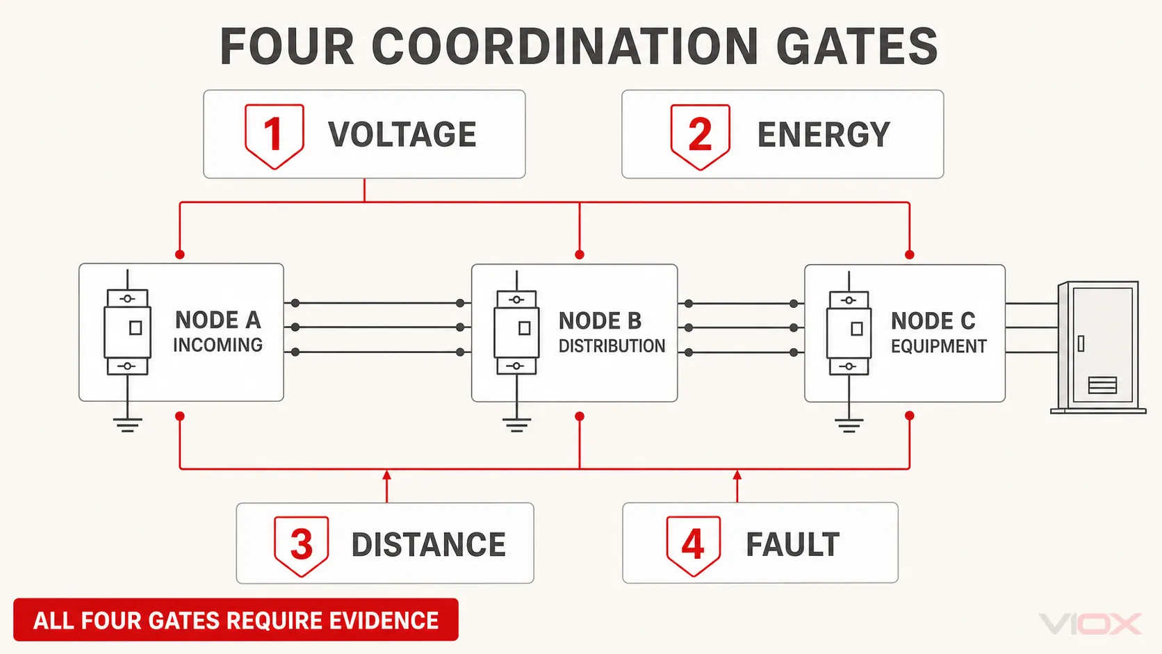
کوآرڈینیشن کو چار الگ الگ تصدیقی گیٹس کے طور پر سمجھیں:
- وولٹیج کوآرڈینیشن: ہر پروٹیکٹڈ نوڈ پر مؤثر وولٹیج کو آلات کی انسولیشن کوآرڈینیشن کے ہدف کے اندر رہنا چاہیے۔.
- انرجی کوآرڈینیشن: ڈاؤن اسٹریم سرج پروٹیکٹو ڈیوائس (SPD) کو اس سے پہلے اوورلوڈ نہیں ہونا چاہیے کہ اپ اسٹریم اسٹیج اس کے لیے مختص کردہ تناؤ کو برداشت کر لے۔.
- فاصلہ اور ڈیکپلنگ: اسٹیجز کے درمیان کنڈکٹرز کا جائزہ ممکنہ ڈیکپلنگ امپیڈینس اور ایسے راستے دونوں کے طور پر لیا جانا چاہیے جو سرج کے نئے خطرے کا باعث بن سکتا ہے۔.
- فالٹ اور بیک اپ پروٹیکشن کوآرڈینیشن: ہر SPD کو متوقع شارٹ سرکٹ کی صورتحال اور اس کے مطلوبہ فیوز، سرکٹ بریکر، یا اندرونی ڈس کنیکٹر کے انتظام کے ساتھ مطابقت رکھنا چاہیے۔.
اگر کسی گیٹ کے لیے درست آلات اور تنصیب کے شواہد موجود نہ ہوں، تو کاسکیڈ کی ابھی تصدیق نہیں ہوئی ہے۔.
کاسکیڈنگ ایک لے آؤٹ ہے؛ کوآرڈینیشن ایک کارکردگی کا دعویٰ ہے
“کاسکیڈنگ” عام طور پر ان حفاظتی مراحل کو بیان کرتی ہے جو ان کمنگ سپلائی سے حساس آلات کی طرف لگائے جاتے ہیں۔ ایک عام تصور یہ ہے کہ ایک اپ اسٹریم لائٹننگ کرنٹ کے قابل اسٹیج، ایک درمیانی ڈسٹری بیوشن لیول اسٹیج، اور لوڈ کے قریب اضافی تحفظ موجود ہو۔.
“کوآرڈینیشن” ایک مشکل سوال پوچھتی ہے: متعلقہ سرج کے تحت وہ اسٹیجز آپس میں کیسے تعامل کریں گے؟
اپ اسٹریم SPD کو اپنی حدود پر تفویض کردہ ہائی اسٹریس (اعلیٰ دباؤ) کا انتظام کرنا چاہیے۔ ڈاؤن اسٹریم SPD کو اپنی ڈیزائن کی گنجائش سے زیادہ کرنٹ یا توانائی حاصل کیے بغیر بقایا خلل کو محدود کرنا چاہیے۔ محفوظ کردہ آلات کو اپنے امپلس ود اسٹینڈ (impulse withstand) کے مطابق وولٹیج دیکھنا چاہیے۔ یہ سب کچھ مزاحمت، انڈکٹنس، کپلنگ اور محدود علیحدگی کے حامل حقیقی کنڈکٹرز کے ذریعے ہونا چاہیے۔.
IEC 61643-12:2020 لو-وولٹیج AC برقی نظاموں سے منسلک SPDs کے انتخاب، آپریشن، مقام، اور کوآرڈینیشن کے اصولوں کا احاطہ کرتا ہے۔. IEC 62305-4:2024 عمارتوں کے اندر برقی اور الیکٹرانک نظاموں کے لیے سسٹم کی سطح پر سرج پروٹیکشن کے اقدامات کو بیان کرتا ہے، جس میں لائٹننگ پروٹیکشن زون کے تصورات اور انڈیوسڈ-وولٹیج کا رویہ شامل ہے۔.
کے لیے وقف گائیڈ ٹائپ 1، ٹائپ 2، اور ٹائپ 3 ایس پی ڈیز وضاحت کرتا ہے کہ ہر درجہ بندی کیا قائم کرتی ہے۔ یہ مضمون ان درجہ بندیوں کے منتخب ہونے کے بعد شروع ہوتا ہے اور یہ سوال اٹھاتا ہے کہ آیا مجوزہ امتزاج ایک سسٹم کے طور پر کام کرتا ہے۔.
سسٹم کو محفوظ نوڈز کے طور پر متعین کریں
خریداری کی فہرست سے شروعات نہ کریں۔ تنصیب کو برقی نوڈز اور حفاظتی حدود کی ترتیب کے طور پر ڈرا کریں۔.
| نوڈ | عام باؤنڈری | کیا معلوم ہونا ضروری ہے | کوآرڈینیشن (مربوط کرنے) کا سوال |
|---|---|---|---|
| اے | ان کمنگ سروس یا مین ڈسٹری بیوشن | سرج کا ماحول، آسمانی بجلی سے تحفظ کا تناظر، سورس اور ارتھنگ کا انتظام، اپ اسٹریم SPD کی ڈیوٹی | کیا یہ مرحلہ ان کمنگ باؤنڈری پر تفویض کردہ دباؤ کو برداشت کر سکتا ہے؟ |
| بی | سب ڈسٹری بیوشن، موٹر کنٹرول سینٹر، یا کنٹرول پینل سپلائی | A سے کیبل کا راستہ، مقامی طور پر پیدا ہونے والی یا کپلڈ سرجز، ڈاؤن اسٹریم SPD کی ریٹنگز | کیا اسٹیج B کو اسٹیج A سے ریلیف ملتا ہے، اور کیا وولٹیج کے مقصد کے لیے اسٹیج B اب بھی ضروری ہے؟ |
| سی | آلات کا ان پٹ یا حتمی محفوظ زون | آلات کی امپلس برداشت کرنے کی صلاحیت، B سے کیبل کا راستہ، بجلی/ڈیٹا کے دیگر داخلے کے راستے، حتمی SPD کی خصوصیات | کیا نصب شدہ تحفظ آلات کے ٹرمینل پر اصل دباؤ کو ڈیزائن کے مقصد کے اندر رکھتا ہے؟ |
یہ نوڈ ماڈل دو عام غلطیوں سے بچاتا ہے۔ اول، مختلف پینلز میں نصب دو ڈیوائسز خود بخود مختلف حفاظتی مراحل نہیں ہوتے اگر وہ مختلف برقی حدود کو کنٹرول نہ کرتے ہوں۔ دوم، آلات ہمیشہ قریب ترین SPD والے ٹرانزینٹ-وولٹیج نوڈ پر نہیں ہوتے۔ کنکشن کنڈکٹرز، بس بارز، کیبل کی علیحدگی، سگنل لائنز، اور بانڈنگ کے راستے ان کے درمیان اضافی وولٹیج پیدا کر سکتے ہیں۔.
فیصلہ کرنے کے لیے تاریں کہاں کہ ایک اسٹیج کا تعلق کہاں سے ہے، الگ استعمال کریں SPD کی تنصیب کی گائیڈ. ۔ کوآرڈینیشن اسٹڈی کا آغاز تب ہوتا ہے جب امیدوار نوڈز کی وضاحت کر دی جاتی ہے۔.
کیسکیڈ (Cascade) چیک کرنے سے پہلے درکار ان پٹس
مصنوعات کا موازنہ کرنے سے پہلے درج ذیل معلومات اکٹھی کریں:
- قابل اطلاق سسٹم اور تنصیب کے معیارات؛;
- AC، DC، فوٹو وولٹک، یا سگنل لائن ایپلی کیشن کی حدود؛;
- سنگل لائن ڈایاگرام اور ارتھنگ کا انتظام؛;
- لائٹننگ پروٹیکشن سسٹم اور لائٹننگ پروٹیکشن زون کی حدود، جہاں لاگو ہو؛;
- ہر مجوزہ پروٹیکشن موڈ کے آر پار برائے نام وولٹیج اور زیادہ سے زیادہ مسلسل وولٹیج؛;
- ہر محفوظ نوڈ پر آلات کے امپلس-ودسٹینڈ یا انسولیشن-کوآرڈینیشن کا مقصد؛;
- SPD کی قسم یا ٹیسٹ کلاس اور ہر مرحلے کے لیے اعلان کردہ ٹیسٹ کی مقداریں؛;
- وولٹیج پروٹیکشن لیول
اوپر, ، ماپا گیا محدود وولٹیج، یا قابل اطلاقVPRمتعلقہ فریم ورک کے تحت ڈیٹا؛; آئی ایم پی,میں,Imax, ، یا دیگر ڈسچارج-کرنٹ کے اعلانات جو مرحلے پر لاگو ہوں؛;- کیبل کی لمبائی، کنڈکٹر کی روٹنگ، لوپ جیومیٹری، اور SPDs اور آلات کے درمیان علیحدگی؛;
- ہر SPD کنکشن پوائنٹ پر متوقع شارٹ سرکٹ کرنٹ؛;
- مطلوبہ بیک اپ فیوز یا سرکٹ بریکر اور قابل اطلاق
ایس سی سی آر,Isccr, ، یا شارٹ سرکٹ کا کوئی اور اعلان؛; - مینوفیکچرر کے کوآرڈینیشن ٹیبلز، ٹیسٹ شدہ کمبی نیشنز، یا درست اپ اسٹریم/ڈاؤن اسٹریم جوڑے کے لیے ایپلی کیشن کی ہدایات۔.
یہ ان پٹس ایک دوسرے کے متبادل نہیں ہیں۔ ایک بڑا Imax کم انسٹال شدہ حفاظتی وولٹیج کو ثابت نہیں کرتا۔ ایک کم کیٹلاگ اوپر یہ ثابت نہیں کرتا کہ فائنل اسٹیج SPD موصول ہونے والی توانائی کو برداشت کر سکتا ہے۔ ایک چھوٹی کیبل توانائی کے کوآرڈینیشن کو ثابت نہیں کرتی۔ ہر آئٹم ایک مختلف گیٹ کو بند کرتا ہے۔.
گیٹ 1: ہر نوڈ پر وولٹیج کوآرڈینیشن کی تصدیق کریں
کیسکیڈ کا مقصد تین ڈیٹا شیٹس پر بتدریج چھوٹے نمبر پیدا کرنا نہیں ہے۔ اس کا مقصد محفوظ کردہ آلات پر ظاہر ہونے والے وولٹیج کو موصلیت کے کوآرڈینیشن (insulation-coordination) کے طے شدہ ہدف کے اندر رکھنا ہے۔.
ایک مفید تصوراتی جانچ یہ ہے:
آلات پر نصب حفاظتی وولٹیج < آلات کے امپلس برداشت کرنے کا ہدفبائیں جانب ہمیشہ SPD پر چھپے ہوئے کے برابر نہیں ہوتی اوپر. ۔ اس میں شامل ہو سکتا ہے:
- متعلقہ پروٹیکشن موڈ اور امپلس کے لیے SPD کا بقایا یا محدود وولٹیج؛;
- SPD تک اور وہاں سے سرج کرنٹ لے جانے والے کنڈکٹرز میں انڈکٹیو وولٹیج؛;
- SPD کنکشن پوائنٹ اور آلات کے ٹرمینلز کے درمیان وولٹیج کا فرق؛;
- قریبی کنڈکٹرز یا دیگر سروسز سے کپلنگ؛;
- طویل راستوں پر آسیلیشن یا لہروں کے پھیلاؤ کے اثرات؛;
- غیر مربوط سگنل، ڈیٹا، اینٹینا، کنٹرول، یا بانڈنگ پاتھ کے ذریعے داخل ہونے والا تناؤ۔.
اس کا تعلق تنصیب پر منحصر ہے۔ اپنی مرضی سے کوئی فیصد شامل نہ کریں اور نہ ہی کوئی ایک عالمی “وولٹ فی میٹر” فیکٹر استعمال کریں۔ پروجیکٹ کے لیے قابل اطلاق تنصیب کا طریقہ، مینوفیکچرر کی ہدایات، اور انجینئرنگ ماڈل استعمال کریں۔.
اسی طرح، شامل نہ کریں اوپر اپ اسٹریم اور ڈاؤن اسٹریم SPDs کی اقدار۔ یہ سیریز وولٹیج ڈراپس نہیں ہیں۔ ہر قدر بیان کردہ ٹیسٹ کے حالات کے تحت کسی ڈیوائس یا پروٹیکشن موڈ کو بیان کرتی ہے۔ کاسکیڈ کا جائزہ اس نوڈ پر لیا جانا چاہیے جہاں آلات منسلک ہیں۔.
مسلسل وولٹیج ریٹنگ اور پروٹیکشن لیول کے درمیان فرق کے لیے، ملاحظہ کریں SPD Uc اور Up گائیڈ. ۔ حتمی انتخاب میں مخصوص موڈ کی درست اقدار کا استعمال کیا جانا چاہیے جو کہ SPD ڈیٹا شیٹ.
وولٹیج گیٹ کا ثبوت
گیٹ 1 کو صرف تب پاس شدہ نشان زد کریں جب ڈیزائن ریکارڈ درج ذیل کی نشاندہی کرے:
- آلات کی برداشت کا مقصد؛;
- آلات کے ٹرمینلز پر متعلقہ سرج موڈز؛;
- قابل اطلاق SPD پروٹیکشن لیول کا اعلان؛;
- تنصیب شدہ کنکشن اور علیحدگی کے اثرات؛;
- قابل اطلاق معیار یا ڈیزائن کے اصول سے درکار کوآرڈینیشن مارجن یا طریقہ۔.
اگر آلات کی برداشت معلوم نہ ہو، تو ایک نچلا اوپر سمتی لحاظ سے مفید ہے لیکن تصدیق کا عمل مکمل نہیں کر سکتا۔.
گیٹ 2: مراحل کے درمیان انرجی کوآرڈینیشن کی تصدیق کریں
ڈاؤن اسٹریم SPD کو عام طور پر آنے والے مرحلے کی نسبت کم شدید دباؤ کے لیے ڈیزائن کیا جاتا ہے۔ اسے اس طرح ردعمل ظاہر نہیں کرنا چاہیے کہ یہ اپ اسٹریم مرحلے کے اپنا مطلوبہ کام انجام دینے سے پہلے سرج کا تباہ کن حصہ برداشت کر لے۔.
انرجی کوآرڈینیشن کا انحصار ڈیوائسز اور ان کے درمیان موجود نیٹ ورک کے مکمل وولٹیج-کرنٹ-ٹائم رویے پر ہوتا ہے۔ متعلقہ عوامل میں شامل ہیں:
- وولٹیج-سوئچنگ یا وولٹیج-لمٹنگ رویہ؛;
- قابل اطلاق امپلس کے تحت متحرک بقایا کرنٹ (residual voltage)؛;
- ردعمل اور کمیوٹیشن کا رویہ؛;
- کرنٹ ویوفارم اور چارج؛;
- ڈاؤن اسٹریم اسٹیج کی انرجی ودہولڈ (energy withstand)؛;
- اسٹیجز کے درمیان کنڈکٹر کی رکاوٹ (impedance)؛;
- ماخذ کی خصوصیات اور کرنٹ کی تقسیم؛;
- مشترکہ ڈیوائسز کے اندرونی ہم آہنگی۔.
یہی وجہ ہے کہ “Type 1 اپ اسٹریم، Type 2 ڈاؤن اسٹریم” کافی ثبوت نہیں ہے۔ Type 1 ڈیوائسز میں استعمال ہونے والی ٹیکنالوجیز مختلف طریقے سے برتاؤ کر سکتی ہیں، اور ایک جیسے لیبل والی ڈاؤن اسٹریم ڈیوائسز کی خصوصیات مختلف ہو سکتی ہیں۔.
Phoenix Contact کی سرج پروٹیکشن تکنیکی رہنمائی میں کہا گیا ہے کہ Type 2 SPDs کو اپ اسٹریم Type 1 SPDs کے ساتھ مربوط ہونا چاہیے اور تمام Type 1 ٹیکنالوجیز کے لیے کوئی عمومی قابل اطلاق کوآرڈینیشن کی شرط موجود نہیں ہے۔ DEHN انرجی کوآرڈینیشن کی تعریف کاسکیڈڈ حفاظتی عناصر کے درمیان منتخب تعامل کے طور پر کرتا ہے اور خبردار کرتا ہے کہ اگر اپ اسٹریم اسٹیج اسے بہت دیر سے یا ناکافی طور پر ریلیف فراہم کرے تو ڈاؤن اسٹریم SPD تباہ ہو سکتا ہے۔.
ثبوت کی مضبوط ترین شکلیں
درج ذیل درجہ بندی کا استعمال کریں:
- ایک مینوفیکچرر کوآرڈینیشن ٹیبل جس میں اپ اسٹریم اور ڈاؤن اسٹریم کے درست ماڈلز کے نام درج ہوں؛;
- ایک ٹیسٹ شدہ سسٹم یا ایپلیکیشن رپورٹ جو مجوزہ امتزاج اور تنصیب کے متعلقہ حالات کا احاطہ کرتی ہو؛;
- مینوفیکچرر کی طرف سے منظور شدہ مشترکہ Type 1+2 یا Type 2+3 اسمبلی جس میں اندرونی کوآرڈینیشن کا اعلان کیا گیا ہو؛;
- مناسب ڈیوائس ماڈلز اور امپلس حالات کا استعمال کرتے ہوئے ایک انجینئرنگ اسٹڈی یا سسٹم کی سطح کا ٹیسٹ۔.
“صرف ”ایک ہی برانڈ" ہونا ثبوت نہیں ہے۔ کوآرڈینیشن ٹیبل صرف مخصوص پروڈکٹ فیملیز، ریٹنگز، پروٹیکشن موڈز، کنڈکٹر کے انتظامات، یا کم از کم فاصلوں کا احاطہ کر سکتا ہے۔ اس کے برعکس، مختلف برانڈز کا امتزاج خود بخود ناممکن نہیں ہے، لیکن اس کے لیے ایسے ثبوت کی ضرورت ہوتی ہے جس کا اندازہ صرف کیٹلاگ کے Type لیبلز اور kA ویلیوز کا موازنہ کر کے نہیں لگایا جا سکتا۔.
انرجی-گیٹ اسٹاپ رول
اگر ڈیوائس کا درست جوڑا ٹیسٹ شدہ کوآرڈینیشن ڈیٹا میں شامل نہیں ہے اور کوئی مستند انجینئرنگ تصدیق دستیاب نہیں ہے، تو گیٹ 2 کو درج ذیل کے طور پر ریکارڈ کریں ثبوت موجود نہیں. ۔ توانائی کی تقسیم کا اندازہ ان Imax تناسب سے نہ لگائیں اور نہ ہی یہ فرض کریں کہ زیادہ kA نمبر والا آلہ ہمیشہ پہلے کرنٹ گزارے گا۔.
گیٹ 3: فاصلے کے دو کرداروں کو سمجھنا
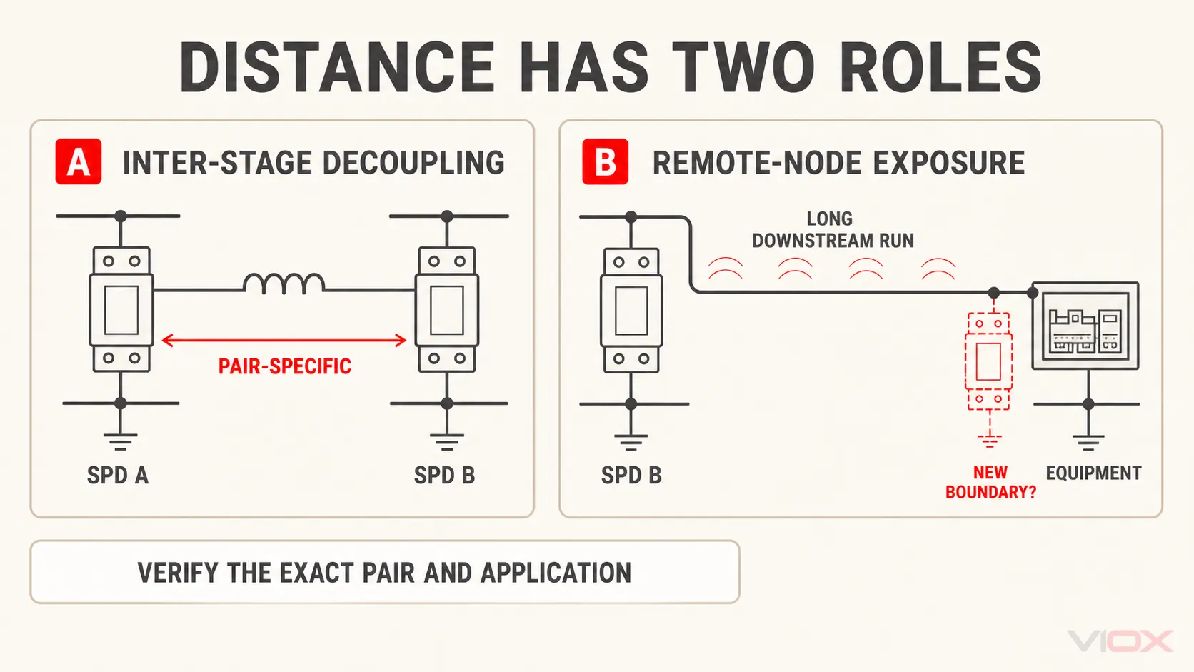
فاصلہ سرج پروٹیکشن کی رہنمائی میں دو مختلف وجوہات کی بنا پر ظاہر ہوتا ہے۔ ان کو ملانے سے متضاد اصول پیدا ہوتے ہیں۔.
کردار A: مراحل کے درمیان امپیڈینس ڈی کپلنگ فراہم کر سکتی ہے
ایک اپ اسٹریم اور ڈاؤن اسٹریم SPD کے درمیان کنڈکٹرز میں تیز امپلس کے دوران امپیڈینس ہوتی ہے۔ کچھ مربوط انتظامات میں، وہ امپیڈینس وولٹیج کا وہ فرق پیدا کرنے میں مدد کرتی ہے جو اپ اسٹریم اور ڈاؤن اسٹریم مراحل کے لیے ضروری ہے تاکہ وہ منتخب طور پر کام کر سکیں یا ردعمل دے سکیں۔.
اس لیے پرانی یا پروڈکٹ سے مخصوص رہنمائی خاص آلات کے درمیان کم از کم کنڈکٹر کی لمبائی تجویز کر سکتی ہے۔ جب دستیاب کنڈکٹر کی لمبائی بہت کم ہو تو مینوفیکچرر اس کے بجائے ڈی کپلنگ عنصر کی وضاحت کر سکتا ہے۔.
یہ ضرورت اس سے تعلق رکھتی ہے مخصوص SPD جوڑا. مثال کے طور پر، ABB نے پروڈکٹ فیملی کوآرڈینیشن ٹیبلز شائع کیے ہیں جن میں مختلف Type 1/Type 2 اور Type 2/Type 2 کے امتزاج کے لیے کم از کم فاصلے دیے گئے ہیں۔ یہ فاصلے درج شدہ ABB امتزاجات کے لیے ثبوت ہیں—نہ کہ تمام SPDs کے لیے عالمگیر فاصلاتی اصول۔.
جدید مربوط مصنوعات کو ایک دوسرے کے ساتھ نصب کیا جا سکتا ہے جب ان کا اندرونی رویہ اور ٹیسٹ شدہ امتزاج کسی ڈی کپلنگ رن (decoupling run) کا تقاضا نہ کرے۔ “کسی کم از کم فاصلے کی ضرورت نہیں” بھی ایک ماڈل جوڑے کا دعویٰ ہے، نہ کہ تمام Type 1+Type 2 انتظامات کی عمومی خصوصیت۔.
کردار B: ایک طویل ڈاؤن اسٹریم رن تحفظ کی ایک نئی ضرورت پیدا کر سکتا ہے
ڈسٹری بیوشن SPD اور آلات کے درمیان ایک لمبی کیبل ریموٹ نوڈ کو انڈیوسڈ وولٹیج، اوسلیشن، کپلنگ، یا سرج کے داخلے کے کسی اور راستے سے دوچار کر سکتی ہے۔ اس لیے تنصیبی اصول اور مینوفیکچرر کی ایپلیکیشن گائیڈز آلات کے قریب یا کسی نئی زون باؤنڈری پر ایک اور SPD کا مطالبہ کر سکتی ہیں جب فاصلہ بیان کردہ شرط سے تجاوز کر جائے۔.
اکثر حوالہ دی جانے والی 10 m کی قدر مخصوص اطلاق اور معیارات کے سیاق و سباق میں ظاہر ہوتی ہے، لیکن اسے درج ذیل غلط اصولوں میں سے کسی میں تبدیل نہیں کیا جانا چاہیے:
- “دو SPDs اس وقت مربوط ہوتے ہیں جب وہ 10 m کے فاصلے پر ہوں۔”
- “10 m سے زیادہ دور موجود کسی بھی آلات کو ہمیشہ اسی اضافی SPD کی ضرورت ہوتی ہے۔”
ایک اصول کا تعلق تعامل سے ہے تحفظ کے مراحل کے درمیان; ؛ دوسرا تعلق وولٹیج کے ایکسپوژر سے ہے ایک دور دراز محفوظ نوڈ پر. ۔ درست معیار، قومی اختیار، سسٹم لے آؤٹ، اور مینوفیکچرر کی ہدایات کا اطلاق کریں۔.
ڈسٹنس گیٹ ورک شیٹ
نوڈز کے ہر جوڑے کے لیے، درج ذیل ریکارڈ کریں:
| چیک | درکار ثبوت | پاس ہونے کی شرط |
|---|---|---|
| انٹر اسٹیج علیحدگی | کنڈکٹر کی اصل روٹ کردہ لمبائی اور جیومیٹری | مخصوص جوڑے کی کوآرڈینیشن ہدایات یا منظور شدہ ڈیکپلنگ ڈیزائن سے مطابقت رکھتا ہے |
| ریموٹ نوڈ ایکسپوزر | کیبل روٹ، کپلنگ کا ماحول، زون کی حد اور آلات کا مقام | جب قابل اطلاق ڈیزائن کا طریقہ کار تقاضا کرے تو اضافی تحفظ فراہم کیا جاتا ہے |
| SPD کنکشن کا راستہ | ہر SPD کے لیے مکمل سرج کرنٹ لوپ | روٹنگ مینوفیکچرر کی زیادہ سے زیادہ لمبائی اور لے آؤٹ کی ہدایات کے مطابق ہے۔ |
| دیگر سروسز | پاور، ڈیٹا، کنٹرول، اینٹینا اور بانڈنگ کے راستے | ہر کنڈکٹیو انٹری پاتھ کو ایک ہی پروٹیکشن باؤنڈری پر مربوط کیا گیا ہے۔ |
مخصوص SPD وائرنگ گائیڈ کنکشن پاتھ کے نفاذ کا احاطہ کرتا ہے۔ یہ صفحہ ان راستوں کو صرف کوآرڈینیشن ان پٹ کے طور پر استعمال کرتا ہے۔.
گیٹ 4: سرج-انرجی کوآرڈینیشن کو فالٹ کوآرڈینیشن سے الگ رکھیں
ایک SPD مائیکرو سیکنڈز کے لیے سرج کرنٹ کو کنڈکٹ کر سکتا ہے اور اگر کوئی اندرونی جزو یا ڈس کنیکٹر ناکام ہو جائے تو یہ پاور-فریکوئنسی فالٹ بن سکتا ہے۔ لہذا سسٹم کو SPD کو متوقع شارٹ سرکٹ کی حالت اور اس کے لیے درکار بیک اپ پروٹیکشن کے ساتھ مربوط کرنا چاہیے۔.
یہ جانچ SPD-to-SPD انرجی کوآرڈینیشن سے متعلق ہے—لیکن اس کے مساوی نہیں ہے۔.
| کوآرڈینیشن کا مسئلہ | زیر غور خلل | ثبوت |
|---|---|---|
| SPD-to-SPD انرجی کوآرڈینیشن | آسمانی بجلی یا سوئچنگ امپلس | درست کاسکیڈ ٹیبل، ٹیسٹ شدہ جوڑا، ایپلیکیشن رپورٹ، یا سسٹم اسٹڈی |
| SPD پروٹیکشن لیول کوآرڈینیشن | محفوظ شدہ نوڈ پر ٹرانزینٹ وولٹیج | اوپر یا محدود وولٹیج کا ڈیٹا، آلات کی برداشت، تنصیب کے اثرات |
| SPD اور بیک اپ پروٹیکشن کے درمیان ہم آہنگی | SPD کے کام کرنے/ناکام ہونے کے بعد پاور فریکوئنسی شارٹ سرکٹ یا فالو کرنٹ کی صورتحال | مینوفیکچرر کا بیک اپ فیوز/بریکر ٹیبل،, ایس سی سی آر, Isccr, Ifi, ، جہاں لاگو ہو فالٹ کرنٹ کا مطالعہ |
| اپ اسٹریم حفاظتی ڈیوائس کی سلیکٹیوٹی | فالٹ کے دوران سروس کا تسلسل | قابل اطلاق فریم ورک کے تحت حفاظتی ڈیوائس کی کوآرڈینیشن کا مطالعہ |
کسی بھی بیک اپ بریکر کے انتخاب کی اجازت کے طور پر SPD انرجی کوآرڈینیشن ٹیبل کا استعمال نہ کریں۔ اس بات کے ثبوت کے طور پر کہ دو SPDs امپلس انرجی کو درست طریقے سے شیئر کرتے ہیں، بریکر کاسکیڈنگ یا سلیکٹیوٹی ٹیبل کا استعمال نہ کریں۔.
گیٹ 4 صرف تب پاس ہوتا ہے جب ہر نصب شدہ SPD کے اپنے کنکشن پوائنٹ پر شارٹ سرکٹ اور منقطع کرنے کا ایک منظور شدہ انتظام موجود ہو۔ اگر کسی بیرونی بیک اپ فیوز یا بریکر کی ضرورت ہو تو، کرنٹ کے سائز کے عمومی اصول کے بجائے مینوفیکچرر کے منظور شدہ ڈیوائس اور ریٹنگ رینج کا ہی استعمال کریں۔.
فور-گیٹ کوآرڈینیشن ورک شیٹ
ہر SPD اسٹیج اور اس کے زیر تحفظ آلات کے لیے ایک قطار مکمل کریں۔.
| فیلڈ | اسٹیج A: ان کمنگ | اسٹیج B: ڈسٹری بیوشن | اسٹیج C: آلات |
|---|---|---|---|
| درست SPD مینوفیکچرر اور ماڈل | |||
| پروڈکٹ کا معیار اور قسم/ٹیسٹ کلاس | |||
| تحفظ کے طریقے | |||
یو سی/MCOV اور TOV کی حد |
|||
اوپر/موڈ کے لحاظ سے محدود وولٹیج کا اعلان |
|||
قابل اطلاق آئی ایم پی, میں, Imax، یا Uoc |
|||
| محفوظ کردہ آلات اور برداشت کا مقصد | |||
| انسٹال شدہ کنکشن کا راستہ | |||
| اوپر/نیچے کے مرحلے تک کا فاصلہ | |||
| جوڑے سے متعلقہ کوآرڈینیشن کا ثبوت | |||
| متوقع شارٹ سرکٹ کی حالت | |||
| مطلوبہ بیک اپ تحفظ | |||
| گیٹ کا نتیجہ اور غیر حل شدہ شواہد |
پھر مکمل کاسکیڈ کے لیے ایک نتیجہ جاری کریں:
- کامیاب: ہر مرحلے اور پروٹیکشن موڈ کے لیے چاروں گیٹس معاون ہیں۔.
- مشروط: آرکیٹیکچر قابلِ فہم ہے، لیکن نامزد شواہد یا انجینئرنگ کا حساب کتاب ابھی باقی ہے۔.
- ناکام: ایک مرحلہ وولٹیج کے ہدف سے تجاوز کر سکتا ہے، ڈاون اسٹریم SPD کو اوورلوڈ کر سکتا ہے، اسپیسنگ/ڈی کپلنگ کی ہدایات کی خلاف ورزی کر سکتا ہے، یا قابل قبول فالٹ پروٹیکشن کی کمی کا شکار ہو سکتا ہے۔.
مینوفیکچرر کوآرڈینیشن کا خالی فیلڈ کوئی انتظامی تفصیل نہیں ہے۔ یہ ایک غیر حل شدہ تکنیکی ان پٹ ہے۔.
کام کی گئی تصوراتی مثال: مین بورڈ سے PLC کیبنٹ تک
ایک صنعتی تنصیب پر غور کریں جس میں:
- مین ڈسٹری بیوشن بورڈ پر ایک آنے والا SPD؛;
- ڈاون اسٹریم ڈسٹری بیوشن پینل پر دوسرا SPD؛;
- پروگرامیبل لاجک کنٹرولر (PLC) کیبنٹ پر ایک حتمی SPD؛;
- کیبنٹ میں داخل ہونے والی پاور اور ڈیٹا کیبلز موجود ہوں۔.
درست جائزہ تین مراحل کے لیے من مانی kA اقدار تفویض کرنے سے شروع نہیں ہوتا۔.
- سب سے پہلے Node C کی وضاحت کریں۔. PLC پاور ان پٹ امپلس ود اسٹینڈ (impulse withstand) اور منسلک کمیونیکیشن پورٹس کے ود اسٹینڈ کو ریکارڈ کریں۔ ہر موصل داخلی راستے کی نشاندہی کریں۔.
- حتمی SPD کو چیک کریں۔. اس کے پروٹیکشن موڈز، وولٹیج ریٹنگ، لمیٹنگ وولٹیج ڈیٹا، ڈسچارج ڈیوٹی، اور اس کے کنکشن پاتھ کے ذریعے شامل ہونے والے وولٹیج کی تصدیق کریں۔.
- B-to-C رن کا جائزہ لیں۔. فیصلہ کریں کہ آیا لمبائی اور روٹنگ ایک نئی پروٹیکشن باؤنڈری یا انڈیوسڈ وولٹیج کا خطرہ پیدا کرتی ہے۔ تصدیق کریں کہ آیا قابل اطلاق ڈیزائن کے طریقہ کار کے تحت حتمی SPD کی ضرورت ہے۔.
- اسٹیج B سے اسٹیج C کے انرجی کوآرڈینیشن کی تصدیق کریں۔. ایک ایسی ٹیبل یا ٹیسٹ ریکارڈ حاصل کریں جو درست جوڑے اور نصب شدہ علیحدگی کا احاطہ کرتا ہو۔ اگر آلات مختلف مینوفیکچررز کے ہوں، تو واضح مطابقت کا ثبوت طلب کریں یا مناسب مطالعہ کریں۔.
- اس عمل کو اسٹیج A سے اسٹیج B کے لیے دہرائیں۔. ان کمنگ اسٹیج مختلف پروٹیکشن ٹیکنالوجی استعمال کر سکتا ہے، لہذا ڈسٹری بیوشن SPD کے ساتھ اس کا تعامل الگ ثبوت کا متقاضی ہے۔.
- ہر پینل پر گیٹ 4 کو بند کریں۔. ممکنہ شارٹ سرکٹ کرنٹ اور بیک اپ پروٹیکشن کی ضرورت A، B، اور C پر مختلف ہو سکتی ہے۔.
- ڈیٹا لائنز کو مربوط کریں۔. صرف پاور لائن پروٹیکشن، PLC پاور پورٹ اور غیر محفوظ کمیونیکیشن پورٹ کے درمیان ظاہر ہونے والے وولٹیج کو کنٹرول نہیں کر سکتی۔.
مثال تب ہی مکمل ہوتی ہے جب آلات کی برداشت، نصب شدہ وولٹیج پاتھ، جوڑے کی مطابقت، اور فالٹ پروٹیکشن کے ثبوت دستاویزی شکل میں موجود ہوں۔ صرف ڈیوائس ٹائپ کے لیبلز چاروں سوالات کو غیر حل شدہ چھوڑ دیتے ہیں۔.
مشترکہ SPD اور مختلف برانڈز کے کیسکیڈز
کیا Type 1+2 ڈیوائس ڈاؤن اسٹریم Type 2 SPD کی ضرورت کو ختم کرتی ہے؟
خود بخود نہیں۔ ایک مشترکہ ڈیوائس یہ ثابت کرتی ہے کہ اسمبلی میں اعلان کردہ Type 1 اور Type 2 ٹیسٹ کی ذمہ داریاں موجود ہیں۔ آیا کسی اور مرحلے کی ضرورت ہے یا نہیں، اس کا انحصار پروٹیکٹڈ نوڈ وولٹیج کے ہدف، کیبل کے راستے، آلات کے مقام، سرج کے دیگر راستوں، اور مشترکہ ڈیوائس کی ایپلی کیشن گائیڈنس پر ہے۔.
کیا Type 1 اور Type 2 SPD کو ساتھ ساتھ نصب کیا جا سکتا ہے؟
جی ہاں، جب درست امتزاج کو ساتھ ساتھ تنصیب کے لیے ڈیزائن اور دستاویزی شکل دی گئی ہو۔ اگر کوآرڈینیشن کی ہدایات میں کنڈکٹر کو الگ کرنے یا ڈی کپلنگ عنصر کا ذکر ہو، تو اس انتظام کے بغیر ساتھ ساتھ تنصیب کی تصدیق نہیں ہوتی۔.
کیا مختلف مینوفیکچررز کے SPD کو کیسکیڈ کیا جا سکتا ہے؟
صرف مناسب مطابقت کے ثبوت کے ساتھ۔ یو سی, اوپر, ، Type، اور kA کی اقدار کو ملانا ڈیوائسز کے متحرک تعامل (dynamic interaction) کو دوبارہ پیدا نہیں کرتا۔ ٹیسٹ شدہ امتزاج، باہمی طور پر قبول شدہ ایپلی کیشن ڈیٹا، یا انجینئرنگ اسٹڈی کی درخواست کریں۔.
مربوط SPD سیٹ کے لیے RFQ چیک لسٹ
جب مربوط حل کی درخواست کی جائے تو درج ذیل فراہم کریں:
- مکمل سنگل لائن ڈایاگرام اور ارتھنگ کا انتظام؛;
- نظام کے وولٹیجز اور آپریٹنگ ٹالرنس؛;
- آسمانی بجلی سے تحفظ اور زون کی حدود کی معلومات؛;
- تحفظ کے مراحل کے درمیان کیبل کی لمبائی اور روٹنگ؛;
- آلات کے امپلس برداشت کرنے کے اہداف؛;
- ہر نوڈ پر درکار تحفظ کے موڈز؛;
- ہر کنکشن پوائنٹ پر متوقع شارٹ سرکٹ کرنٹ؛;
- تجویز کردہ اپ اسٹریم اور ڈاؤن اسٹریم ماڈل نمبرز؛;
- مطلوبہ بیک اپ پروٹیکشن اور آئسولیشن کا طریقہ؛;
- ہر باؤنڈری کو عبور کرنے والے تمام پاور، سگنل، ڈیٹا، اور کنٹرول انٹرفیس۔.
جواب میں درخواست:
- مصنوعات کی درست ڈیٹا شیٹ اور تنصیب کی ہدایات؛;
- جوڑے کے لیے مخصوص انرجی کوآرڈینیشن ٹیبل یا ٹیسٹ کے شواہد؛;
- اجازت یافتہ علیحدگی یا ڈی کپلنگ کے تقاضے؛;
- موڈ کے لحاظ سے وولٹیج سے تحفظ کا ڈیٹا؛;
- شارٹ سرکٹ اور بیک اپ پروٹیکشن کے اعلانات؛;
- مشترکہ ڈیوائس کا دائرہ کار جہاں Type 1+2 یا Type 2+3 تجویز کیا گیا ہو؛;
- مخلوط فیملی یا مخلوط برانڈ کے امتزاج کے لیے تحریری تصدیق۔.
سسٹم کی ضروریات طے ہونے کے بعد، موازنہ کریں VIOX SPD رینج اور نوڈ ورک شیٹ جمع کروائیں [email protected] ماڈل کی سطح کی دستاویزات کے لیے۔ پروڈکٹ فیملی کی مماثلت درست کوآرڈینیشن کے ثبوت کا متبادل نہیں ہے۔.
حتمی کوآرڈینیشن رول
ایک قابل دفاع SPD کاسکیڈ کا مطلب یہ نہیں ہے کہ “مین بورڈ پر زیادہ kA اور آگے کی طرف کم kA ہو۔” یہ ایک دستاویزی نظام ہے جس میں:
- ہر مرحلے کی ایک متعین حفاظتی حد ہوتی ہے؛;
- نصب شدہ وولٹیج آلات کی برداشت کے ہدف کے ساتھ مطابقت رکھتی ہے؛;
- اوپر اور نیچے کی طرف موجود ڈیوائسز متعلقہ امپلس (impulses) کے لیے انرجی کے لحاظ سے مربوط (energy-coordinated) ہوتی ہیں؛;
- فاصلہ، کنڈکٹر کی روٹنگ، اور دیگر سروس انٹریز شامل ہوتی ہیں؛;
- ہر SPD کے پاس قابل قبول شارٹ سرکٹ اور بیک اپ پروٹیکشن موجود ہوتی ہے؛;
- مطابقت کا ثبوت بالکل انہی ڈیوائسز اور ترتیب پر لاگو ہوتا ہے۔.
اگر ان میں سے کسی ایک بیان کو ثابت نہ کیا جا سکے، تو کاسکیڈ کو مشروط سمجھیں—مربوط نہیں۔.
تکنیکی حوالہ جات
- IEC 61643-12:2020 — لو وولٹیج AC SPDs کے لیے انتخاب اور اطلاق کے اصول
- IEC 62305-4:2024 — ڈھانچوں کے اندر برقی اور الیکٹرانک نظام
- IEC 61643-01:2024 — لو-وولٹیج SPDs کے لیے عمومی تقاضے اور ٹیسٹ کے طریقے
- IEC 61643-11:2025 — AC لو-وولٹیج پاور سسٹمز سے منسلک SPDs
- Phoenix Contact — آسمانی بجلی اور سرج پروٹیکشن کی بنیادی باتیں
- DEHN — انرجی کوآرڈینیشن کی اصطلاحات اور اطلاق کی رہنمائی
- ABB — سرج پروٹیکٹو ڈیوائسز کے لیے کوآرڈینیشن کا اصول
- Schneider Electric — سرج پروٹیکٹو ڈیوائسز کی کوآرڈینیشن
یہ مضمون سسٹم کے انتخاب اور شواہد کا ایک فریم ورک فراہم کرتا ہے، نہ کہ یہ کسی پروجیکٹ پروٹیکشن اسٹڈی، پروڈکٹ کی ہدایات، یا قابل اطلاق تنصیبی قواعد کا متبادل ہے۔ تنصیب اور بجلی کے ساتھ کام، سائٹ کے منظور شدہ برقی حفاظتی طریقہ کار کے تحت اہل عملے کے ذریعے انجام دیا جانا چاہیے۔.