
صنعتی آٹومیشن کے لیے کنٹرول پینلز ڈیزائن کرتے وقت، انٹرفیس ریلے ماڈیولز اور اسٹینڈرڈ پی سی بی ریلے کے درمیان انتخاب نظام کی وشوسنییتا، دیکھ بھال کے اخراجات اور طویل مدتی کارکردگی پر نمایاں اثر ڈال سکتا ہے۔ انٹرفیس ریلے ماڈیولز بلٹ ان پروٹیکشن سرکٹس اور DIN-ریل ماؤنٹنگ کے ساتھ پلگ اینڈ پلے انسٹالیشن پیش کرتے ہیں، جو انہیں ہائی ڈینسٹی پینلز کے لیے مثالی بناتے ہیں جن میں بار بار دیکھ بھال کی ضرورت ہوتی ہے۔ اسٹینڈرڈ پی سی بی ریلے ہائی والیوم پروڈکشن کے لیے لاگت سے موثر حل فراہم کرتے ہیں جہاں جگہ کم محدود ہوتی ہے اور تبدیلی کے چکر قابل پیش گوئی ہوتے ہیں۔ فیصلہ بالآخر آپ کی ایپلیکیشن کی سوئچنگ فریکوئنسی، ماحولیاتی حالات، پینل کی جگہ کی رکاوٹوں اور دیکھ بھال کی رسائی کی ضروریات پر منحصر ہے۔.
کلیدی ٹیک ویز
- انٹرفیس ریلے ماڈیولز پروٹیکشن سرکٹس، ایل ای ڈی انڈیکیٹرز اور معیاری ساکٹ کو مربوط کرتے ہیں، جو مجرد پی سی بی ریلے اسمبلیوں کے مقابلے میں تنصیب کے وقت کو 40% تک کم کرتے ہیں۔
- اسٹینڈرڈ پی سی بی ریلے فی یونٹ 30-50% کم لاگت آتی ہے لیکن اضافی اجزاء (ڈائیوڈس، ریزسٹرس، انڈیکیٹرز) اور کسٹم پی سی بی ڈیزائن کی ضرورت ہوتی ہے۔
- برقی تنہائی نمایاں طور پر مختلف ہے: انٹرفیس ماڈیولز عام طور پر آپٹوکوپلرز کے ذریعے 4-6kV آئسولیشن فراہم کرتے ہیں، جبکہ بنیادی پی سی بی ریلے صرف ریلے کی کوائل سے رابطہ کی موروثی آئسولیشن (عام طور پر 4kV) پیش کرتے ہیں۔
- بحالی کی رسائی پلگ ان انٹرفیس ماڈیولز کے ساتھ بہتر ہے—تکنیکی ماہرین ملحقہ وائرنگ میں خلل ڈالے بغیر 60 سیکنڈ سے بھی کم وقت میں ناکام ریلے کو تبدیل کر سکتے ہیں۔
- IEC 61810-1 تعمیل صنعتی انٹرفیس ماڈیولز کے لیے معیاری ہے، جو درجہ حرارت کی حدود (-40°C سے +70°C) اور ارتعاش کے حالات میں مستقل کارکردگی کو یقینی بناتا ہے۔
بنیادی اختلافات کو سمجھنا
انٹرفیس ریلے ماڈیول کیا ہے؟
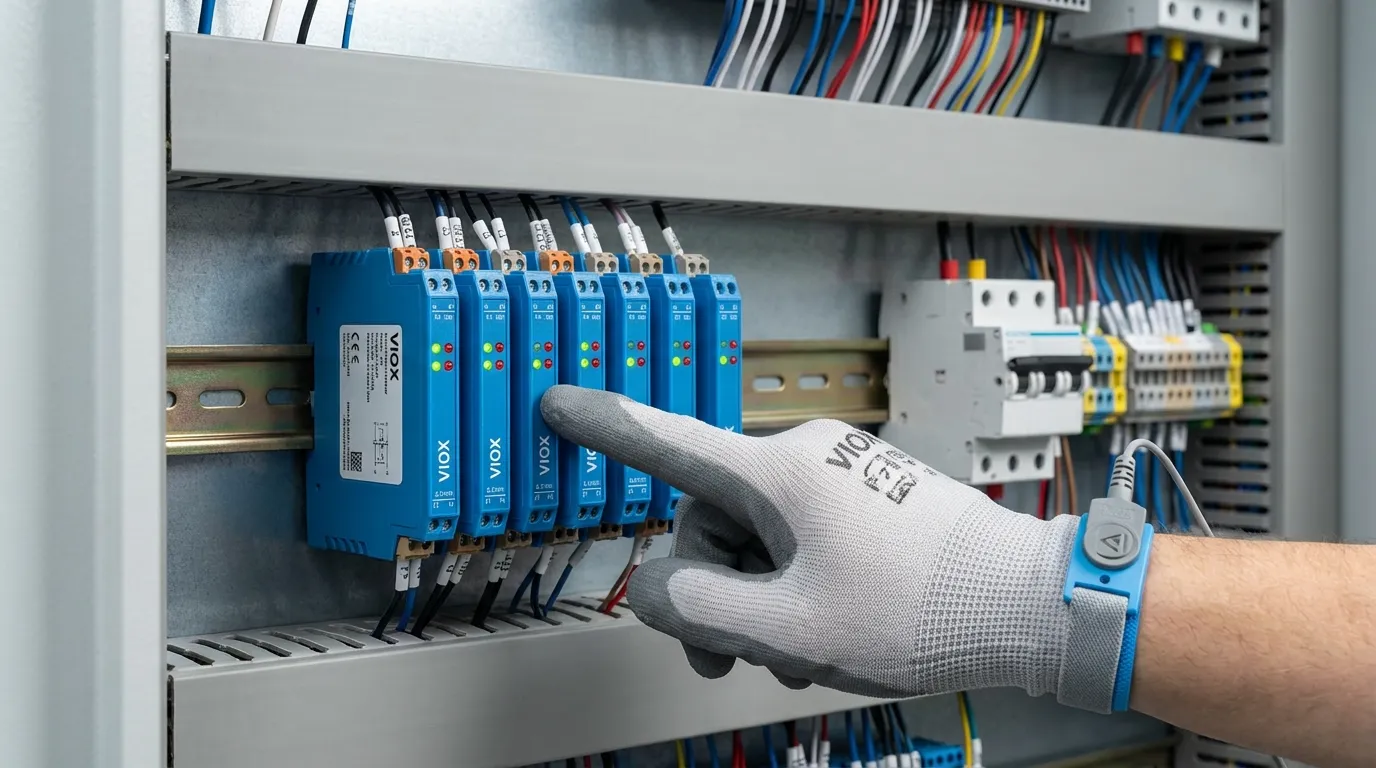
ایک انٹرفیس ریلے ماڈیول ایک پہلے سے جمع شدہ سوئچنگ یونٹ ہے جو خاص طور پر صنعتی آٹومیشن ایپلی کیشنز کے لیے ڈیزائن کیا گیا ہے۔ یہ ایک الیکٹرو مکینیکل ریلے کو مربوط پروٹیکشن سرکٹس، اسٹیٹس انڈیکیٹرز اور ایک معیاری ماؤنٹنگ سسٹم کے ساتھ جوڑتا ہے—عام طور پر DIN-ریل کے موافق۔ یہ ماڈیولز کم وولٹیج کنٹرول سگنلز (اکثر PLCs سے جو 24V DC پر کام کرتے ہیں) اور ہائی پاور فیلڈ ڈیوائسز جیسے موٹرز، سولینائڈز اور والوز کے درمیان اہم انٹرفیس کے طور پر کام کرتے ہیں۔.
انٹرفیس ریلے ماڈیولز کا فن تعمیر صنعتی کنٹرول میں ایک بنیادی چیلنج سے نمٹتا ہے: حساس کنٹرول الیکٹرانکس کو پاور سوئچنگ کے سخت برقی ماحول سے بچانا۔ جدید انٹرفیس ماڈیولز آپٹوکوپلر آئسولیشن کو شامل کرتے ہیں، جو کنٹرول ان پٹ اور ریلے کوائل کے درمیان ایک گالوانک رکاوٹ پیدا کرتا ہے۔ یہ آپٹیکل آئسولیشن وولٹیج اسپائکس، الیکٹرو میگنیٹک مداخلت اور گراؤنڈ لوپس کو PLC یا کنٹرول سسٹم میں واپس پھیلنے سے روکتا ہے۔.
ایک اسٹینڈرڈ پی سی بی ریلے کیا ہے؟
ایک اسٹینڈرڈ پی سی بی ریلے ایک مجرد الیکٹرو مکینیکل سوئچنگ جزو ہے جو براہ راست پرنٹ شدہ سرکٹ بورڈز پر سولڈرنگ کے لیے ڈیزائن کیا گیا ہے۔ ان ریلے میں بنیادی ریلے میکانزم—کوائل، آرمیچر اور کانٹیکٹس—بغیر مربوط پروٹیکشن سرکٹس یا ماؤنٹنگ انفراسٹرکچر کے شامل ہوتے ہیں۔ پی سی بی ریلے مختلف فٹ پرنٹس میں دستیاب ہیں، منی ایچر 10A اقسام سے جو صرف 15.8mm چوڑی ہیں، بڑی پاور ریلے جو 30A یا اس سے زیادہ کو ہینڈل کرتی ہیں۔.
پی سی بی ریلے کی سادگی انہیں ہائی والیوم مینوفیکچرنگ کے لیے پرکشش بناتی ہے جہاں فی یونٹ لاگت سب سے اہم ہے۔ تاہم، یہ سادگی تجارتی توازن کے ساتھ آتی ہے۔ سرکٹ ڈیزائنرز کو بیرونی اجزاء شامل کرنے چاہئیں جن میں کوائل سپریشن کے لیے فلائی بیک ڈائیوڈس، کرنٹ محدود کرنے والے ریزسٹرس، ایل ای ڈی انڈیکیٹرز اور اکثر ٹرانزسٹر یا MOSFET ڈرائیورز مائیکرو کنٹرولرز کے ساتھ انٹرفیس کرنے کے لیے۔ کل اجزاء کی تعداد اور پی سی بی کی جگہ کی ضرورت اکثر ابتدائی لاگت کے فائدے کو ختم کر دیتی ہے، خاص طور پر کم سے درمیانے درجے کی پروڈکشن والیوم میں۔.
اسٹینڈرڈ پی سی بی ریلے ان ایپلی کیشنز میں بہترین ہیں جہاں ریلے مستقل طور پر پروڈکٹ کے الیکٹرانکس میں مربوط ہے—جیسے HVAC کنٹرولرز، ایپلائینسز یا آٹوموٹو ماڈیولز—جہاں پروڈکٹ کی سروس لائف کے دوران فیلڈ ریپلیسمنٹ کی توقع نہیں کی جاتی ہے۔ ریلے مجموعی سرکٹ بورڈ اسمبلی کا حصہ بن جاتی ہے، جس کی جانچ اور توثیق ایک مکمل یونٹ کے طور پر کی جاتی ہے۔.
تفصیلی موازنہ: انٹرفیس ماڈیولز بمقابلہ پی سی بی ریلے
تنصیب اور انضمام
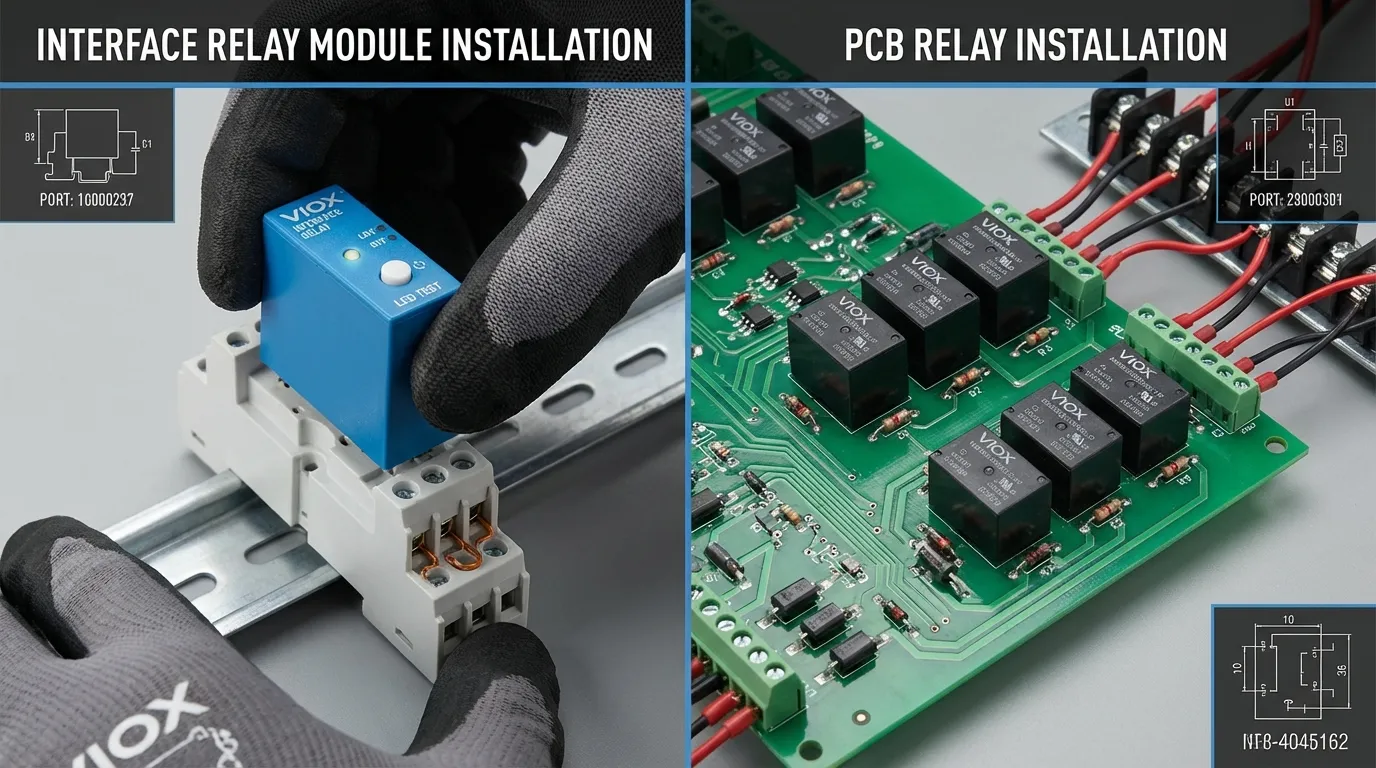
انٹرفیس ریلے ماڈیولز اپنے پلگ اینڈ پلے فن تعمیر کے ذریعے پینل اسمبلی میں انقلاب برپا کرتے ہیں۔ ریلے ایک پہلے سے وائرڈ ساکٹ بیس میں پلگ ہوتی ہے، جو مستقل طور پر DIN ریل پر نصب رہتی ہے۔ سوئچنگ عنصر کی وائرنگ انفراسٹرکچر سے یہ علیحدگی کا مطلب ہے کہ تکنیکی ماہرین بغیر ٹولز کے، ملحقہ سرکٹس میں خلل ڈالے بغیر اور وائرنگ کی غلطیوں کے خطرے کے بغیر ناکام ریلے کو تبدیل کر سکتے ہیں۔ مکمل ریلے سرکٹ کے لیے تنصیب کا وقت—ان پیکنگ سے لے کر آپریشنل ٹیسٹنگ تک—فی ریلے اوسطاً 3-5 منٹ ہے۔.
اسٹینڈرڈ پی سی بی ریلے ایک بنیادی طور پر مختلف انضمام کے نقطہ نظر کا مطالبہ کرتے ہیں۔ ریلے کو اس کے معاون اجزاء کے ساتھ ایک کسٹم ڈیزائن کردہ پی سی بی پر سولڈر کیا جانا چاہیے۔ اس پی سی بی کو پھر ماؤنٹنگ ہارڈ ویئر کی ضرورت ہوتی ہے، عام طور پر اسٹینڈ آف یا بریکٹ، تاکہ اسے کنٹرول پینل کے اندر محفوظ کیا جا سکے۔ وائر ٹرمینیشنز پی سی بی پر سکرو ٹرمینلز یا سولڈر پیڈز سے جڑتے ہیں۔ اگرچہ یہ نقطہ نظر خودکار اسمبلی کے ساتھ پروڈکشن ماحول میں اچھی طرح سے کام کرتا ہے، لیکن یہ فیلڈ انسٹالیشن اور دیکھ بھال کے لیے اہم چیلنجز پیدا کرتا ہے۔.
وائرنگ کا طریقہ کار کافی حد تک مختلف ہے۔ انٹرفیس ماڈیولز اسپرنگ کلیمپ یا سکرو ٹرمینلز استعمال کرتے ہیں جو صنعتی وائر گیجز (عام طور پر 0.5-2.5mm² / 20-14 AWG) کے لیے ڈیزائن کیے گئے ہیں، جو ٹھوس اور پھنسے ہوئے کنڈکٹرز دونوں کو قبول کرتے ہیں۔ پی سی بی ریلے کو یا تو براہ راست پی سی بی ٹریسز یا فلائنگ لیڈز کی ضرورت ہوتی ہے جو پیڈز پر سولڈر کیے جاتے ہیں—کوئی بھی نقطہ نظر آسان فیلڈ ترمیم یا ٹربل شوٹنگ کی سہولت فراہم نہیں کرتا ہے۔.
برقی تحفظ اور آئسولیشن
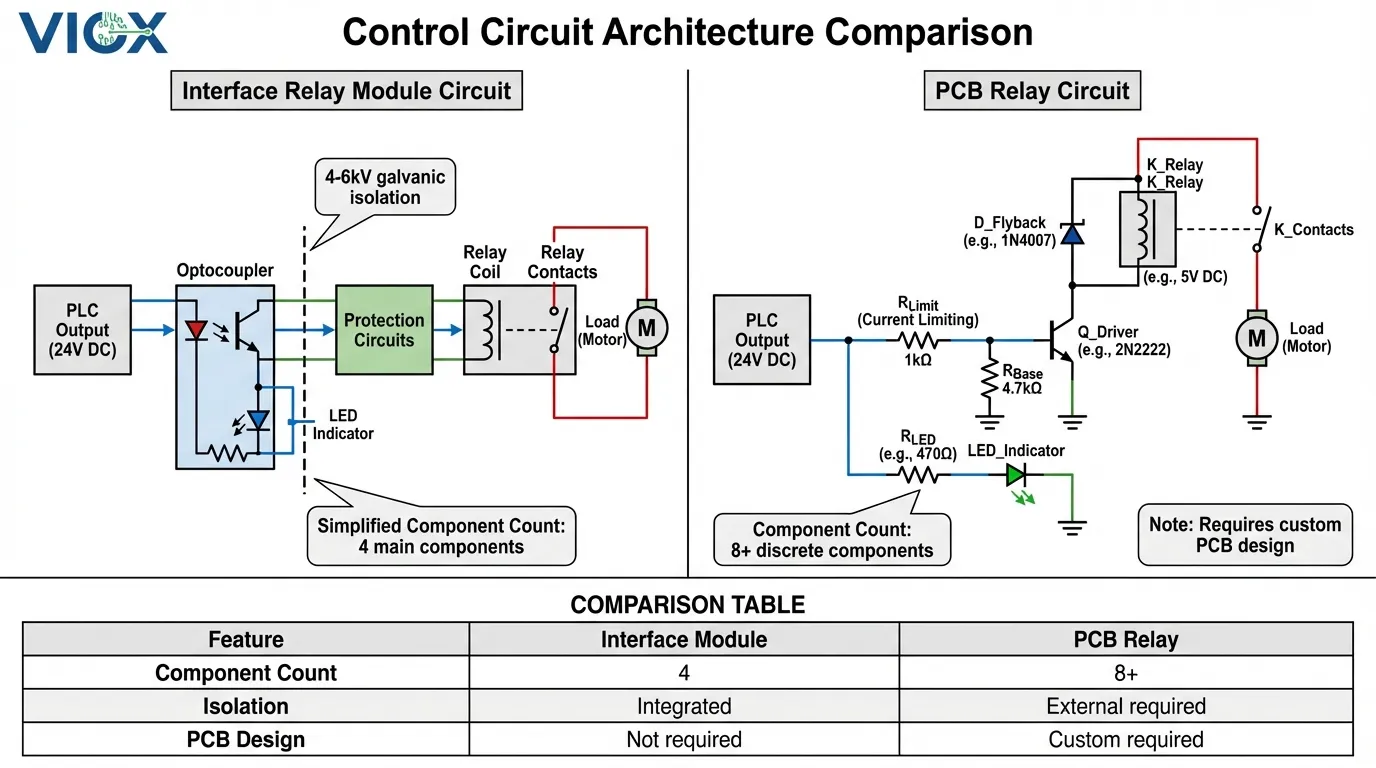
برقی آئسولیشن فن تعمیر شاید ان دو ریلے اقسام کے درمیان سب سے اہم فعال فرق کی نمائندگی کرتا ہے۔ انٹرفیس ریلے ماڈیولز عام طور پر کنٹرول ان پٹ پر آپٹوکوپلر آئسولیشن کو شامل کرتے ہیں، جو 4,000V اور 6,000V کے درمیان ریٹیڈ ایک گالوانک رکاوٹ پیدا کرتا ہے۔ یہ آپٹیکل آئسولیشن اس بات کو یقینی بناتا ہے کہ وولٹیج ٹرانزینٹس، گراؤنڈ پوٹینشل اختلافات، یا بوجھ کی طرف الیکٹرو میگنیٹک مداخلت کنٹرول سسٹم میں واپس نہیں پھیل سکتی۔.
آپٹوکوپلر سرکٹ برقی کنٹرول سگنل کو ایل ای ڈی کے ذریعے روشنی میں تبدیل کرکے کام کرتا ہے، جو پھر ریلے کوائل کو متحرک کرنے کے لیے الگ تھلگ سائیڈ پر ایک فوٹو ٹرانزسٹر کو چالو کرتا ہے۔ اس روشنی پر مبنی سگنل کی منتقلی کا مطلب ہے کہ PLC آؤٹ پٹ اور ریلے کوائل کے درمیان لفظی طور پر کوئی برقی کنکشن نہیں ہے—صرف ایک آپٹیکل راستہ ہے۔ یہ فن تعمیر مہنگے PLC آؤٹ پٹ کارڈز کی حفاظت کرتا ہے، جن کی قیمت عام طور پر فی ماڈیول 200 ڈالر سے 800 ڈالر ہوتی ہے، وولٹیج اسپائکس یا وائرنگ کی خرابیوں کی وجہ سے نقصان سے۔.
اسٹینڈرڈ پی سی بی ریلے صرف ریلے کوائل اور کانٹیکٹس کے درمیان موروثی آئسولیشن فراہم کرتے ہیں—عام طور پر IEC 61810-1 معیارات کے مطابق 4,000V پر ریٹیڈ۔ اگرچہ یہ کوائل سے رابطہ کی آئسولیشن بہت سی ایپلی کیشنز کے لیے کافی ہے، لیکن یہ ریلے کوائل چلانے والے کنٹرول سرکٹ کے لیے کوئی تحفظ فراہم نہیں کرتی ہے۔ کوائل ٹرمینلز پر کوئی بھی وولٹیج اسپائک براہ راست مائیکرو کنٹرولر یا PLC آؤٹ پٹ میں واپس پھیل سکتا ہے۔ سرکٹ ڈیزائنرز کو مساوی تحفظ حاصل کرنے کے لیے بیرونی تحفظ کے اجزاء—TVS ڈائیوڈس، آپٹوکوپلرز، یا آئسولیشن ایمپلیفائرز—شامل کرنے چاہئیں، جس سے لاگت اور پیچیدگی دونوں میں اضافہ ہوتا ہے۔.
عملی مضمرات صنعتی ماحول میں واضح ہو جاتے ہیں جن میں طویل کیبل رنز، انڈکٹیو بوجھ اور ممکنہ گراؤنڈ لوپس ہوتے ہیں۔ ایک موٹر اسٹارٹر سرکٹ جو 3 فیز کنٹیکٹر کو سوئچ کرتا ہے، مداخلت کے دوران 1,000V سے زیادہ وولٹیج ٹرانزینٹس پیدا کر سکتا ہے۔ مناسب آئسولیشن کے بغیر، یہ ٹرانزینٹس PLC آؤٹ پٹس کو نقصان پہنچا سکتے ہیں، کنٹرول سگنلز کو خراب کر سکتے ہیں، یا پریشان کن ٹرپس کا سبب بن سکتے ہیں۔ مربوط آپٹوکوپلر آئسولیشن والے انٹرفیس ماڈیولز ان حالات کو اپنے معیاری ڈیزائن کے حصے کے طور پر ہینڈل کرتے ہیں۔.
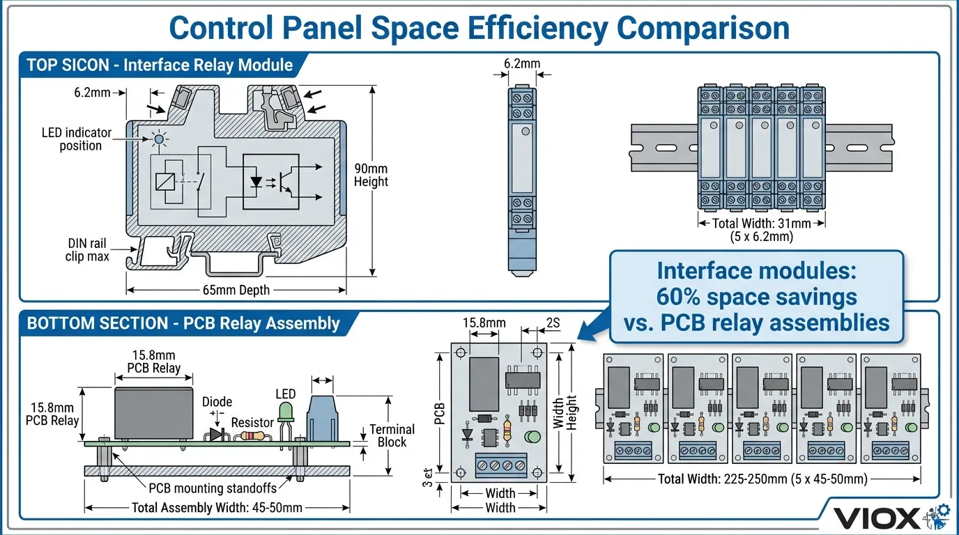
جگہ کی کارکردگی اور پینل کی کثافت
جدید صنعتی کنٹرول پینلز کو چھوٹے انکلوژرز میں زیادہ فعالیت پیک کرنے کے لیے مسلسل دباؤ کا سامنا ہے۔ انٹرفیس ریلے ماڈیولز الٹرا سلم ڈیزائن کے ذریعے اس چیلنج سے نمٹنے کے لیے تیار ہوئے ہیں۔ موجودہ نسل کے سلم ریلے ماڈیولز صرف 6.2mm چوڑے ہیں—ایک انچ کے ایک چوتھائی سے بھی کم—جبکہ 250V AC پر مکمل 6A سوئچنگ کی صلاحیت کو برقرار رکھتے ہیں۔ DIN ریل کا ایک معیاری 200mm سیکشن ان سلم ماڈیولز میں سے 32 کو ایڈجسٹ کر سکتا ہے، جو اسمارٹ فون سے چھوٹے فٹ پرنٹ میں 32 آزاد سوئچنگ سرکٹس فراہم کرتا ہے۔.
جگہ کی یہ کارکردگی خود ریلے سے آگے بڑھتی ہے۔ چونکہ انٹرفیس ماڈیولز پروٹیکشن سرکٹس، انڈیکیٹرز اور ٹرمینل کنکشن کو مربوط کرتے ہیں، اس لیے وہ علیحدہ پی سی بی اسمبلیوں، ماؤنٹنگ بریکٹس اور انٹر کنیکٹنگ وائرنگ کی ضرورت کو ختم کرتے ہیں جو پی سی بی ریلے انسٹالیشنز کے لیے ضروری ہیں۔ انٹرفیس ماڈیول حل کے ذریعے استعمال ہونے والا کل پینل والیوم عام طور پر مساوی پی سی بی ریلے کے نفاذ سے 40-60% کم ہوتا ہے جب تمام معاون اجزاء اور ماؤنٹنگ ہارڈ ویئر پر غور کیا جاتا ہے۔.
اسٹینڈرڈ پی سی بی ریلے، اگرچہ انفرادی اجزاء کے طور پر کمپیکٹ ہیں، لیکن کافی معاون انفراسٹرکچر کی ضرورت ہوتی ہے۔ ایک عام منی ایچر پی سی بی ریلے 15.8mm چوڑی ہے، لیکن مکمل پی سی بی اسمبلی بشمول ریلے، ساکٹ، پروٹیکشن ڈائیوڈس، ڈرائیور ٹرانزسٹر، ایل ای ڈی انڈیکیٹر اور ٹرمینل بلاکس پینل کی 40-60mm چوڑائی پر قابض ہے۔ ایک ہی پی سی بی پر متعدد ریلے سرکٹس کثافت کو بہتر بنا سکتے ہیں، لیکن لچک کی قیمت پر—اگر ایک ریلے ناکام ہو جاتی ہے، تو پورے بورڈ کو اکثر تبدیل کرنے کی ضرورت ہوتی ہے۔.
انٹرفیس ماڈیولز کے ذریعے استعمال کیا جانے والا DIN-ریل ماؤنٹنگ سسٹم پینل لے آؤٹ لچک میں اضافی فوائد فراہم کرتا ہے۔ ماڈیولز کو کسی بھی ترتیب میں ترتیب دیا جا سکتا ہے، آسانی سے منتقل کیا جا سکتا ہے، یا ماؤنٹنگ ڈھانچے کو دوبارہ ڈیزائن کیے بغیر توسیع کی جا سکتی ہے۔ پی سی بی اسمبلیوں کو پینل ڈیزائن کے دوران طے شدہ فکسڈ ماؤنٹنگ پوزیشنوں کی ضرورت ہوتی ہے، جس سے فیلڈ میں ترمیم مشکل ہو جاتی ہے۔.
دیکھ بھال اور سروس کی اہلیت
انٹرفیس ریلے ماڈیولز کا سروس کی اہلیت کا فائدہ غیر منصوبہ بند ڈاؤن ٹائم ایونٹس کے دوران سب سے زیادہ واضح ہو جاتا ہے۔ جب پروڈکشن ماحول میں ایک ریلے ناکام ہو جاتی ہے، تو ڈاؤن ٹائم کا ہر منٹ براہ راست کھوئے ہوئے ریونیو میں ترجمہ ہوتا ہے—اکثر خودکار مینوفیکچرنگ لائنوں کے لیے ہزاروں ڈالر فی گھنٹہ میں ماپا جاتا ہے۔ انٹرفیس ماڈیولز 60 سیکنڈ سے بھی کم وقت میں تبدیلی کو فعال کرتے ہیں: ناکام ریلے کو اس کے ساکٹ سے کھینچیں، ایک متبادل پلگ ان کریں، ایل ای ڈی انڈیکیٹرز کی تصدیق کریں اور آپریشن کو بحال کریں۔ کسی ٹولز کی ضرورت نہیں، وائرنگ میں کوئی تبدیلی نہیں، کنکشن کی غلطیوں کا کوئی خطرہ نہیں۔.
یہ پلگ اینڈ پلے مینٹیننس ماڈل احتیاطی دیکھ بھال کی حکمت عملیوں کی بھی حمایت کرتا ہے۔ دیکھ بھال کرنے والی ٹیمیں اسپیئر ریلے ماڈیولز کی ایک معمولی انوینٹری اسٹاک کر سکتی ہیں—عام طور پر نصب شدہ مقدار کا 10-20%—یہ جانتے ہوئے کہ یہ اسپیئرز متعدد پینل ڈیزائنز اور ایپلی کیشنز میں مطابقت رکھتے ہیں۔ ریلے ماڈیولز خود اکثر رنگ کوڈت ہوتے ہیں یا وولٹیج ریٹنگ کے لحاظ سے لیبل لگائے جاتے ہیں، جس سے کم تجربہ کار تکنیکی ماہرین کے لیے بھی بصری تصدیق آسان ہو جاتی ہے۔.
اسٹینڈرڈ پی سی بی ریلے کی دیکھ بھال اہم چیلنجز پیش کرتی ہے۔ ناکام پی سی بی ریلے کو تبدیل کرنے کے لیے پرانے جزو کو ڈی سولڈر کرنا اور ایک نیا سولڈر کرنا ضروری ہے—ایک ایسا کام جس کے لیے خصوصی مہارت، ٹولز اور وقت درکار ہوتا ہے۔ صنعتی ماحول میں، اس کا اکثر مطلب پورے پی سی بی اسمبلی کو پینل سے ہٹانا، اسے ورک بینچ یا مرمت کی سہولت تک پہنچانا، مرمت کرنا اور دوبارہ انسٹال کرنا ہوتا ہے۔ اگر متبادل پی سی بی فوری طور پر دستیاب نہیں ہیں تو کل ڈاؤن ٹائم گھنٹوں یا دنوں تک بڑھ سکتا ہے۔.
جانچ اور تصدیق کا عمل بھی کافی حد تک مختلف ہے۔ انٹرفیس ماڈیولز ایل ای ڈی انڈیکیٹرز کو شامل کرتے ہیں جو پاور اسٹیٹس اور ریلے اسٹیٹ دونوں کو ظاہر کرتے ہیں، جو ٹیسٹ آلات کے بغیر آپریشن کی بصری تصدیق کو فعال کرتے ہیں۔ بہت سے ماڈیولز میں دستی ٹیسٹ بٹن شامل ہوتے ہیں جو تکنیکی ماہرین کو کنٹرول سسٹم سے آزاد ریلے آپریشن کی تصدیق کرنے کی اجازت دیتے ہیں۔ پی سی بی ریلے سرکٹس کو مناسب آپریشن کی تصدیق کے لیے ملٹی میٹر ٹیسٹنگ یا آسکیلو اسکوپ تجزیہ کی ضرورت ہوتی ہے—زیادہ وقت طلب اور اعلیٰ مہارت کی سطح کی ضرورت ہوتی ہے۔.
لاگت کا تجزیہ: ابتدائی بمقابلہ ملکیت کی کل لاگت
انٹرفیس ماڈیولز اور پی سی بی ریلے کے درمیان لاگت کا موازنہ ایک کلاسک ابتدائی لاگت بمقابلہ ملکیت کی کل لاگت کا منظر نامہ ظاہر کرتا ہے۔ اسٹینڈرڈ پی سی بی ریلے کی قیمت اعتدال پسند مقدار میں 2-5 ڈالر فی یونٹ ہے، جبکہ انٹرفیس ریلے ماڈیولز کی قیمتیں تصریحات کے لحاظ سے 8-25 ڈالر تک ہوتی ہیں۔ یہ 3-5x قیمت کا فرق پی سی بی ریلے کو ابتدائی بجٹ میں زیادہ اقتصادی ظاہر کرتا ہے۔.
تاہم، جامع لاگت کے تجزیے میں تمام متعلقہ اجزاء اور مزدوری شامل ہونی چاہیے۔ ایک فعال پی سی بی ریلے سرکٹ کے لیے ضرورت ہے: ریلے (3 ڈالر)، ساکٹ (1.50 ڈالر)، فلائی بیک ڈائیوڈ (0.20 ڈالر)، ڈرائیور ٹرانزسٹر (0.30 ڈالر)، کرنٹ محدود کرنے والا ریزسٹر (0.05 ڈالر)، ایل ای ڈی انڈیکیٹر (0.15 ڈالر) اور ٹرمینل بلاکس (2.50 ڈالر)—صرف اجزاء میں تقریباً 7.70 ڈالر۔ کسٹم پی سی بی ڈیزائن (500-2,000 ڈالر فی ڈیزائن)، پی سی بی فیبریکیشن (1-3 ڈالر فی بورڈ)، اسمبلی لیبر (5-10 ڈالر فی ریلے سرکٹ) اور جانچ کا وقت شامل کریں، اور فی ریلے سرکٹ کی اصل لاگت 15-20 ڈالر تک پہنچ جاتی ہے۔.
انٹرفیس ریلے ماڈیولز 12-15 ڈالر فی یونٹ اچانک لاگت کے لحاظ سے مسابقتی ہو جاتے ہیں، خاص طور پر جب تنصیب کی مزدوری پر غور کیا جائے۔ پینل بنانے والوں نے پی سی بی ریلے اسمبلیوں کے مقابلے میں انٹرفیس ماڈیولز استعمال کرتے وقت اسمبلی کے وقت میں 40-50% کمی کی اطلاع دی ہے۔ 50 ریلے کنٹرول پینل کے لیے، یہ وقت کی بچت 20 لیبر گھنٹوں سے زیادہ ہو سکتی ہے—جو عام صنعتی لیبر ریٹس پر براہ راست لاگت کی بچت میں 600-1,200 ڈالر کی نمائندگی کرتی ہے۔.
دیکھ بھال کی لاگت کا فرق نظام کی زندگی کے دوران بڑھ جاتا ہے۔ ایک ناکام انٹرفیس ماڈیول کی قیمت 12-15 ڈالر اور تکنیکی ماہر کا 5 منٹ کا وقت (8-10 ڈالر) ہے جس کی کل مرمت کی لاگت 25 ڈالر سے کم ہے۔ ایک ناکام پی سی بی ریلے سرکٹ کے لیے اکثر پورے پی سی بی اسمبلی (50-150 ڈالر) کے علاوہ ہنر مند تکنیکی ماہر کے 1-2 گھنٹے (100-200 ڈالر) کی ضرورت ہوتی ہے، جس کی کل قیمت 150-350 ڈالر فی ناکامی ہوتی ہے۔ عام صنعتی ریلے کی ناکامی کی شرح (سالانہ 0.5-1%) کے ساتھ 10 سالہ سروس لائف میں، انٹرفیس ماڈیولز کا دیکھ بھال کی لاگت کا فائدہ فی پینل 500-1,000 ڈالر سے زیادہ ہو سکتا ہے۔.
تکنیکی تصریحات کا موازنہ ٹیبل
| تفصیلات | انٹرفیس ریلے ماڈیول | اسٹینڈرڈ پی سی بی ریلے |
|---|---|---|
| رابطہ کی درجہ بندی | 6A @ 250V AC (عام سلم ماڈیولز) 10-16A @ 250V AC (معیاری ماڈیولز) |
5-10A @ 250V AC (منی ایچر) 10-30A @ 250V AC (پاور ریلے) |
| وولٹیج کو کنٹرول کریں۔ | 24V DC، 24V AC، 120V AC، 230V AC (پلگ ان کوائل کے اختیارات) |
ڈیزائن کے مطابق کسٹم (عام طور پر 5V، 12V، 24V DC) |
| برقی تنہائی | 4-6kV (آپٹوکوپلر ان پٹ آئسولیشن) + 4kV (کوائل سے رابطہ) |
4kV (صرف IEC 61810-1 کے مطابق کوائل سے رابطہ) |
| رسپانس ٹائم | 8-12ms (عام الیکٹرو مکینیکل) | 5-10ms (عام الیکٹرو مکینیکل) |
| مکینیکل لائف | 10-20 ملین آپریشنز | 10 ملین آپریشنز (عام) |
| برقی زندگی | 100,000 آپریشنز @ ریٹیڈ لوڈ | 100,000 آپریشنز @ ریٹیڈ لوڈ |
| آپریٹنگ درجہ حرارت | -40°C سے +70°C (صنعتی گریڈ) | -40°C سے +85°C (ماڈل کے لحاظ سے مختلف) |
| ماؤنٹنگ کا طریقہ | ڈی آئی این ریل (35 ملی میٹر معیاری) پلگ ان ساکٹ |
پی سی بی سولڈرنگ (تھرو ہول یا ایس ایم ڈی) |
| حیثیت کا اشارہ | انٹیگریٹڈ ایل ای ڈی (پاور + ریلے اسٹیٹ) | بیرونی ایل ای ڈی سرکٹ درکار ہے |
| تحفظ کی خصوصیات | آپٹوکوپلر آئسولیشن کوائل سپریشن اضافے سے تحفظ |
بیرونی تحفظ سرکٹس درکار ہیں |
| تبدیلی کا وقت | <60 سیکنڈ (پلگ ان) | 15-30 منٹ (ڈیسولڈرنگ/سولڈرنگ) |
| فی یونٹ عام لاگت | $8-$25 | $2-$5 (صرف ریلے) $7-$10 (اجزاء کے ساتھ) |
| معیارات کی تعمیل | آئی ای سی 61810-1، یو ایل 508، سی ای | آئی ای سی 61810-1، یو ایل 508 (صرف ریلے) |
| کمپن مزاحمت | 10 گرام @ 10-55 ہرٹز (ڈی آئی این ریل پر نصب) | پی سی بی ماؤنٹنگ کے طریقہ کار پر منحصر ہے |
| ٹرمینل کی قسم | اسپرنگ-کلیمپ یا سکرو (0.5-2.5 ملی میٹر² تار) |
پی سی بی پیڈز یا سولڈر ٹرمینلز |
| فی سرکٹ چوڑائی | 6.2-12 ملی میٹر (انتہائی سلم ڈیزائن) | 15-20 ملی میٹر (صرف ریلے) 40-60 ملی میٹر (مکمل سرکٹ) |
ایپلیکیشن کے لحاظ سے انتخاب کے معیار
انٹرفیس ریلے ماڈیولز کب منتخب کریں
انٹرفیس ریلے ماڈیولز ان ایپلی کیشنز کے لیے بہترین انتخاب کی نمائندگی کرتے ہیں جو قابل اعتمادی، دیکھ بھال، اور طویل مدتی آپریشنل کارکردگی کو ترجیح دیتے ہیں۔ صنعتی آٹومیشن سسٹم، خاص طور پر وہ جو پی ایل سی کنٹرول میں شامل ہیں، ریلے ماڈیولز کے فراہم کردہ انٹیگریٹڈ تحفظ اور معیاری انٹرفیس سے بہت زیادہ فائدہ اٹھاتے ہیں۔ مینوفیکچرنگ کی سہولیات جہاں ڈاؤن ٹائم کی لاگت $1,000 فی گھنٹہ سے زیادہ ہے وہ پی سی بی ریلے کی ناکامیوں سے وابستہ توسیعی مرمت کے اوقات برداشت نہیں کر سکتیں۔.
بلڈنگ آٹومیشن سسٹم—ایچ وی اے سی کنٹرولز، لائٹنگ مینجمنٹ، اور ایکسیس کنٹرول—انٹرفیس ماڈیولز کی لچک اور سروس ایبلٹی سے فائدہ اٹھاتے ہیں۔ ان سسٹمز کو اکثر ابتدائی تنصیب کے سالوں بعد ترمیم یا توسیع کی ضرورت ہوتی ہے۔ انٹرفیس ماڈیولز کی پلگ اینڈ پلے نوعیت سہولت مینیجرز کو خصوصی الیکٹرانکس کی مہارت یا وسیع ڈاؤن ٹائم کے بغیر کنٹرول لاجک کو دوبارہ ترتیب دینے کی اجازت دیتی ہے۔.
پانی کی صفائی، کیمیکل پروسیسنگ، اور فوڈ پروڈکشن میں پروسیس کنٹرول ایپلی کیشنز کو ماحولیاتی مضبوطی اور برقی تنہائی کی ضرورت ہوتی ہے جو انٹرفیس ماڈیولز فراہم کرتے ہیں۔ ان صنعتوں کو درجہ حرارت کی انتہا، نمی، کمپن، اور برقی شور سمیت سخت حالات کا سامنا ہے۔ آئی ای سی 61810-1 صنعتی تصریحات پر پورا اترنے والے انٹرفیس ماڈیولز ان مشکل ماحول میں قابل اعتماد آپریشن کو یقینی بناتے ہیں۔.
کنٹرول پینل مینوفیکچررز اور سسٹم انٹیگریٹرز انٹرفیس ماڈیولز کو ان کے معیاری کاری کے فوائد کے لیے ترجیح دیتے ہیں۔ ایک پینل بنانے والا ایک معیاری ساکٹ لے آؤٹ ڈیزائن کر سکتا ہے، پھر ہر ایپلیکیشن کے لیے مناسب ریلے ماڈیولز کو منتخب کر کے ریلے کوائل وولٹیجز اور کنٹیکٹ انتظامات کو ترتیب دے سکتا ہے۔ یہ ماڈیولر نقطہ نظر ڈیزائن کے وقت کو کم کرتا ہے، انوینٹری مینجمنٹ کو آسان بناتا ہے، اور پیداوار کو تیز کرتا ہے۔.
معیاری پی سی بی ریلے کب منتخب کریں
معیاری پی سی بی ریلے ہائی والیوم پروڈکشن ماحول میں بہترین کارکردگی کا مظاہرہ کرتے ہیں جہاں ریلے ایک بڑے الیکٹرانک اسمبلی کا مستقل جزو بن جاتا ہے۔ صارفین کے آلات، ایچ وی اے سی کا سامان، اور آٹوموٹو الیکٹرانکس عام طور پر پی سی بی ریلے کو اپنے کنٹرول بورڈز میں ضم کرتے ہیں، جہاں ریلے کو پروڈکٹ کی متوقع سروس لائف کے دوران فیلڈ ریپلیسمنٹ کی ضرورت نہیں ہوگی۔.
مستحکم، اچھی طرح سے متعین ضروریات کے ساتھ لاگت سے حساس ایپلی کیشنز پی سی بی ریلے کے نفاذ سے فائدہ اٹھاتی ہیں۔ ایک بار جب سرکٹ ڈیزائن کو حتمی شکل دے دی جاتی ہے اور اس کی توثیق ہو جاتی ہے، تو پی سی بی ریلے سالانہ 1,000 یونٹس سے زیادہ کی پیداوار میں فی یونٹ کم لاگت پیش کرتے ہیں۔ بڑے پیمانے پر پیداوار میں پی سی بی ڈیزائن اور سیٹ اپ لاگت کی تخفیف اس نقطہ نظر کو اقتصادی طور پر پرکشش بناتی ہے۔.
کمپیکٹ الیکٹرانک آلات جہاں جگہ کا ہر ملی میٹر اہمیت رکھتا ہے وہ پی سی بی ریلے کو ان کے معاون جزو کی ضروریات کے باوجود ترجیح دے سکتے ہیں۔ جدید منی ایچر پی سی بی ریلے جو صرف 10-15 ملی میٹر کی پیمائش کرتے ہیں وہ ہینڈ ہیلڈ ڈیوائسز، پورٹیبل آلات، یا جگہ کی تنگی والی تنصیبات میں فٹ ہو سکتے ہیں جہاں ڈی آئی این ریل ماؤنٹنگ ممکن نہیں ہے۔.
کم سوئچنگ فریکوئنسی اور کم سے کم دیکھ بھال کی ضروریات والی ایپلی کیشنز کامیابی سے پی سی بی ریلے استعمال کر سکتی ہیں۔ ایک ریلے جو دن میں ایک بار یا اس سے کم سوئچ کرتا ہے، ایک صاف ماحول میں، متوقع سروس لائف 5 سال سے کم کے ساتھ، انٹرفیس ماڈیولز کی زیادہ ابتدائی لاگت کو جائز قرار نہیں دے سکتا ہے۔.
ہائبرڈ اپروچز اور خصوصی تحفظات
کچھ ایپلی کیشنز دونوں ریلے اقسام کو یکجا کرنے والے ہائبرڈ اپروچز سے فائدہ اٹھاتی ہیں۔ بڑے کنٹرول پینلز اکثر سوئچ کیے جانے والے یا اہم سرکٹس کے لیے انٹرفیس ماڈیولز استعمال کر سکتے ہیں جن کے لیے آسان دیکھ بھال کی ضرورت ہوتی ہے، جبکہ معاون افعال جیسے انڈیکیٹر لائٹس یا شاذ و نادر ہی چلنے والے انٹر لاکس کے لیے پی سی بی ریلے استعمال کرتے ہیں۔ یہ حکمت عملی لاگت اور فعالیت دونوں کو بہتر بناتی ہے۔.
حفاظتی لحاظ سے اہم ایپلی کیشنز کو ریلے کی قسم سے قطع نظر خصوصی غور و فکر کی ضرورت ہوتی ہے۔ جبری گائیڈڈ کنٹیکٹس والے حفاظتی ریلے—جہاں میکانکی ربط اس بات کو یقینی بناتا ہے کہ عام طور پر کھلے اور عام طور پر بند کنٹیکٹس بیک وقت بند نہیں ہو سکتے—انٹرفیس ماڈیول اور پی سی بی دونوں فارمیٹس میں دستیاب ہیں۔ یہ ریلے حفاظتی متعلقہ کنٹرول سسٹمز کے لیے آئی ای سی 61810-3 (EN 50205) معیارات کی تعمیل کرتے ہیں اور ایمرجنسی اسٹاپ سرکٹس، حفاظتی انٹر لاکس، اور مشین گارڈنگ ایپلی کیشنز کے لیے ضروری ہیں۔.
ہائی فریکوئنسی سوئچنگ ایپلی کیشنز جو 10 آپریشنز فی منٹ سے زیادہ ہیں وہ الیکٹرو مکینیکل ریلے کے بجائے سالڈ اسٹیٹ ریلے (ایس ایس آر) ٹیکنالوجی کی ضمانت دے سکتی ہیں۔ ایس ایس آر مکمل طور پر کنٹیکٹ پہننے کو ختم کرتے ہیں، جو کہ بنیادی طور پر لامحدود میکانکی زندگی پیش کرتے ہیں۔ تاہم، ایس ایس آر مختلف تحفظات متعارف کراتے ہیں جن میں حرارت کی کھپت، رساو کرنٹ، اور فی سوئچنگ پوائنٹ زیادہ لاگت شامل ہے۔.
معیارات کی تعمیل اور سرٹیفیکیشن
آئی ای سی 61810-1: فاؤنڈیشن اسٹینڈرڈ
آئی ای سی 61810-1 الیکٹرو مکینیکل ایلیمنٹری ریلے کے لیے بنیادی حفاظت اور کارکردگی کی ضروریات کو قائم کرتا ہے۔ یہ بین الاقوامی معیار کنٹیکٹ ریٹنگز، انسولیشن ریزسٹنس، ڈائی الیکٹرک طاقت، درجہ حرارت میں اضافے، اور میکانکی برداشت کے لیے ٹیسٹ کے طریقہ کار کی وضاحت کرتا ہے۔ صنعتی ایپلی کیشنز کے لیے موزوں ہونے کے لیے انٹرفیس ریلے ماڈیولز اور معیاری پی سی بی ریلے دونوں کو آئی ای سی 61810-1 کی تعمیل کرنی چاہیے۔.
معیار یہ بتاتا ہے کہ ریلے کو کوائل اور کنٹیکٹس کے درمیان ایک منٹ کے لیے 4,000V AC کے ڈائی الیکٹرک ٹیسٹ وولٹیج کو بغیر خرابی کے برداشت کرنا چاہیے۔ انسولیشن ریزسٹنس 500V DC پر 100MΩ سے زیادہ ہونا چاہیے۔ کنٹیکٹ ریزسٹنس مخصوص اقدار سے زیادہ نہیں ہونا چاہیے (عام طور پر پاور کنٹیکٹس کے لیے 100mΩ) تاکہ ضرورت سے زیادہ حرارت اور وولٹیج ڈراپ کو روکا جا سکے۔ ریٹیڈ لوڈ کے تحت درجہ حرارت میں اضافہ ان حدود سے زیادہ نہیں ہونا چاہیے جو انسولیشن مواد کو خراب کر دے یا ریلے کی زندگی کو کم کر دے۔.
انٹرفیس ریلے ماڈیولز اکثر ان کم از کم ضروریات سے تجاوز کر جاتے ہیں، خاص طور پر برقی تنہائی میں۔ کنٹرول ان پٹ پر آپٹوکوپلر آئسولیشن ریلے کی موروثی کوائل ٹو کنٹیکٹ آئسولیشن سے آگے ایک اضافی آئسولیشن رکاوٹ فراہم کرتا ہے، جو دفاع میں گہرائی کی تحفظ کی حکمت عملی بناتا ہے۔.
یو ایل 508 اور شمالی امریکہ کی ضروریات
یو ایل 508، صنعتی کنٹرول آلات کے لیے معیار، شمالی امریکہ کی مارکیٹوں میں ریلے ایپلی کیشنز کو کنٹرول کرتا ہے۔ یہ معیار بین الاقوامی آئی ای سی کی ضروریات کے ساتھ ہم آہنگ ہونے کے لیے تیار ہوا ہے، ہم آہنگ آئی ای سی/یو ایل 61810-1 معیار اب پچھلی یو ایل 508 ریلے تصریحات کی جگہ لے رہا ہے۔ یہ ہم آہنگی ریلے مینوفیکچررز کے لیے عالمی مارکیٹ تک رسائی کو آسان بناتی ہے اور کنٹرول پینل بنانے والوں کے لیے سرٹیفیکیشن کی پیچیدگی کو کم کرتی ہے۔.
یو ایل سرٹیفیکیشن کے لیے نہ صرف ریلے خود بلکہ کنٹرول پینل کے اندر اس کی ایپلیکیشن کو بھی حفاظتی ضروریات کو پورا کرنا ضروری ہے۔ مناسب تار سائزنگ، اوور کرنٹ پروٹیکشن، اور اسپیسنگ کی ضروریات سبھی یو ایل پینل سرٹیفیکیشن میں شامل ہیں۔ یو ایل سے تسلیم شدہ اجزاء اور معیاری ماؤنٹنگ طریقوں والے انٹرفیس ریلے ماڈیولز پینل سرٹیفیکیشن کے عمل کو آسان بناتے ہیں۔.
سی ای مارکنگ اور یورپی تعمیل
سی ای مارکنگ یورپی یونین کی حفاظت، صحت، اور ماحولیاتی تحفظ کے معیارات کے ساتھ مطابقت کی نشاندہی کرتی ہے۔ ریلے اور کنٹرول پینلز کے لیے، اس میں کم وولٹیج ڈائریکٹیو (ایل وی ڈی) اور الیکٹرو میگنیٹک کمپیٹیبلٹی (ای ایم سی) ڈائریکٹیو شامل ہیں۔ انٹیگریٹڈ ای ایم سی پروٹیکشن فیچرز—آپٹوکوپلر آئسولیشن، کوائل سپریشن، اور شیلڈڈ ہاؤسنگز—والے انٹرفیس ریلے ماڈیولز پینل بنانے والوں کو کسٹم ای ایم سی تخفیف کی ضرورت والی مجرد پی سی بی ریلے اسمبلیوں کے مقابلے میں سی ای تعمیل کو زیادہ آسانی سے حاصل کرنے میں مدد کرتے ہیں۔.
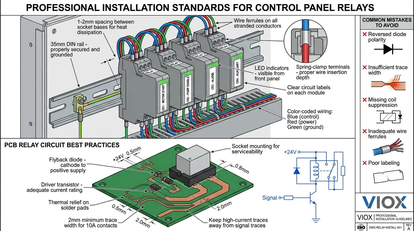
تنصیب کے بہترین طریقے
انٹرفیس ریلے ماڈیول کی تنصیب
انٹرفیس ریلے ماڈیولز کی مناسب تنصیب ڈی آئی این ریل کی تیاری سے شروع ہوتی ہے۔ اس بات کو یقینی بنائیں کہ ریل صاف ہے، پینل بیک پلیٹ پر مناسب طریقے سے محفوظ ہے، اور اگر کنڈکٹیو ریل استعمال کر رہے ہیں تو گراؤنڈ ہے۔ ساکٹ بیسز کو پہلے ماؤنٹ کریں، مستقل اسپیسنگ اور اورینٹیشن کو برقرار رکھیں۔ زیادہ تر مینوفیکچررز مناسب حرارت کی کھپت اور تار روٹنگ کلیئرنس کے لیے ملحقہ ساکٹس کے درمیان 1-2 ملی میٹر اسپیسنگ کی سفارش کرتے ہیں۔.
ریلے ماڈیولز انسٹال کرنے سے پہلے ساکٹ بیسز کو مکمل طور پر وائر کریں۔ پھنسے ہوئے کنڈکٹرز پر تار فیرولز استعمال کریں تاکہ اسٹرینڈ ٹوٹنے سے بچا جا سکے اور قابل اعتماد اسپرنگ-کلیمپ ٹرمینل کنکشن کو یقینی بنایا جا سکے۔ ڈی سی کوائل کنکشن پر پولرٹی کا مشاہدہ کریں—ریورس پولرٹی ریلے کو نقصان نہیں پہنچائے گی لیکن یہ کام نہیں کرے گی۔ اے سی کوائلز کے لیے، پولرٹی کوئی معنی نہیں رکھتی، لیکن مستقل وائرنگ کلر کوڈز کو برقرار رکھنے سے خرابیوں کا سراغ لگانے میں مدد ملتی ہے۔.
ہر ریلے پوزیشن کو واضح طور پر لیبل کریں، سرکٹ فنکشن، لوڈ کی تفصیل، اور کسی بھی خاص آپریٹنگ حالات کی نشاندہی کریں۔ بہت سے انٹرفیس ماڈیولز میں خاص طور پر اس مقصد کے لیے سامنے والے حصے پر لیبل ایریاز شامل ہوتے ہیں۔ جامع لیبلنگ خرابیوں کا سراغ لگانے کے وقت کو کم کرتی ہے اور دیکھ بھال کے دوران وائرنگ کی غلطیوں کو روکتی ہے۔.
مکمل پینل کو انرجائز کرنے سے پہلے ہر ریلے سرکٹ کی انفرادی طور پر جانچ کریں۔ درست کنٹرول وولٹیج کی تصدیق کریں، مناسب آپریشن کے لیے ایل ای ڈی اشارے چیک کریں، اور ملٹی میٹر سے کنٹیکٹ سوئچنگ کی تصدیق کریں۔ یہ منظم نقطہ نظر وائرنگ کی غلطیوں یا ناقص اجزاء کی نشاندہی کرتا ہے اس سے پہلے کہ وہ سسٹم کی سطح کے مسائل کا سبب بنیں۔.
پی سی بی ریلے سرکٹ ڈیزائن گائیڈ لائنز
پی سی بی ریلے سرکٹ ڈیزائن کے لیے کئی اہم عوامل پر احتیاط سے توجہ دینے کی ضرورت ہے۔ فلائی بیک ڈائیوڈس (1N4007 یا مساوی) کو براہ راست ریلے کوائلز کے پار مثبت سپلائی کی طرف کیتھوڈ کے ساتھ رکھیں۔ یہ ڈائیوڈ انڈکٹیو وولٹیج اسپائک کو کلیمپ کرتا ہے جو کوائل کے ڈی انرجائز ہونے پر پیدا ہوتا ہے، ڈرائیور ٹرانزسٹرز اور مائیکرو کنٹرولرز کی حفاظت کرتا ہے۔ اس تحفظ کے بغیر، کوائل وولٹیج اسپائکس 100V سے تجاوز کر سکتے ہیں، سیمیکمڈکٹر اجزاء کو تباہ کر سکتے ہیں۔.
ڈرائیور ٹرانزسٹر کا انتخاب ریلے کوائل کرنٹ اور کنٹرول سگنل کی خصوصیات پر منحصر ہے۔ 24mA ڈرا کرنے والے 1,000Ω کوائلز والے 24V DC ریلے کے لیے، 2N2222 جیسا ایک عام مقصد والا NPN ٹرانزسٹر کافی ہے۔ زیادہ کرنٹ والے کوائلز کو پاور ٹرانزسٹرز یا MOSFETs کی ضرورت ہوتی ہے۔ بیس کرنٹ کی ضروریات کا حساب لگائیں جو مناسب سیچوریشن کو یقینی بناتی ہیں—عام طور پر کلیکٹر کرنٹ کے لیے درکار بیس کرنٹ کا 10 گنا قابل اعتماد سوئچنگ کو یقینی بناتا ہے۔.
پی سی بی ٹریس کی چوڑائی کو ضرورت سے زیادہ وولٹیج ڈراپ یا حرارت کے بغیر ریلے کنٹیکٹ کرنٹ کو ایڈجسٹ کرنا چاہیے۔ 10A کنٹیکٹس کے لیے، 1oz تانبے پر کم از کم 2 ملی میٹر (80 مل) ٹریس کی چوڑائی استعمال کریں۔ بہتر وشوسنییتا اور کم درجہ حرارت میں اضافے کے لیے 3-4 ملی میٹر تک بڑھانے پر غور کریں۔ برقی مقناطیسی مداخلت کو کم کرنے کے لیے حساس سگنل ٹریسز سے دور ہائی کرنٹ ٹریسز کو روٹ کریں۔.
ماؤنٹنگ تحفظات میں میکانکی تناؤ سے نجات شامل ہے۔ ریلے کنٹیکٹس سوئچنگ کے دوران اہم میکانکی قوت پیدا کرتے ہیں—کئی نیوٹن تک—جو وقت کے ساتھ ساتھ سولڈر جوڑوں کو توڑ سکتی ہے۔ ریلے پن فی ایک سے زیادہ سولڈر پیڈ استعمال کریں، یا بہتر سروس ایبلٹی کے لیے براہ راست سولڈرنگ کے بجائے پی سی بی پر ساکٹ ماؤنٹنگ ریلے پر غور کریں۔.
عام مسائل کا ازالہ کرنا
انٹرفیس ریلے ماڈیول کے مسائل
ریلے انرجائز نہیں ہوگا: ماڈیول ان پٹ ٹرمینلز پر کنٹرول وولٹیج چیک کریں۔ انٹرفیس ماڈیولز کو قابل اعتماد طریقے سے کام کرنے کے لیے عام طور پر برائے نام وولٹیج کا 70-80% درکار ہوتا ہے۔ ایل ای ڈی اشارے کی تصدیق کریں—اگر پاور ایل ای ڈی روشن ہو جائے لیکن ریلے سوئچ نہ کرے، تو ریلے ماڈیول خود خراب ہو سکتا ہے۔ ساکٹ میں ریلے ڈالنے سے روکنے والی میکانکی رکاوٹوں کی جانچ کریں۔.
وقفے وقفے سے آپریشن: ڈھیلے ٹرمینل کنکشن سب سے عام وجہ ہیں۔ اسپرنگ-کلیمپ ٹرمینلز کو تار کی مناسب گہرائی میں ڈالنے کی ضرورت ہوتی ہے—عام طور پر 10-12 ملی میٹر۔ ناکافی اندراج ہائی ریزسٹنس کنکشن بناتا ہے جو لوڈ کے تحت گرم ہوتے ہیں اور بالآخر ناکام ہو جاتے ہیں۔ آکسائڈائزڈ یا خراب تار کے سروں کی جانچ کریں۔ وائبریشن بھی وقت کے ساتھ ساتھ سکرو ٹرمینلز کو ڈھیلا کر سکتی ہے۔ مناسب ٹارک کی تصریح کی تصدیق کریں (عام طور پر 0.5-0.8 Nm)۔.
کانٹیکٹ ویلڈنگ یا جلنا: اس بات کی نشاندہی کرتا ہے کہ ریلے اپنی ریٹنگ سے زیادہ لوڈ کو سوئچ کر رہا ہے یا مناسب سپریشن کے بغیر انتہائی انڈکٹیو لوڈ کو سوئچ کر رہا ہے۔ ریلے کی تصریحات کے خلاف اصل لوڈ کرنٹ کی تصدیق کریں۔ انڈکٹیو لوڈز (موٹرز، سولینائڈز، ٹرانسفارمرز) کو ڈیریٹنگ کی ضرورت ہوتی ہے—عام طور پر ریزسٹیو لوڈ ریٹنگ کا 50%۔ سوئچنگ ٹرانزینٹس کو دبانے کے لیے انڈکٹیو لوڈز کے پار RC سنبرز یا ویریسٹرز شامل کریں۔.
قبل از وقت ناکامی: ماحولیاتی عوامل اکثر ابتدائی ریلے کی ناکامی میں معاون ہوتے ہیں۔ ضرورت سے زیادہ محیطی درجہ حرارت (>60°C) ریلے کی زندگی کو ڈرامائی طور پر کم کر دیتا ہے۔ مناسب پینل وینٹیلیشن کو یقینی بنائیں اور متعدد ریلے کو قریب سے لگاتے وقت حرارت کی کھپت پر غور کریں۔ دھول، نمی یا کیمیائی بخارات سے آلودگی موصلیت کو کم کر سکتی ہے اور کانٹیکٹس کو خراب کر سکتی ہے۔.
پی سی بی ریلے سرکٹ کے مسائل
کوائل انرجائز نہیں ہوگا: ڈرائیور ٹرانزسٹر آپریشن کی تصدیق کریں۔ ٹرانزسٹر کلیکٹر پر وولٹیج کی پیمائش کریں—بند ہونے پر سپلائی وولٹیج کے قریب ہونا چاہیے، آن ہونے پر صفر کے قریب ہونا چاہیے۔ بیس کرنٹ چیک کریں—ناکافی بیس ڈرائیو ٹرانزسٹر سیچوریشن کو روکتی ہے۔ فلائی بیک ڈائیوڈ کی تصدیق کریں کہ وہ شارٹ نہیں ہے، جو کوائل وولٹیج کو ~0.7V تک کلیمپ کر دے گا۔ کوائل ریزسٹنس کی پیمائش کریں۔ کھلی کوائلز ریلے کی ناکامی کی نشاندہی کرتی ہیں۔.
ڈرائیور ٹرانزسٹر کی ناکامی: عام طور پر غائب یا ریورس فلائی بیک ڈائیوڈ کی وجہ سے ہوتا ہے۔ کوائل ڈی-انرجائزیشن سے انڈکٹیو سپائک ٹرانزسٹر بریک ڈاؤن وولٹیج سے تجاوز کر سکتا ہے، جس سے جنکشن تباہ ہو جاتا ہے۔ ہمیشہ درست پولرٹی کے ساتھ ڈائیوڈ انسٹال کریں۔ شور والے ماحول میں تیز تر ردعمل کے لیے Schottky ڈائیوڈ یا بہتر تحفظ کے لیے TVS ڈائیوڈ استعمال کرنے پر غور کریں۔.
کانٹیکٹ آرکنگ یا پٹنگ: ریلے کی صلاحیت سے زیادہ لوڈ کو سوئچ کرنے یا ناکافی آرک سپریشن کے نتیجے میں ہوتا ہے۔ AC لوڈز کو DC لوڈز کے مقابلے میں مختلف سپریشن کی ضرورت ہوتی ہے۔ AC کے لیے، RC سنبرز استعمال کریں (کانٹیکٹس کے پار 0.1µF + 100Ω)۔ DC کے لیے، انڈکٹیو لوڈز کے پار فری وہیلنگ ڈائیوڈ استعمال کریں۔ زیادہ کانٹیکٹ ریٹنگ والے ریلے میں اپ گریڈ کرنے یا 10A سے زیادہ لوڈ کے لیے کانٹیکٹرز پر سوئچ کرنے پر غور کریں۔.
EMI/RFI مسائل: ریلے سوئچنگ برقی مقناطیسی مداخلت پیدا کرتی ہے جو قریبی حساس سرکٹس کو متاثر کر سکتی ہے۔ ریلے سرکٹس کو اینالاگ سگنل کنڈیشننگ، کمیونیکیشن انٹرفیس اور مائیکرو کنٹرولر سرکٹس سے الگ کریں۔ ریلے کوائل کنکشن کے لیے ٹوئسٹڈ پیئر وائرنگ استعمال کریں۔ ہائی فریکوئنسی شور کو دبانے کے لیے کوائل لیڈز پر فیرائٹ بیڈز شامل کریں۔ خاص طور پر حساس ایپلی کیشنز کے لیے شیلڈڈ انکلوژرز پر غور کریں۔.
مستقبل کے رجحانات اور ابھرتی ہوئی ٹیکنالوجیز
سالڈ-اسٹیٹ ریلے انٹیگریشن
الیکٹرو مکینیکل اور سالڈ-اسٹیٹ ریلے ٹیکنالوجی کے درمیان کی حد دھندلی ہوتی جارہی ہے۔ ہائبرڈ ریلے ماڈیولز جو ہائی کرنٹ سوئچنگ کے لیے الیکٹرو مکینیکل کانٹیکٹس کو کنٹرول لاجک کے لیے سالڈ-اسٹیٹ ڈرائیورز کے ساتھ جوڑتے ہیں، دونوں جہانوں کی بہترین چیزیں پیش کرتے ہیں۔ یہ ہائبرڈ ڈیزائن کانٹیکٹ باؤنس کو ختم کرتے ہیں، برقی مقناطیسی مداخلت کو کم کرتے ہیں، اور مکینیکل لائف کو بڑھاتے ہیں جبکہ مکینیکل کانٹیکٹس کے کم آن-ریزسٹنس اور زیرو لیکیج کرنٹ کے فوائد کو برقرار رکھتے ہیں۔.
انٹیگریٹڈ ہیٹ سنکس اور تھرمل پروٹیکشن والے سالڈ-اسٹیٹ ریلے ماڈیولز انٹرفیس ریلے فارم فیکٹرز میں تیزی سے عام ہوتے جا رہے ہیں۔ یہ SSR ماڈیولز معیاری ریلے ساکٹس میں پلگ ہوتے ہیں، جس سے پینل بنانے والوں کو پینل لے آؤٹ کو دوبارہ ڈیزائن کیے بغیر ایپلی کیشن کی ضروریات کی بنیاد پر الیکٹرو مکینیکل یا سالڈ-اسٹیٹ حل کی وضاحت کرنے کی اجازت ملتی ہے۔.
ڈائیگناسٹکس کے ساتھ اسمارٹ ریلے ماڈیولز
اگلی نسل کے انٹرفیس ریلے ماڈیولز مائیکرو کنٹرولرز اور کمیونیکیشن انٹرفیس کو شامل کرتے ہیں، جو سادہ سوئچنگ ڈیوائسز کو صنعتی نیٹ ورکس پر ذہین نوڈس میں تبدیل کرتے ہیں۔ یہ اسمارٹ ریلے کانٹیکٹ کی حالت کی نگرانی کرتے ہیں، سوئچنگ آپریشنز کی گنتی کرتے ہیں، لوڈ کرنٹ کی پیمائش کرتے ہیں، اور Modbus، Profibus، یا Ethernet پروٹوکول کے ذریعے اسٹیٹس کی رپورٹ کرتے ہیں۔ پیش گوئی کرنے والے مینٹیننس الگورتھم سوئچنگ پیٹرن اور کانٹیکٹ ریزسٹنس کے رجحانات کا تجزیہ کرتے ہیں، اور ناکامیوں سے پہلے مینٹیننس ٹیموں کو الرٹ کرتے ہیں۔.
تشخیصی صلاحیتوں میں ریزسٹنس پیمائش کے ذریعے کانٹیکٹ ویئر مانیٹرنگ، جزوی ناکامیوں کا پتہ لگانے والی کوائل کرنٹ اینالیسس، اور اوورلوڈ حالات کو روکنے والی تھرمل مانیٹرنگ شامل ہیں۔ پلانٹ وائیڈ مینٹیننس مینجمنٹ سسٹمز کے ساتھ یہ ڈیٹا انٹیگریشن کنڈیشن-بیسڈ مینٹیننس حکمت عملیوں کو قابل بناتا ہے، غیر منصوبہ بند ڈاؤن ٹائم کو کم کرتا ہے اور اسپیئر پارٹس کی انوینٹری کو بہتر بناتا ہے۔.
منی ایچرائزیشن اور پاور ڈینسٹی
ریلے مینوفیکچررز منی ایچرائزیشن کی حدود کو آگے بڑھاتے رہتے ہیں۔ الٹرا سلم ریلے ماڈیولز اب 6.2 ملی میٹر چوڑائی میں 6A سوئچنگ کی صلاحیت حاصل کرتے ہیں—پچھلی نسل کے ڈیزائنوں کی چوڑائی سے آدھی سے بھی کم۔ یہ جگہ کی کارکردگی کنٹرول پینلز کو اسی انکلوژر والیوم میں 50-100% زیادہ I/O پوائنٹس کو ایڈجسٹ کرنے کے قابل بناتی ہے، جو پینل کے سائز میں متناسب اضافے کے بغیر تیزی سے پیچیدہ آٹومیشن کی ضروریات کو سپورٹ کرتی ہے۔.
جدید مواد اور مینوفیکچرنگ تکنیکیں زیادہ پاور ڈینسٹی کو قابل بناتی ہیں۔ سلور-کیڈیمیم آکسائیڈ اور سلور-ٹن آکسائیڈ کانٹیکٹ مواد روایتی سلور-نکل کانٹیکٹس کے مقابلے میں اعلیٰ آرک ریزسٹنس اور لمبی زندگی فراہم کرتے ہیں۔ پریسجن اسٹیمپنگ اور خودکار اسمبلی لاکھوں یونٹس میں مستقل معیار اور کارکردگی کو یقینی بناتی ہے۔.
اکثر پوچھے گئے سوالات
سوال: کیا میں موجودہ پینل میں پی سی بی ریلے کو انٹرفیس ریلے ماڈیول سے بدل سکتا ہوں؟
جواب: ہاں، لیکن اس کے لیے پینل میں ترمیم کی ضرورت ہے۔ آپ کو DIN ریل اور ریلے ساکٹ بیس انسٹال کرنے ہوں گے، پھر پی سی بی سے نئے ساکٹ ٹرمینلز تک دوبارہ وائرنگ کرنی ہوگی۔ یہ ریٹروفٹ بہتر مینٹین ایبلٹی کے لیے پینلز کو اپ گریڈ کرتے وقت یا جب اصل پی سی بی ڈیزائن متروک ہو جاتا ہے تو سمجھ میں آتا ہے۔ ریٹروفٹ لیبر میں سرمایہ کاری عام طور پر کم مینٹیننس لاگت کے ذریعے 1-2 سال کے اندر واپس ہو جاتی ہے۔.
سوال: انٹرفیس ماڈیولز اور پی سی بی ریلے کے درمیان عام لائف اسپین کا فرق کیا ہے؟
جواب: دونوں ریلے اقسام ملتے جلتے الیکٹرو مکینیکل ریلے میکانزم استعمال کرتی ہیں، اس لیے موروثی ریلے لائف موازنہ ہے—عام طور پر ریٹیڈ لوڈ پر 100,000 الیکٹریکل آپریشنز یا 10-20 ملین مکینیکل آپریشنز۔ تاہم، انٹرفیس ماڈیولز اکثر سروس میں زیادہ دیر تک چلتے ہیں کیونکہ ان کا پلگ ان ڈیزائن سولڈر جوائنٹس پر مکینیکل تناؤ کو روکتا ہے اور ان کے انٹیگریٹڈ پروٹیکشن سرکٹس نقصان دہ وولٹیج ٹرانزینٹس کی نمائش کو کم کرتے ہیں۔ فیلڈ ڈیٹا سے پتہ چلتا ہے کہ انٹرفیس ماڈیولز عام صنعتی ماحول میں 20-30% لمبی سروس لائف حاصل کرتے ہیں۔.
سوال: کیا انٹرفیس ریلے ماڈیولز تمام PLC برانڈز کے ساتھ کام کرتے ہیں؟
جواب: ہاں، انٹرفیس ریلے ماڈیولز یونیورسل ڈیوائسز ہیں جو کسی بھی PLC یا کنٹرول سسٹم کے ساتھ مطابقت رکھتی ہیں۔ ریلے ماڈیول اپنے ان پٹ ٹرمینلز پر لگائے جانے والے وولٹیج کا جواب دیتا ہے—اس سے کوئی فرق نہیں پڑتا کہ وہ وولٹیج Siemens، Allen-Bradley، Mitsubishi، یا کسی دوسرے PLC برانڈ سے آتا ہے۔ بس ریلے کوائل وولٹیج کو اپنے PLC آؤٹ پٹ وولٹیج (عام طور پر 24V DC) سے ملائیں اور یقینی بنائیں کہ ریلے کانٹیکٹ ریٹنگ آپ کی لوڈ کی ضروریات سے زیادہ ہے۔.
سوال: میں اپنی ایپلی کیشن کے لیے درست ریلے کانٹیکٹ ریٹنگ کا حساب کیسے لگاؤں؟
جواب: لوڈ کے اسٹیڈی-اسٹیٹ کرنٹ سے شروع کریں، پھر ڈیریٹنگ فیکٹرز لگائیں۔ انڈکٹیو لوڈز (موٹرز، سولینائڈز، ٹرانسفارمرز) کو 50% ڈیریٹنگ کی ضرورت ہوتی ہے—ایک 10A ریلے کو زیادہ سے زیادہ 5A انڈکٹیو لوڈ کو سوئچ کرنا چاہیے۔ لیمپ لوڈز کو ہائی انرش کرنٹ کی وجہ سے 10x ڈیریٹنگ کی ضرورت ہوتی ہے—ایک 10A ریلے زیادہ سے زیادہ 1A انکینڈیسنٹ لیمپ لوڈ کو ہینڈل کرتا ہے۔ ریزسٹیو لوڈز (ہیٹرز، ریزسٹرز) مکمل ریلے ریٹنگ استعمال کر سکتے ہیں۔ وولٹیج کی تبدیلیوں اور عمر بڑھنے کو مدنظر رکھنے کے لیے 20% سیفٹی مارجن شامل کریں۔ پیچیدہ لوڈز کے لیے، مخصوص ایپلی کیشن گائیڈنس کے لیے ریلے مینوفیکچرر ڈیٹا شیٹس سے مشورہ کریں۔.
سوال: ریلے کانٹیکٹس ایک ساتھ کیوں ویلڈ ہو جاتے ہیں، اور میں اسے کیسے روک سکتا ہوں؟
جواب: کانٹیکٹ ویلڈنگ اس وقت ہوتی ہے جب سوئچنگ کرنٹ ریلے کی میک/بریک ریٹنگ سے تجاوز کر جاتا ہے یا جب سپریشن کے بغیر انتہائی انڈکٹیو لوڈ کو سوئچ کیا جاتا ہے۔ کانٹیکٹ کھولنے کے دوران پیدا ہونے والا آرک کانٹیکٹ مواد کو پگھلا دیتا ہے، جو کانٹیکٹس کو ایک ساتھ فیوز کر سکتا ہے۔ روک تھام کی حکمت عملیوں میں شامل ہیں: مناسب کانٹیکٹ ریٹنگ والے ریلے کا انتخاب کرنا (بشمول انرش کرنٹ)، آرک سپریشن شامل کرنا (AC کے لیے RC سنبرز، DC انڈکٹیو لوڈز کے لیے فری وہیلنگ ڈائیوڈ)، ہائی کرنٹ ایپلی کیشنز کے لیے سلور-کیڈیمیم آکسائیڈ کانٹیکٹس والے ریلے استعمال کرنا، اور 10A سے زیادہ لوڈ کے لیے کانٹیکٹرز یا سالڈ-اسٹیٹ ریلے پر غور کرنا۔.
سوال: کیا انٹرفیس ریلے ماڈیولز حفاظتی-نازک ایپلی کیشنز کے لیے موزوں ہیں؟
جواب: معیاری انٹرفیس ریلے ماڈیولز حفاظتی-نازک ایپلی کیشنز جیسے ایمرجنسی اسٹاپس یا سیفٹی انٹرلاکس کے لیے موزوں نہیں ہیں۔ ان ایپلی کیشنز کے لیے IEC 61810-3 (EN 50205) معیارات پر پورا اترنے والے فورس-گائیڈڈ کانٹیکٹس والے سیفٹی ریلے کی ضرورت ہوتی ہے۔ فورس-گائیڈڈ ریلے مکینیکل لنکیج استعمال کرتے ہیں جو اس بات کو یقینی بناتا ہے کہ عام طور پر کھلے اور عام طور پر بند کانٹیکٹس بیک وقت بند نہیں ہو سکتے، جس سے خطرناک ناکامی کے طریقوں کو روکا جا سکتا ہے۔ سیفٹی ریلے ماڈیولز انٹرفیس ماڈیول فارم فیکٹرز میں دستیاب ہیں، جو حفاظتی ضروریات کو پورا کرتے ہوئے ایک ہی پلگ ان سہولت فراہم کرتے ہیں۔ اپنی مخصوص ایپلی کیشن کے لیے ہمیشہ متعلقہ حفاظتی معیارات (ISO 13849, IEC 62061) سے مشورہ کریں۔.
نتیجہ: اپنی درخواست کے لیے صحیح انتخاب کرنا
صنعتی انٹرفیس ریلے ماڈیولز اور معیاری پی سی بی ریلے کے درمیان انتخاب بنیادی طور پر آپ کی ایپلی کیشن کی ترجیحات پر منحصر ہے: ابتدائی لاگت بمقابلہ لائف سائیکل لاگت، پروڈکشن والیوم بمقابلہ فیلڈ سروس ایبلٹی، اور ڈیزائن کی لچک بمقابلہ جگہ کی اصلاح۔ انٹرفیس ریلے ماڈیولز صنعتی آٹومیشن، بلڈنگ کنٹرولز، اور کسی بھی ایسی ایپلی کیشن میں بہترین ہیں جہاں مینٹیننس تک رسائی، الیکٹریکل آئسولیشن، اور طویل مدتی وشوسنییتا ان کی زیادہ ابتدائی لاگت کو جائز قرار دیتی ہے۔ ان کا پلگ-اینڈ-پلے آرکیٹیکچر، انٹیگریٹڈ پروٹیکشن سرکٹس، اور DIN-ریل اسٹینڈرڈائزیشن انہیں پیشہ ورانہ کنٹرول پینل کی تعمیر کے لیے ڈیفالٹ انتخاب بناتے ہیں۔.
معیاری پی سی بی ریلے اعلیٰ حجم والے صارفین کی مصنوعات، ایمبیڈڈ سسٹمز، اور ایسی ایپلی کیشنز کے لیے بہترین حل ہیں جہاں ریلے ایک بڑے الیکٹرانک اسمبلی کا مستقل جزو بن جاتا ہے۔ جب پروڈکشن والیوم سالانہ 1,000 یونٹس سے زیادہ ہو اور فیلڈ مینٹیننس کی ضرورت نہ ہو، تو پی سی بی ریلے اکانومیز آف اسکیل کے ذریعے کم کل لاگت پیش کرتے ہیں۔.
زیادہ تر صنعتی کنٹرول پینل ایپلی کیشنز کے لیے، انٹرفیس ریلے ماڈیولز کم انسٹالیشن ٹائم، آسان مینٹیننس، بہتر تحفظ، اور بہتر طویل مدتی وشوسنییتا کے ذریعے اعلیٰ قدر فراہم کرتے ہیں۔ اسمبلی لیبر میں 40-50% کمی، 60 سیکنڈ کی تبدیلی کے اوقات اور انٹیگریٹڈ آپٹوکوپلر آئسولیشن کے ساتھ، عام طور پر ان کی زیادہ ابتدائی لاگت کو مدنظر رکھتے ہوئے بھی 2-3 سال کے اندر مثبت ROI پیدا ہوتا ہے۔.
جیسے جیسے آٹومیشن سسٹم زیادہ پیچیدہ ہوتے جاتے ہیں اور ڈاؤن ٹائم کی لاگت میں اضافہ ہوتا رہتا ہے، رجحان واضح طور پر صنعتی ایپلی کیشنز کے لیے انٹرفیس ریلے ماڈیولز کی طرف ہے۔ ان کا ماڈیولر آرکیٹیکچر، اسٹینڈرڈائزڈ انٹرفیس، اور ابھرتی ہوئی اسمارٹ صلاحیتیں انہیں اگلی نسل کے کنٹرول سسٹمز کی بنیاد کے طور پر پوزیشن میں لاتی ہیں۔ چاہے آپ ایک نیا کنٹرول پینل ڈیزائن کر رہے ہوں یا موجودہ آلات کو اپ گریڈ کر رہے ہوں، کارکردگی اور لاگت دونوں کو بہتر بنانے کے لیے باخبر انتخاب کرنے کے لیے اس گائیڈ میں فراہم کردہ جامع موازنہ کے خلاف اپنی مخصوص ضروریات کا بغور جائزہ لیں۔.
متعلقہ وسائل
الیکٹریکل کنٹرول کمپوننٹس اور صنعتی آٹومیشن حل کے بارے میں مزید معلومات کے لیے، ان متعلقہ موضوعات کو دریافت کریں:
- ریلے کی 5 مختلف اقسام کو سمجھنا – ریلے کی درجہ بندی اور ایپلی کیشنز کے لیے جامع گائیڈ
- رابطہ کار بمقابلہ ریلے: کلیدی اختلافات کو سمجھنا – موٹر کنٹرول میں کانٹیکٹرز بمقابلہ ریلے کب استعمال کریں
- رابطہ کنندہ کیا ہے؟ – ہیوی ڈیوٹی سوئچنگ کے لیے صنعتی کانٹیکٹرز کے لیے مکمل گائیڈ
- ٹائم ڈیلے ریلے: اقسام، افعال اور ایپلی کیشنز کے لیے مکمل گائیڈ – سیکوینشل کنٹرول کے لیے ٹائمنگ ریلے کو سمجھنا
- موٹر پاور کی بنیاد پر رابطہ کار اور سرکٹ بریکر کا انتخاب کیسے کریں۔ – موٹر پروٹیکشن کمپوننٹس کے لیے سائزنگ گائیڈ
- انڈسٹریل کنٹرول پینل کمپوننٹس گائیڈ – پیشہ ورانہ پینل کی تعمیر کے لیے ضروری اجزاء
- ٹرمینل بلاک سلیکشن گائیڈ: اقسام اور استعمال – اپنے پینل کے لیے صحیح ٹرمینل بلاکس کا انتخاب کرنا
- DIN ریل کیا ہے؟ – DIN ریل کے معیارات اور ماؤنٹنگ سسٹمز کو سمجھنا
- 2-وائر بمقابلہ 3-وائر کنٹرول: موٹر سیفٹی گائیڈ – موٹر ایپلی کیشنز کے لیے کنٹرول سرکٹ ڈیزائن
- PLC ڈائریکٹ ڈرائیو بمقابلہ انٹروپوزنگ ریلے – PLC آؤٹ پٹس کے ساتھ انٹرفیس ریلے کب استعمال کریں
- مکینیکل ریلے بمقابلہ ٹرانزسٹر/MOSFET – الیکٹرو مکینیکل اور سالڈ-اسٹیٹ سوئچنگ کا موازنہ
- IEC 60947-4-1 بمقابلہ IEC 61095: گھریلو بمقابلہ صنعتی کانٹیکٹرز – کانٹیکٹر کے معیارات اور ریٹنگز کو سمجھنا
VIOX الیکٹرک صنعتی آٹومیشن ایپلی کیشنز کے لیے اعلیٰ معیار کے انٹرفیس ریلے ماڈیولز، کانٹیکٹرز، سرکٹ بریکرز اور کنٹرول کمپوننٹس کی تیاری میں مہارت رکھتا ہے۔ ہماری مصنوعات بین الاقوامی معیارات بشمول IEC 61810-1، UL 508، اور CE ضروریات کو پورا کرتی ہیں، جو صنعتی ماحول میں قابل اعتماد کارکردگی کو یقینی بناتی ہیں۔ اپنی کنٹرول پینل پروجیکٹس کے لیے ایپلی کیشن سے متعلق رہنمائی اور کسٹم حل کے لیے ہماری تکنیکی ٹیم سے رابطہ کریں۔.
