Sa pahinang ito
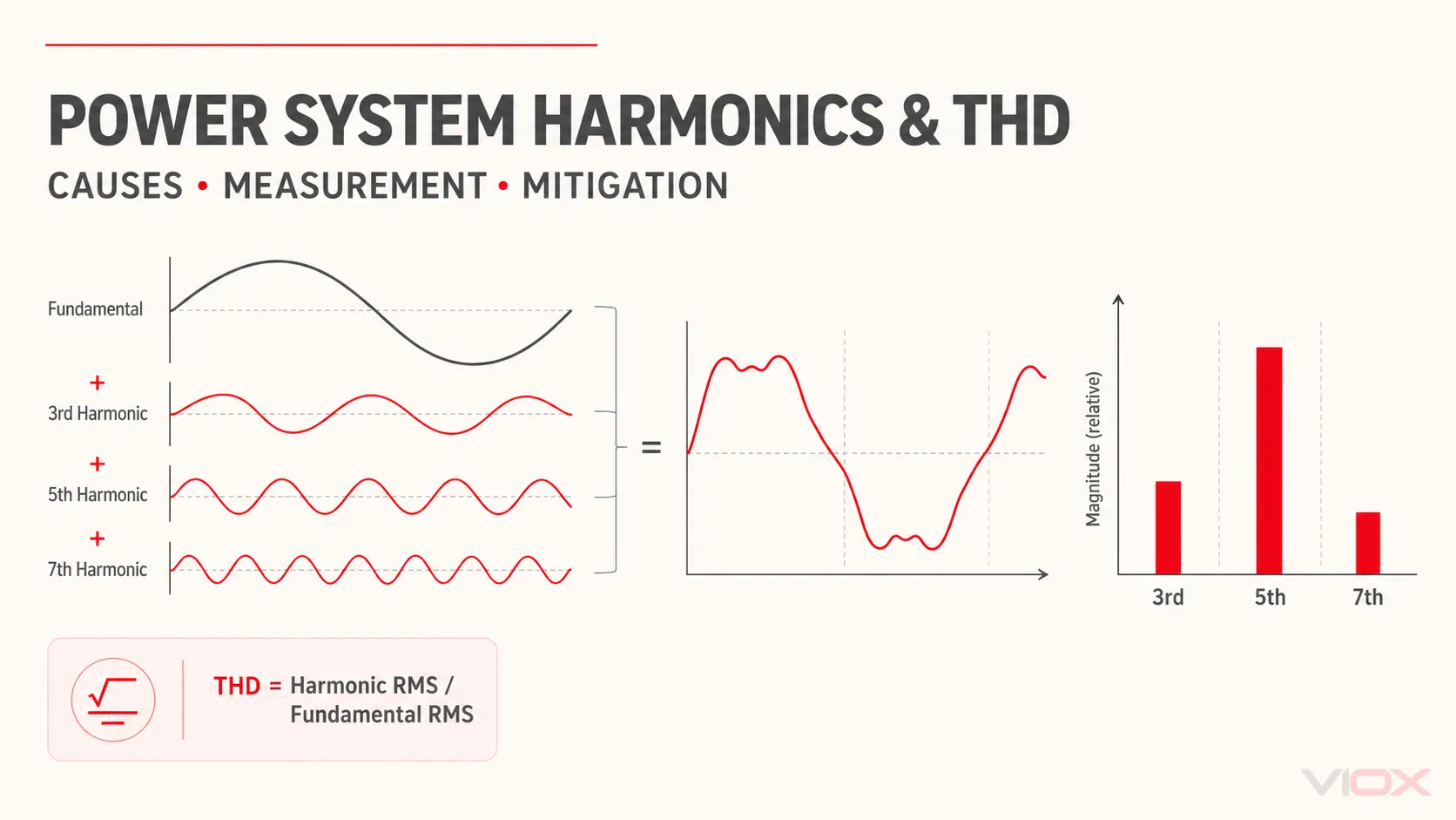
Ang mga harmonic sa sistemang elektrikal ay mga component ng boltahe o kuryente na ang mga frequency ay integer multiple ng fundamental power frequency. Sa isang 50 Hz na sistema, ang ika-3 harmonic ay 150 Hz at ang ika-5 ay 250 Hz; sa isang 60 Hz na sistema, ang mga ito ay 180 Hz at 300 Hz. Ang mga component na ito ay humahalo sa fundamental waveform at nagiging sanhi upang lumayo ang boltahe o kuryente sa isang ideal na sine wave.
Total harmonic distortion (THD) ay pinagsasama ang kabuuang harmonic content sa isang porsyento. Ito ay kapaki-pakinabang para sa screening, pag-trending, at paghahambing ng mga sukat, ngunit ang halaga ng THD lamang ay hindi tumutukoy sa pinagmulan, dominanteng harmonic order, compliance point, o tamang lunas. Ang isang mapangangatwirang pagsusuri ay dapat maghiwalay sa voltage distortion mula sa current distortion, kumpirmahin kung saan kinuha ang sukat, suriin ang harmonic spectrum, at tasahin ang instalasyon sa ilalim ng mga representatibong kondisyon ng karga.
Mga Pangunahing Takeaway
- Ang mga nonlinear load ay lumilikha ng harmonic current dahil humihigop sila ng kuryente nang pa-pulso sa halip na ayon sa proporsyon ng inilapat na boltahe.
- Ang harmonic current na dumadaloy sa system impedance ay lumilikha ng harmonic voltage distortion.
- Ang THDv, THDi, at total demand distortion (TDD) ay gumagamit ng magkakaibang numerator o reference value at hindi dapat ituring na mapagpapalit.
- Ang IEEE 519 ay naglalapat ng mga layunin para sa steady-state voltage at current distortion sa point of common coupling (PCC) ng gumagamit, hindi bilang isang unibersal na limitasyon ng pass/fail para sa bawat terminal ng device.
- Ang mataas na pagbabasa ng THDi sa light load ay maaaring nakalilito dahil maliit ang denominator ng fundamental-current; ang TDD ay nagbibigay ng demand-based reference para sa pagtatasa ng PCC.
- Dapat sumunod ang mitigation sa pagsukat. Ang mga reactor, passive filter, active harmonic filter, multipulse rectifier, at active-front-end drive ay lumulutas ng iba't ibang problema.
- Ang isang standard na power-factor-correction capacitor bank ay hindi awtomatikong harmonic filter at maaaring magdulot ng panganib ng resonance kung gagamitin nang walang harmonic study.
Harmonics, THD, at TDD sa Isang Tingin
| Dami | Ano ang inilalarawan nito | Reference value | Pinakamahusay na paggamit | Karaniwang pagkakamali sa interpretasyon |
|---|---|---|---|---|
| Indibidwal na harmonic | Magnitude ng isang harmonic order, gaya ng ika-5 | Fundamental o iba pang nakasaad na reference | Pagkilala sa mga dominanteng source at pagpili ng mga filter | Pagtingin lamang sa THD at pagkawala ng isang dominanteng order |
| THDv | Pinagsamang harmonic voltage distortion | Fundamental voltage | Pagtatasa sa kalidad ng waveform sa isang bus o terminal ng kagamitan | Paglalapat ng isang limitasyon sa boltahe sa bawat lokasyon |
| THDi | Pinagsamang harmonic current distortion | Pangunahing (fundamental) current sa sandali ng pagsukat | Pagtatasa sa isang load at pagsubaybay sa gawi ng operasyon nito | Paghahambing ng THDi sa light-load at full-load nang walang konteksto |
| TDD | Pinagsamang harmonic current na may kaugnayan sa demand current | Maximum demand load current, IL | IEEE 519-style current assessment at the PCC | Itinuturing ito bilang isa pang pangalan para sa THDi |
| Harmonic spectrum | Magnitude ng bawat nasukat na harmonic order | Fundamental o reference ng instrumento | Pag-diagnose sa pinagmulan at pagpili ng mitigasyon | Paggamit ng iisang kabuuang halaga nang hindi sinusuri ang mga order |
Ano ang Lumilikha ng mga Harmonic sa isang Sistemang Elektrikal?
Ang linear load ay humihila ng current waveform na malawak na proporsyonal sa inilapat na boltahe. Ang mga resistance heater ay isang simpleng halimbawa. Ang isang nonlinear load ay nagbabago ng impedance sa bawat cycle o gumagamit ng switching at rectification, kaya ang current nito ay hinihila nang pabaligtad (pulses) o putol-putol na segments. Kinakatawan ng Fourier analysis ang distorted periodic waveform na iyon bilang isang fundamental component kasama ang mga harmonic component.
Ang frequency ng harmonic order h ay:
fh = h x f1

kung saan:
fh = harmonic frequency
h = harmonic order: 2, 3, 4, 5...
f1 = fundamental frequency: karaniwang 50 Hz o 60 Hz
Ang mga karaniwang load na nagdudulot ng harmonic ay kinabibilangan ng:
- six-pulse variable frequency drives (VFDs) at iba pang rectifier load;
- uninterruptible power supplies (UPSs);
- switched-mode power supplies sa mga computer, server, at kagamitang pang-control;
- LED drivers at electronic lighting ballast;
- mga battery charger at kagamitan sa pag-charge ng de-kuryenteng sasakyan;
- mga kagamitan sa welding, arc furnace, at iba pang nonlinear na prosesong industriyal;
- mga saturated magnetic na kagamitan sa ilalim ng hindi normal na mga kondisyon ng operasyon.
Ang load ay karaniwang nagpapasok muna ng harmonic current. Habang dumadaloy ang current na iyon sa transformer, cable, busbar, at source impedance, lumilikha ito ng mga harmonic voltage drop. Ang resultang voltage distortion ay maaaring makaapekto sa iba pang kagamitang nakakonekta sa parehong bus. Mahalaga ang pagkakaibang ito dahil ang pagpapalit ng sensitibong load ay hindi nag-aalis ng source sa antas ng system, habang ang paglalagay ng filter sa maling bus ay maaaring magdulot ng kaunting pagbabago lamang.
Paano Pinupuwersa ng mga Harmonic ang Isang AC Waveform
Ang isang ideal na sinusoidal waveform ay naglalaman lamang ng fundamental frequency. Ang isang totoong nonlinear load ay maaaring humatak ng fundamental current kasama ang ika-3, ika-5, ika-7, at mas mataas na order na mga component. Sa bawat sandali, ang mga component na ito ay nagsasama-sama nang alhebraiko. Ang resulta ay maaaring magmukhang flat-topped, matulis ang tuktok, may uka (notched), o kung hindi man ay distorted kahit na ang RMS voltage ay mukhang malapit sa nominal.
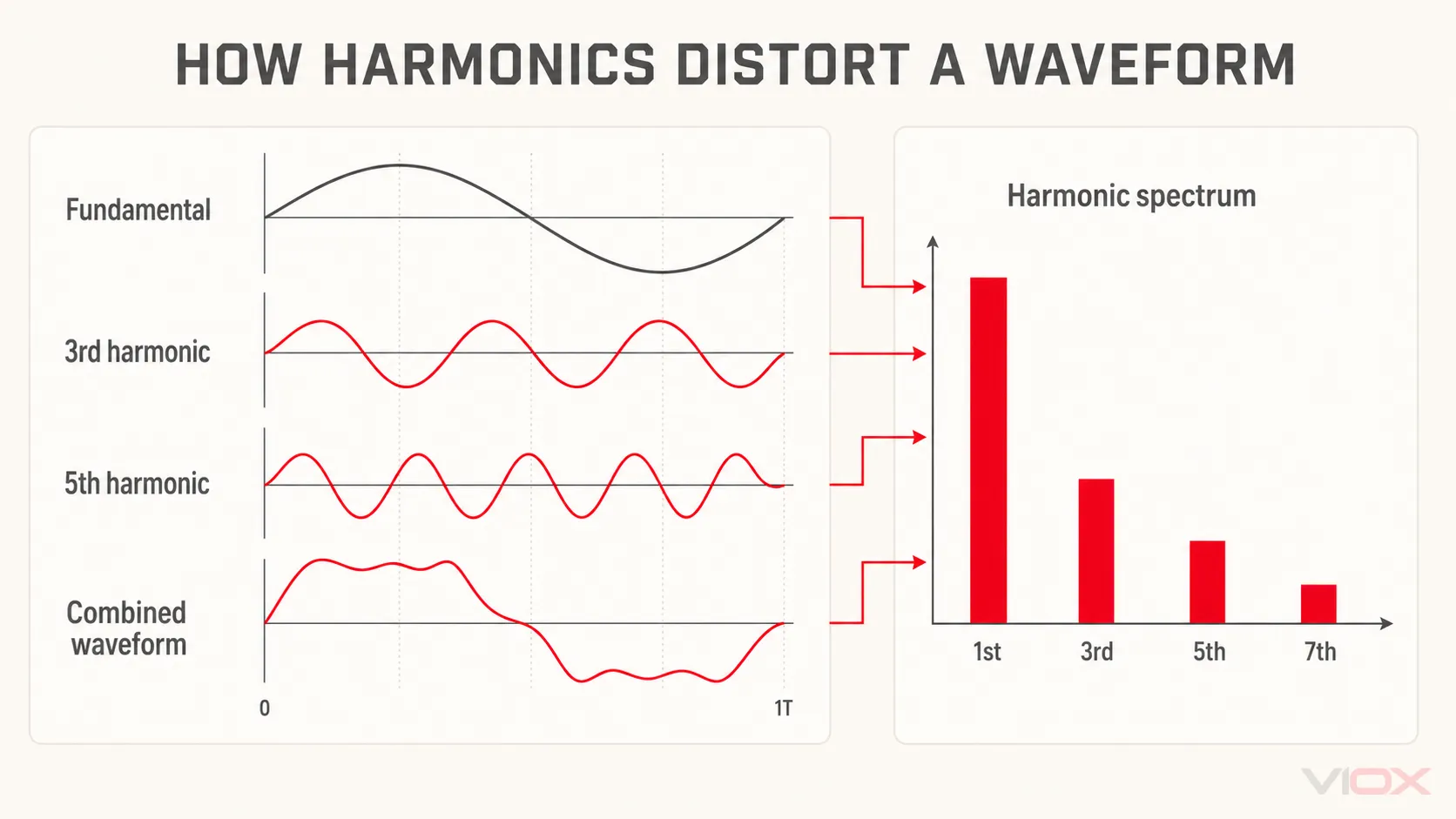
Ang hugis at spectrum ng waveform ay nagbibigay ng magkakaibang impormasyon:
- Ang time-domain waveform ay nagpapakita ng notching, flat-topping, mataas na crest factor, at switching behavior.
- Ipinapakita ng frequency-domain spectrum kung aling mga harmonic order ang nangingibabaw.
- Nagbibigay ang THD ng isang maginhawang kabuuan, ngunit hindi nito maipakita kung ang distortion ay pangunahing ika-3, ika-5, ika-7, o nakakalat sa maraming order.
Para sa disenyo ng mitigasyon, ang spectrum ay karaniwang mas nagagamit kaysa sa kabuuan lamang.
Paano Kinakalkula ang Total Harmonic Distortion?
Voltage THD
Ang Voltage THD ay ang root-sum-square na halaga ng mga harmonic voltage na hinati sa fundamental voltage:
THDv = [sqrt(V2^2 + V3^2 + ... + Vh^2) / V1] x 100%

V1 = RMS fundamental voltage
Vh = RMS voltage ng harmonic order h
Ipinapahiwatig ng THDv kung gaano kalayo ang waveform ng boltahe sa punto ng pagsukat mula sa fundamental component nito. Ito ay naiimpluwensyahan ng harmonic current at ng impedance sa pagitan ng source at ng punto ng pagsukat.
Current THD
Ang Current THD ay gumagamit ng parehong istruktura ngunit ibinabatay ang harmonic current sa fundamental current na sinusukat sa oras na iyon:
THDi = [sqrt(I2^2 + I3^2 + ... + Ih^2) / I1] x 100%

I1 = RMS fundamental current sa sandali ng pagsukat
Ih = RMS current ng harmonic order h
Ang THDi ay kapaki-pakinabang kapag sinusuri ang gawi ng isang indibidwal na nonlinear load. Gayunpaman, ang resulta ay maaaring tumaas nang husto sa mababang load dahil I1 ay nagiging maliit, kahit na ang absolute harmonic current ay wala sa pinakamalalang kondisyon ng sistemang elektrikal. Palaging itala ang load current at operating state sa tabi ng THDi.
Total Demand Distortion
Ang TDD ay ibinabatay ang harmonic current sa isang demand-current value sa halip na sa instant na fundamental current:
TDD = [sqrt(I2^2 + I3^2 + ... + Ih^2) / IL] x 100%

IL = maximum demand load current sa PCC, na tinukoy para sa angkop na paraan ng pagtatasa
Dahil sa mas stable na denominator na ito, ang TDD ay angkop para sa pagtatasa kung paano nauugnay ang harmonic current ng isang pasilidad sa demand nito sa PCC. Ang tamang IL, aggregation interval, observation period, at short-circuit ratio ay dapat sumunod sa naaangkop na standard at pag-aaral ng proyekto. Huwag gumamit ng breaker rating, transformer nameplate current, o anumang madaling pagsukat nang walang sapat na dahilan.
Bakit Maaaring Magkaiba ang Sinasabi ng THDv at THDi
Ang mataas na current distortion ay hindi awtomatikong nangangahulugan ng mataas na voltage distortion. Ang isang matatag na sistemang elektrikal na may mababang source impedance ay maaaring humigop ng malaking harmonic current habang pinapanatiling malinis ang voltage waveform. Ang isang mahinang sistema o mahabang feeder na may mataas na impedance ay maaaring makaranas ng mas malaking voltage distortion mula sa mas maliit na harmonic current.
Ang kabaligtarang diagnostic distinction ay kapaki-pakinabang din:
- Ang mataas na THDi sa isang branch ngunit katanggap-tanggap na THDv sa main bus ay madalas na tumutukoy sa isang lokal na nonlinear load na may limitadong epekto sa sistema.
- Ang mataas na THDv sa ilang feeder ay nagpapahiwatig ng distortion sa isang karaniwang upstream bus o isang kondisyon ng resonance.
- Ang mataas na THDv sa service entrance bago pa man gumana ang mga pangunahing load ng site ay maaaring magpahiwatig ng kontribusyon mula sa upstream na nangangailangan ng imbestigasyon sa panig ng utility.
- Ang mataas na THDi sa panahon lamang ng isang partikular na mode ng operasyon ay tumuturo sa isang source na dulot ng proseso, gaya ng drive loading, rectifier conduction, o operasyon ng charger.
Ano-anong Problema ang Maaaring Idulot ng Harmonics?
Ang harmonics ay walang iisang unibersal na sintomas. Ang epekto nito ay nakadepende sa harmonic order, magnitude, impedance ng sistemang elektrikal, pattern ng load, ayos ng grounding, resonance, at disenyo ng kagamitan.
Karagdagang Pag-init sa mga Conductor, Busbar, at Transformer
Ang harmonic current ay nagpapataas ng kabuuang RMS current at samakatuwid ay ang pag-init ng conductor. Ang mga bahagi na may mas mataas na frequency ay nagpapataas din ng eddy-current at skin-effect losses sa mga magnetic at conductive na bahagi. Ang mga transformer na nagbibigay ng supply sa malalaking nonlinear load ay maaaring makaranas ng karagdagang winding at stray losses kahit pa ang average na kW demand ay mukhang normal.
Ang mga koneksyong apektado na ng mataas na resistance ay lalong bulnerable dahil ang distorted na RMS current ay nakakadagdag sa I²R pag-init. Ang mga diagnostic method sa gabay ng VIOX para sa sobrang pag-init ng terminal block makakatulong na ihiwalay ang harmonic loading mula sa maluwag o sira nang mga koneksyon.
Sobrang pag-init ng Neutral-Conductor
Sa isang balanseng three-phase, four-wire na sistemang elektrikal, ang mga fundamental current ng magkakatulad na single-phase load ay malaking bahagi na nagka-cancel sa neutral. Ang mga triplen harmonic, kabilang ang ika-3, ika-9, at ika-15, ay mga zero-sequence component at maaaring magdagdag sa neutral sa halip na mag-cancel. Samakatuwid, ang isang balanseng pagbasa ng phase-current ay hindi garantiyang mababa ang neutral current.
Ang neutral loading ay dapat sukatin nang direkta kung saan nakapokus ang mga elektronikong single-phase load. Huwag ipagpalit ang function ng neutral sa pagdadala ng current sa protective earth path; ang pagkakaiba nito ay ipinaliwanag sa neutral bar laban sa grounding bar.
Mga Pagkalugi sa Motor, Torque Pulsation, at Ingay
Ang mga voltage harmonic ay lumilikha ng mga rotating magnetic field sa iba't ibang bilis at direksyon. Sa mga induction motor, ang ilang harmonic sequence ay sumasalungat sa fundamental rotating field, habang ang iba naman ay nagpapatibay sa direksyon nito sa iba't ibang synchronous speed. Ang resulta ay maaaring kabilang ang karagdagang pagkalugi sa copper at iron, torque pulsation, vibration, naririnig na ingay, at nabawasang magagamit na thermal margin.
Kapag may mga drive, paghiwalayin ang line harmonics sa input-side mula sa PWM voltage stress sa output-side. Ang isang line reactor o input harmonic filter ay tumutugon sa ibang problema kumpara sa output reactor, sine-wave filter, o dV/dt filter. Ang gabay sa VFD laban sa soft starter ay nagbibigay ng mas malawak na konteksto sa motor-control.
Sobrang Karga sa Capacitor at Resonance
Ang mga capacitor para sa power-factor-correction ay nagbabawas ng demand sa reactive power sa fundamental frequency, ngunit ang impedance ng mga ito ay bumababa habang tumataas ang frequency. Kapag pinagsama sa inductance ng sistemang elektrikal, maaari silang lumikha ng parallel o series resonance malapit sa isang umiiral na harmonic order. Ang resulta nito ay maaaring magpalakas ng harmonic voltage o current at magdulot ng sobrang karga sa mga capacitor, reactor, transformer, o switching device.
Samakatuwid, ang isang conventional capacitor bank ay hindi dapat ituring bilang unibersal na lunas sa harmonic. Kung ang harmonic content ay makabuluhan, ang disenyo ay maaaring mangailangan ng mga detuned reactor, isang tuned passive filter, isang active harmonic filter, o iba pang inihandang solusyon. Ang layunin at hangganan ng automatic power-factor correction ay tinalakay sa Buong kahulugan at operasyon ng APFC.
Hindi kinakailangang pag-andar (Nuisance Operation) at Maling Paggana ng Elektroniko
Ang mga distorted na waveform ay maaaring magpataas ng peak current, magbago ng zero crossings, magdagdag ng init, at makagambala sa mga kagamitang umaasa sa suplay na malapit sa sinusoidal. Ang mga posibleng sintomas ay kinabibilangan ng hindi maipaliwanag na paggana ng protective-device, mga alarma sa capacitor-stage, ingay sa transformer, pag-reset ng control, maling pagbasa mula sa mga hindi angkop na instrumento, at nabawasang buhay ng kagamitan.
Ang mga sintomas na ito ay hindi patunay ng harmonics. Ang mga maluwag na conductor, hindi balanseng boltahe, transients, sobrang karga (overload), electromagnetic interference, at maling mga setting ay maaaring magmukhang katulad nito. Kinakailangan ang pagsukat bago pumili ng lunas.
Saan at Paano Dapat Sukatin ang Harmonics?
Ang plano sa pagsukat ay dapat sumagot sa isang tiyak na tanong: pagsunod sa PCC, pag-troubleshoot ng kagamitan, pagtukoy sa pinagmulan, pagpaplano ng kapasidad, o pagpapatunay pagkatapos ng mitigation. Bihirang masagot ng isang spot measurement ang lahat ng lima.
1. Tukuyin ang Hangganan ng Pagsukat (Measurement Boundary)
Para sa assessment ng IEEE 519 sa antas ng pasilidad, tukuyin ang contractual o engineering PCC. Para sa internal na pag-troubleshoot, magsukat din sa in-plant point of coupling, main distribution bus, hinihinalang feeder, at mga load terminal kung kinakailangan. I-dokumento ang one-line diagram at ang lokasyon ng bawat pagbasa.
2. Gumamit ng Angkop na Instrumentation
Gumamit ng power-quality analyzer na may kakayahang sabay-sabay na sumukat ng three-phase voltage at current, harmonic spectrum capture, THDv, THDi, TDD kung kinakailangan, event logging, at pagsukat ng neutral-current para sa mga four-wire system. Ang IEC 61000-4-7 ay tumatalakay sa harmonic at interharmonic measurement instrumentation, habang ang IEC 61000-4-30 ay tumutukoy sa mga pamamaraan ng pagsukat ng power-quality at mga klase ng pagsukat.
Ang isang basic average-responding meter ay hindi sapat para sa pag-diagnose ng mga distorted waveform. Ang isang true-RMS meter ay maaaring magpabuti sa katumpakan ng RMS current at voltage, ngunit karaniwan ay hindi nito napapalitan ang isang power-quality analyzer para sa harmonic order, trend, direksyon, at pagsusuri ng pagsunod sa mga pamantayan.
3. Kumuha ng Kinakatawang Kondisyon ng Operasyon
Itala ang mga sukat sa iba't ibang operating state sa halip na umasa lamang sa isang snapshot:
- minimum, normal, at maximum na karga ng pasilidad;
- drive acceleration, steady operation, at mga kondisyon ng mababang bilis;
- mga operating mode ng UPS o charger;
- ang mga stage ng capacitor-bank na binubuksan at isinasara;
- operasyon ng generator at utility kung saan posible ang pareho;
- mga siklo ng produksiyon na nauugnay sa mga reklamo o sobrang karga (overheating).
4. Itala ang Konteksto sa Bawat THD Value
Bilang minimum, itala ang:
- lokasyon ng pagsukat at konfigurasyon ng sistemang elektrikal;
- boltahe ng phase-to-phase at phase-to-neutral kung naaangkop;
- RMS current ng phase at neutral;
- THDv, THDi, at TDD kung naaangkop;
- indibidwal na harmonic spectrum at mga phase value;
- kW, kVA, kvar, power factor, at load state;
- status ng source transformer, conductor, at capacitor-bank;
- timestamp at logging interval.
5. Bakasin ang Source nang Sistematiko
Magsimula sa assessment point at ihambing ang mga reading sa upstream at downstream. Kung tumaas nang husto ang distortion kapag may isang feeder na naka-energize, magpatuloy patungo sa branch na iyon. Kung ang ilang feeder ay nagpapakita ng katulad na voltage distortion, imbestigahan ang common bus, capacitor resonance, o upstream source.
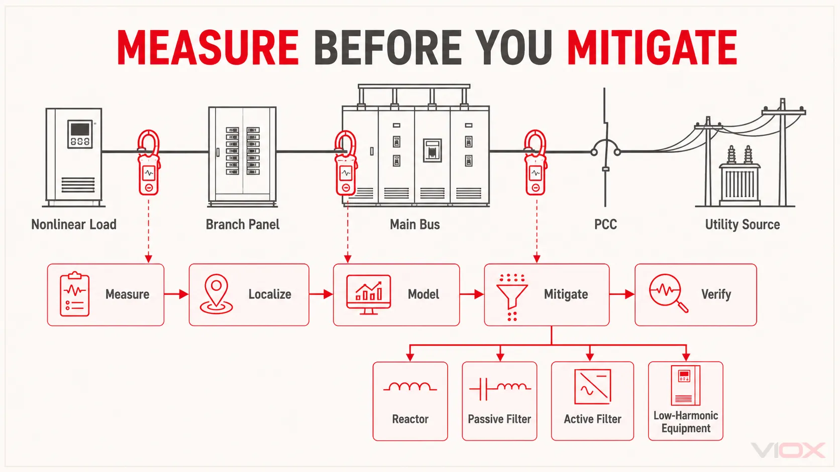
Ang tamang pagkakasunod-sunod ay sukatin, hanapin, imodelo, pagaanin, at i-verify. Ang paglalagay ng filter bago itatag ang baseline na ito ay maaaring magtago ng isang sintomas habang iniiwang hindi nagbabago ang aktwal na pinagmulan o resonance.
Paano Naaangkop ang mga Pamantayan sa Harmonics
| Sanggunian | Pangunahing papel | Praktikal na hangganan |
|---|---|---|
| IEEE 519-2022 | Mga layunin para sa distortion ng boltahe at current ng sistemang elektrikal | Ipinapatupad sa PCC ng gumagamit sa ilalim ng mga tinukoy na kondisyong steady-state; ang mga limitasyon ng current ay nakadepende sa konteksto ng sistema, kabilang ang lakas ng short circuit kaugnay ng demand |
| IEC 61000-4-7 | Instrumentasyon para sa pagsukat ng harmonic at interharmonic | Tinutukoy kung paano pinapangkat at sinusukat ang mga spectral component para sa pagtatasa ng kagamitan at sistemang elektrikal |
| IEC 61000-4-30:2025 | Mga paraan ng pagsukat ng kalidad ng kuryente na In-situ | Tinutukoy ang mga paulit-ulit na paraan at mga approach na Class A/Class S para sa mga parameter kabilang ang voltage at current harmonics |
| IEC 61000-2-4:2024 | Mga antas ng compatibility sa mga industriyal na sistemang elektrikal ng pamamahagi ng kuryente | Nalalapat sa point of coupling sa loob ng planta at hinahati ang mga industriyal na electromagnetic environment sa mga tinukoy na klase |
| IEC 61000-3-2 / IEC 61000-3-12 | Mga limitasyon sa harmonic-current emission para sa mga tinukoy na kategorya ng kagamitan | Mga pamantayan sa antas ng kagamitan na may tinukoy na saklaw; hindi ito pamalit sa komprehensibong pagtatasa ng PCC sa pasilidad |
Tatlong panuntunan upang maiwasan ang mga karaniwang pagkakamali sa pamantayan:
- Kumpirmahin ang punto ng pagtatasa. Ang limitasyon sa PCC ay hindi awtomatikong limitasyon sa input ng VFD o sa isang malayong branch panel.
- Kumpirmahin ang denominator at ang paraan ng pagkuha ng average. Ang THDi at TDD ay maaaring makagawa ng magkaibang porsyento mula sa parehong current spectrum.
- Kumpirmahin ang naaangkop na edisyon at saklaw ng kagamitan. Ang mga kinakailangan ng utility, mga espesipikasyon ng proyekto, mga grid code ng rehiyon, at mga pamantayan ng produkto ay maaaring magdagdag ng mga obligasyon na higit pa sa isang pangkalahatang gabay.
Aling Pamamaraan sa Pagpapagaan ng Harmonic ang Dapat Mong Gamitin?
Walang unibersal na pinakamahusay na filter. Piliin ang pamamaraan batay sa source spectrum, load variability, system impedance, kinakailangang performance, magagamit na espasyo, mga pagkalugi (losses), kakayahan sa pagpapanatili, at pagpapalawak sa hinaharap.
| Sitwasyon | Mga opsyon sa pagpapagaan na susuriin | Mga konsiderasyong pang-inhinyero |
|---|---|---|
| Isang conventional na six-pulse drive | AC line reactor, DC choke, passive harmonic filter, low-harmonic drive, o active-front-end drive | Kinakailangang pagbabawas, saklaw ng load, voltage drop, episyensya, footprint, pagsasaayos ng bypass |
| Ilang nonlinear load na may nagbabagong demand | Central o distributed active harmonic filter | Lokasyon ng CT, compensation current, mga harmonic order, load diversity, expansion margin |
| Stable na dominanteng harmonic order | Tuned o broadband na passive filter | Network impedance, tuning tolerance, capacitor duty, resonance, operasyon ng generator |
| Power-factor correction sa isang distorted na network | Detuned capacitor bank o engineered filter bank | Umiiral na spectrum, resonance frequency, capacitor current, switching duty, mga setting ng controller |
| Mataas na triplen harmonic current sa isang four-wire system | Bawasan ang source emissions, muling ipamahagi ang mga load, gumamit ng angkop na pag-filter, at suriin ang disenyo ng neutral/transformer | Pagsukat ng neutral current, thermal capacity ng conductor, pagiging angkop ng transformer, hinaharap na electronic load |
| Bagong proyekto na may malaking pangangailangan sa rectifier | Multipulse rectifier, phase-shifting transformer, active front end, o tinukoy na low-harmonic equipment | Lakas ng source, redundancy, pagiging kumplikado ng transformer, lifecycle cost, target na pagsunod |
| Ang umiiral na kagamitan ay nag-o-overheat na | Pagbabawas ng load at kontrol sa panganib ng init bago ang permanenteng mitigasyon | Harmonic survey, inspeksyon ng koneksyon, bentilasyon, kundisyon ng conductor at transformer |
Line Reactors at DC Chokes
Ang mga reactor ay nagdaragdag ng impedance at nagpapatag ng current na hinihila ng mga rectifier load. Ang mga ito ay relatibong simple at matibay, ngunit ang resulta ng mga ito ay nakadepende sa source impedance at disenyo ng drive. Binabawasan nito ang harmonic current sa halip na alisin ito at nagdudulot ng voltage drop at mga kawalan (losses).
Passive Harmonic Filters
Ang mga passive filter ay pinagsasama ang mga inductor at capacitor upang magbigay ng low-impedance path para sa mga napiling harmonic frequency o broadband attenuation. Maaari silang maging epektibo para sa stable at predictable na mga load, ngunit dapat silang idisenyo base sa aktwal na network. Ang detuning, component tolerances, pagkakaiba-iba ng load, at pakikipag-ugnayan sa mga generator o iba pang capacitor bank ay nangangailangan ng pagsusuri.
Active Harmonic Filters
Ang isang active harmonic filter ay sumusukat ng distortion at naglalabas ng compensating current. Mas umaangkop ito sa nagbabagong load profile at kayang patamaan ang maraming harmonic order, ngunit ang kasalukuyang kapasidad, pagkakaayos ng CT, pagtugon, enclosure, mga pagkalugi (losses), at mga layunin sa kontrol nito ay dapat na tukuyin.
Low-Harmonic Drive at Active Front End
Ang mga arkitektura ng low-harmonic drive ay nagbabawas ng distortion sa pinagmulan sa halip na mag-compensate para sa ilang load sa isang common bus. Maaari nitong gawing simple ang isang bagong instalasyon ngunit nakakaapekto ito sa gastos, footprint, mga pagkalugi (losses), electromagnetic compatibility, at estratehiya sa pagpapanatili. Ang kakayahang mag-regenerate at ang mababang harmonic distortion ay magkahiwalay na requirement kahit pa ang isang produkto ay nag-aalok ng pareho.
Praktikal na Workflow para sa Pagsusuri ng Harmonic
- Tukuyin ang reklamo at boundary. Tukuyin ang sobrang pag-init, nuisance operation, pagsunod sa pamantayan (compliance), pagpapalawak, o maling paggana ng kagamitan bilang pangunahing problema.
- Suriin ang one-line diagram at load inventory. Markahan ang mga nonlinear load, capacitor bank, generator, transformer, at mahahabang feeder.
- Magtatag ng baseline sa PCC o main bus. I-log ang boltahe, current, demand, THD/TDD, at ang harmonic spectrum.
- I-trace ang mga dominanteng order patungo sa mga branch load. Ihambing ang mga pagbabago habang nag-a-cycle ang mga pangunahing load.
- Suriin ang resonance at impedance ng sistemang elektrikal. Isama ang data ng transformer at capacitor-bank sa pag-aaral.
- Pumili ng kandidatong mitigation. Ihambing ang source reduction, passive filtering, active filtering, at mga hakbang sa equipment withstand.
- Inaasahang pagganap ng model. Suriin ang normal, minimum, maximum, utility, at generator na mga estado ng operasyon.
- Ipatupad nang may proteksiyon at thermal design. I-coordinate ang mga conductor, switching device, bentilasyon, at proteksiyon ng filter.
- Ulitin ang mga orihinal na sukat. I-verify ang pagpapabuti sa parehong lokasyon at maihahambing na mga estado ng load.
Mga Karaniwang Pagkakamali sa Pagtatasa ng Harmonic
Pagtrato sa Bawat Porsiyento ng THD Bilang Parehong Dami
Laging lagyan ng label ang value bilang THDv, THDi, o TDD at itala ang denominator nito. Ang percentage na walang kasamang nasukat na dami at lokasyon ay hindi kumpletong data.
Pagsukat Lamang sa Nonlinear Load
Ang pagsukat sa load-terminal ay naglalarawan sa load ngunit hindi nito itinatatag ang pagsunod ng pasilidad o epekto sa PCC. Magsukat sa parehong lokasyon kung kinakailangan.
Paggamit ng THD Nang Walang Harmonic Spectrum
Ang dalawang sistemang elektrikal ay maaaring magkaroon ng parehong THD ngunit nangangailangan ng magkaibang mitigation dahil magkaiba ang kanilang dominant orders. Panatilihin ang indibidwal na harmonic data.
Pag-install ng mga Capacitor Nang Hindi Sinusuri ang Resonance
Maaaring ilipat ng mga capacitor ang resonance ng network patungo sa isang umiiral na harmonic. Suriin ang harmonic content at impedance bago magdagdag o magpalawak ng power-factor correction.
Pag-aakalang Tinatanggal ng isang SPD ang mga Harmonic
Ang isang SPD ay naglilimita ng transient overvoltage ayon sa disenyo nito; hindi nito patuloy na sinasala ang low-order power-frequency harmonics. Ang harmonics at surges ay nangangailangan ng magkaibang pagsusuri at mga panukalang proteksiyon. Para sa transient-protection boundary, tingnan ang kung ano ang ginagawa ng isang surge protective device.
Pagturing sa isang Mas Malaking Neutral o Transformer bilang Source Mitigation
Ang kagamitang may matibay na thermal ay maaaring mas makatagal sa harmonic loading, ngunit hindi nito awtomatikong binabawasan ang harmonic injection o voltage distortion. Paghiwalayin ang mga hakbang sa withstand mula sa pagbabawas ng emission.
Madalas Na Tinatanong Na Mga Katanungan
Ano ang pagkakaiba ng harmonics at THD?
Ang harmonics ay ang mga indibidwal na frequency component sa integer multiples ng fundamental frequency. Ang THD ay isang porsyento na kumakatawan sa root-sum-square magnitude ng mga harmonic component na iyon kaugnay sa isang itinakdang reference.
Ang THD ba ay sinusukat sa boltahe o sa kuryente?
Maaari itong sukatin sa alinman. Ang THDv ay naglalarawan ng voltage waveform distortion, habang ang THDi ay naglalarawan ng current waveform distortion. Ang dami ay dapat na malinaw na nakasaad dahil magkakaiba ang mga sanhi, limitasyon, at interpretasyon nito.
Bakit mukhang napakataas ng current THD sa light load?
Hinahati ng THDi ang harmonic current sa pamamagitan ng instantaneous fundamental current. Sa mababang load, lumiliit ang fundamental denominator, kaya ang porsyento ay maaaring tumaas kahit na ang absolute harmonic current ay hindi tumaas. Suriin ang magnitude ng current, spectrum, at TDD kung naaangkop.
Ano ang pagkakaiba ng THDi at TDD?
Ibinabatay ng THDi ang harmonic current sa fundamental current sa sandali ng pagsukat. Ibinabatay naman ito ng TDD sa tinukoy na maximum demand load current. Dahil dito, mas stable ang TDD para sa pagsusuri ng PCC sa gitna ng nagbabagong kondisyon ng load.
Lagi bang pinapataas ng harmonics ang neutral current?
Hindi sa bawat sistemang elektrikal. Ang pag-aalala ay pinakamalaki sa mga three-phase, four-wire system na nagtutustos sa maraming single-phase nonlinear load, kung saan ang mga triplen harmonic current ay maaaring mag-add sa neutral. Sukatin nang direkta ang neutral sa halip na ipagpalagay ang cancellation.
Maaari bang bawasan ng capacitor bank ang THD?
Kapag lamang ito idinisenyo bilang bahagi ng harmonic filtering o detuned compensation system. Ang isang standard na capacitor bank ay maaaring hindi makabawas ng THD at maaari pang magpalala ng distortion kung ito ay mag-resonate sa inductance ng sistemang elektrikal.
Nagfi-filter ba ng harmonics ang isang surge protector?
Hindi. Ang SPD ay tumutugon sa transient overvoltage. Ang mga harmonic ay mga steady-state o paulit-ulit na waveform component na nangangailangan ng source reduction, reactor, harmonic filter, o iba pang hakbang para sa kalidad ng kuryente.
Saan dapat kunin ang mga sukat para sa IEEE 519?
Itinatakda ng IEEE 519 ang mga layunin para sa steady-state distortion sa user point of common coupling. Ang aktwal na PCC ay dapat matukoy base sa pagkakaayos ng serbisyo at proyekto sa halip na ipagpalagay na ito ay bawat terminal ng kagamitan.
Anong instrumento ang kailangan para sukatin ang THD?
Gumamit ng power-quality analyzer na angkop para sa layunin ng pagtatasa at may kakayahang mag-record ng three-phase voltage, current, harmonic spectrum, THD, at TDD kapag kinakailangan. Ang isang true-RMS multimeter ay kapaki-pakinabang para sa tumpak na mga RMS value sa mga distorted na waveform ngunit karaniwang hindi nito kayang magsagawa ng kumpletong harmonic study.
Konklusyon
Ang harmonic assessment ay hindi paghahanap ng isang katanggap-tanggap na numero ng THD. Ito ay isang organisadong pagsisiyasat sa mga waveform component, lokasyon ng pagsukat, lakas ng sistemang elektrikal, gawi ng load, at interaksyon ng kagamitan.
Magsimula sa pamamagitan ng pagtukoy sa pagkakaiba ng THDv, THDi, at TDD. Magsukat sa tamang boundary sa ilalim ng mga kinatawang operating condition, itabi ang indibidwal na harmonic spectrum, at bakasin ang mga dominanteng order patungo sa kanilang mga pinagmulan. Pagkatapos, pumili ng mitigation na tumutugma sa network: mga reactor para sa impedance at smoothing, passive filter para sa mga predictable na spectrum, active filter para sa mga nagbabagong load, o low-harmonic na kagamitan kapag ang source reduction ang mas mainam na desisyon para sa sistemang elektrikal.
Para sa mga panel builder at OEM, ang pinakamahalagang specification ay hindi lamang ang “low THD.” Ito ay isang tiyak na kinakailangan sa performance na nakatali sa PCC o terminal ng kagamitan, saklaw ng operating load, naaangkop na standard, paraan ng pagsukat, at pamamaraan ng pagpapatunay.
Mga Sanggunian
- IEEE 519-2022: Pamantayan para sa Harmonic Control sa mga sistemang elektrikal ng kuryente
- IEC 61000-4-7: Mga sukat at instrumentasyon para sa harmonics at interharmonics
- IEC 61000-4-30:2025: Mga pamamaraan sa pagsukat ng kalidad ng kuryente
- IEC 61000-2-4:2024: Mga antas ng compatibility sa mga sistemang elektrikal para sa distribusyon ng kuryente sa industriya
- Schneider Electric: Mga konsiderasyon sa kalidad ng kuryente
- ABB Technical Guide No. 6: Gabay sa harmonics na may AC drives
- Fluke: Pag-troubleshoot ng power harmonics