Sa pahinang ito
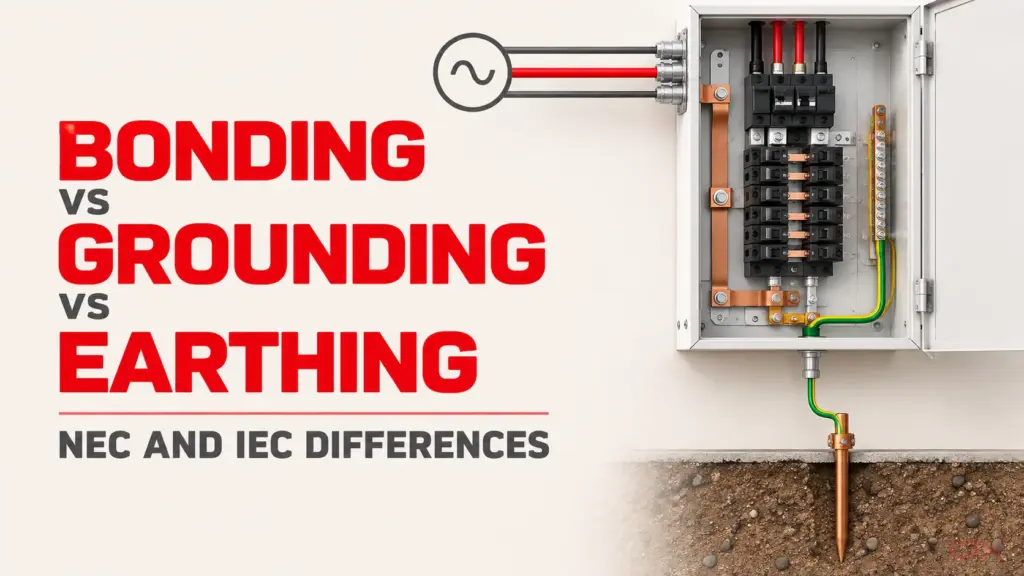
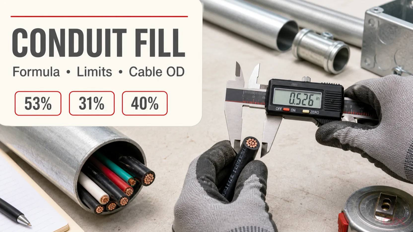
Ang porsyento ng conduit fill ay ang kabuuang cross-sectional area ng mga conductor at cable sa loob ng isang raceway na hinati sa internal cross-sectional area ng raceway, at pinarami ng 100. Sa ilalim ng karaniwang framework ng National Electrical Code (NEC) Chapter 9, ang normal na maximum fill ay 53% para sa isang conductor o cable, 31% para sa dalawa, at 40% para sa higit sa dalawa. Ang isang kwalipikadong conduit o tubing nipple na hindi lalampas sa 24 inches ay maaaring gumamit ng 60% na limitasyon. Palaging i-verify ang edisyon ng NEC na pinagtibay ng authority having jurisdiction (AHJ) at ang mga tala na naaangkop sa instalasyon.
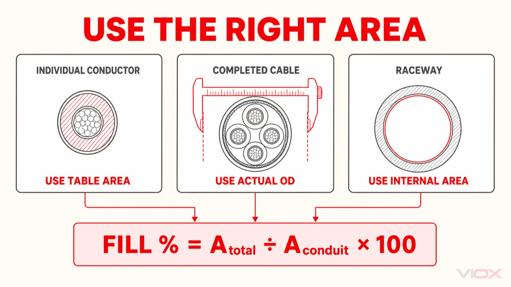
Ang mismong pagkalkula ay simple. Karamihan sa mga pagkakamali ay nagmumula sa pagpili ng maling area: paggamit ng copper area ng conductor sa halip na area ng insulated-conductor, paggamit ng nominal conduit trade size bilang internal diameter nito, o paggamit ng generic na diameter ng cable sa halip na eksaktong outside diameter (OD) mula sa manufacturer.
Formula ng Conduit Fill
Para sa isang bilog na cable o conductor na may outside diameter d:
A = π × d² ÷ 4Para sa ilang grupo ng conductor o cable:
A_total = Σ(n × A_item)Ang porsyento ng punan ng conduit ay:
Fill % = A_total ÷ A_conduit × 100saan:
| Simbolo | Ibig sabihin | Gamitin |
|---|---|---|
d |
Tapos na panlabas na diameter | Gamitin para sa isang bilog na kumpletong cable kapag ibinigay ng manufacturer ang OD |
A_item |
Area ng isang conductor o cable | Gamitin ang naaangkop na code table o kalkulahin mula sa beripikadong OD |
n |
Dami ng conductor o cable na iyon | Bilangin ang bawat item na pisikal na sumasakop sa raceway |
A_total |
Kabuuan ng lahat ng sinasakop na area | Idagdag ang bawat grupo ng conductor at cable |
A_conduit |
Kabuuang internal na area ng raceway | Gamitin ang value para sa eksaktong uri ng raceway at trade size |
Panatilihin ang lahat ng dimensyon sa parehong unit. Kung ang diameter ay nasa inches, ang makukuhang area ay nasa square inches. Kung ang diameter ay nasa millimetres, ang area ay nasa square millimetres. Dahil ang fill ay isang ratio, gagana ang alinmang unit system kung gagamitin ito nang consistent.
Mga Limitasyon sa NEC Conduit Fill
Ang NEC Chapter 9 Table 1 ay nagtatakda ng mga pamilyar na limitasyon sa porsyento na ginagamit sa United States. Nalalapat ang mga ito sa internal cross-sectional area ng raceway, hindi sa nominal trade-size number nito.
| Mga nilalaman o kondisyon ng raceway | Sanggunian para sa maximum fill |
|---|---|
| Isang conductor o cable | 53% |
| Dalawang conductor o cable | 31% |
| Higit sa dalawang conductor o cable | 40% |
| Qualifying nipple na hindi lalampas sa 24 in | 60% |
Ang mga figure na ito ay hindi unibersal na internasyonal na mga panuntunan. Ang mga proyekto sa labas ng framework ng NEC ay dapat gumamit ng naaangkop na pambansang mga panuntunan sa wiring, espesipikasyon ng proyekto, at mga kinakailangan ng lokal na awtoridad. Kahit sa mga proyekto ng NEC, suriin ang lahat ng naaangkop na tala sa Chapter 9 at ang artikulong namamahala sa napiling raceway.
Ang isang multiconductor cable, optical-fiber cable, o flexible cord ay karaniwang itinuturing na isang conductor para sa mga layunin ng percentage-fill. Para sa isang elliptical na cable, gamitin ang paraan ng area na itinakda ng code batay sa major dimension nito sa halip na ipagpalagay na ang minor dimension nito ang diameter ng cable. Ang isang assembly ng mga indibidwal na insulated conductor na walang panlabas na takip ay hindi awtomatikong itinuturing na isang cable; kalkulahin ang mga indibidwal na conductor ayon sa kinakailangan ng mga pinagtibay na panuntunan.
Piliin ang Tamang Area Bago Magkalkula
Ang sumusunod na input map ay pumipigil sa tatlong pinakakaraniwang pagkakamali sa pagkalkula.
| Aytem na ikinakabit | Tamang source ng area | Huwag magpalit |
|---|---|---|
| Indibidwal na insulated na wire para sa gusali, gaya ng THHN/THWN-2 | Naaangkop na talahanayan ng area ng insulated-conductor para sa pinagtibay na edisyon ng code at konstruksiyon ng conductor | Area ng hubad na tanso mula sa pagtatalaga ng AWG o mm² |
| Round multiconductor, control, data, coaxial, o fiber cable | Tapos na OD ng cable mula sa manufacturer, na kinonvert sa area | Laki ng conductor, generic na average sa catalogue, o laki ng connector |
| Elliptical o flat na cable | Paraang kinakailangan ng naaangkop na code, na karaniwang gumagamit ng pangunahing dimensyon bilang epektibong circular diameter | Minor diameter lamang |
| EMT, RMC/GRC, PVC, o iba pang raceway | Nakalistang internal area para sa eksaktong pamilya ng raceway at trade size | Nominal trade size na itinuturing bilang inside diameter |
Mga Indibidwal na Conductor: Gamitin ang Nakalistang Insulated Area
Ang isang AWG o mm² designation ay naglalarawan ng laki ng conductor; hindi nito kasama ang kapal ng nakabit na insulation. Ang dalawang conductor na may parehong copper area ay maaaring sumakop ng magkaibang raceway area dahil magkaiba ang kanilang mga uri ng insulation o konstruksiyon. Para sa isang kalkulasyon ng NEC, gamitin ang naaangkop na halaga mula sa Chapter 9 Table 5 o iba pang talahanayan na kinakailangan para sa eksaktong konstruksiyon ng conductor.
Ang Annex C ay maaaring magpabilis ng kalkulasyon kapag ang lahat ng conductor ay pareho ang laki at uri. Kapag ang mga laki ng conductor o uri ng insulation ay magkakaiba, gamitin ang batayang Chapter 9 area method sa halip na pumili ng hindi kaugnay na lookup para sa parehong laki.
Mga Nakumpletong Cable: Kontrol sa OD ng Manufacturer
Para sa isang nakumpletong cable, kunin ang nominal o maximum na OD mula sa eksaktong datasheet ng produkto. Ang jacket, mga screen, filler, armor, bedding, at tolerance sa pagmamanupaktura ang nagtatakda ng espasyong kinakain ng cable. Sukatin ang cable kapag hinihingi ito ng gabay sa pag-install o kapag ang aktwal na produkto ay maaaring magkaiba nang malaki sa nakaplanong halaga.
Ang VIOX Conduit Fill Calculator ay may kasamang mga karaniwang preset ng cable-OD para sa paunang pagpaplano at nagpapahintulot ng paglalagay ng custom na OD. Ang data ng manufacturer para sa napiling cable ay laging mas matimbang kaysa sa generic na preset.
Laki ng Raceway: Gamitin ang Internal Area, Hindi ang Trade-Size Label
Ang isang 1-inch na conduit ay walang 1.000-inch na inside diameter. Nagkakaiba ang mga internal na dimensyon sa pagitan ng electrical metallic tubing (EMT), rigid metal conduit (RMC/GRC), PVC Schedule 40, PVC Schedule 80, at iba pang raceway. Gamitin ang entry sa talahanayan para sa eksaktong pamilya ng raceway at trade size.
Step-by-Step na Kalkulasyon ng Conduit Fill
Gamitin ang pagkakasunod-sunod na ito para sa mga installation na may parehong laki, magkakaibang laki, o mga nakumpletong cable:
- Tukuyin ang mga umiiral na panuntunan. Itala ang hurisdiksyon, pinagtibay na edisyon ng code, artikulo ng raceway, at kung ang run ay kwalipikado para sa anumang espesyal na kondisyon gaya ng nipple rule.
- Ilista ang lahat ng nasa loob ng raceway. Itala ang bawat uri ng conductor o cable, insulation o konstruksyon, dami, at pinagmulan ng dimensyon.
- Kunin ang bawat nasasakupang area. Gamitin ang naaangkop na conductor table o kalkulahin ang area ng round cable mula sa beripikadong OD.
- I-multiply ang area sa dami. Gawin ito nang hiwalay para sa bawat grupo.
- Idagdag ang lahat ng mga grupo. Ang resulta ay
A_total. - Kunin ang internal area ng raceway. Gamitin ang eksaktong uri at trade size.
- Kalkulahin ang fill percentage. I-divide
A_totalsa pamamagitan ngA_conduit, pagkatapos ay i-multiply sa 100. - Ilapat ang tamang limit. Ipaghambing sa 53%, 31%, 40%, 60%, o sa iba pang limitasyong kinakailangan ng mga namamahalang tuntunin.
- Lakihan ang laki ng raceway kung kinakailangan. Ulitin ang kalkulasyon gamit ang internal area ng susunod na kandidato. Huwag i-round down ang resultang hindi pumasa.
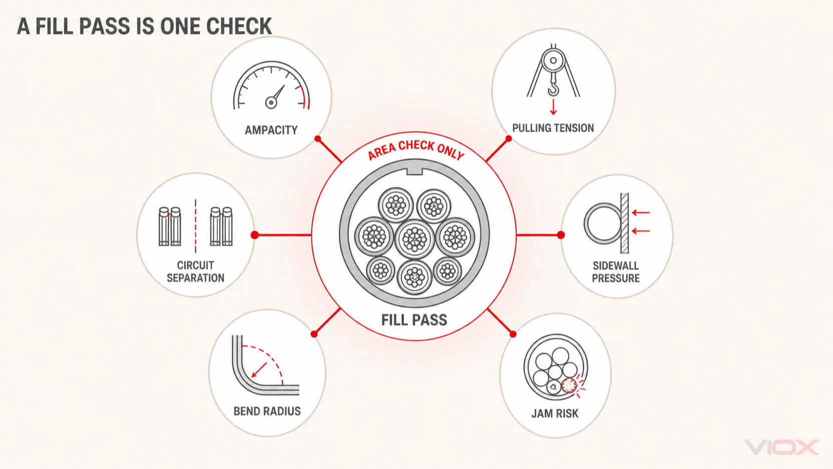
- Tapusin ang magkakahiwalay na pagsusuring pang-inhinyero. Kumpirmahin ang adjustment ng ampacity, bend radius, pulling tension, sidewall pressure, panganib ng cable-jam, paghihiwalay, grounding, at mga detalye ng instalasyon.
Halimbawang Gawain 1: Siyam na Indibidwal na Konduktor na Magkakapareho ang Laki
Ipagpalagay ang isang kalkulasyon ayon sa NEC para sa siyam na 12 AWG THHN na konduktor sa 3/4-inch EMT. Para sa halimbawang ito, ang mga pinagtibay na halaga sa table ay:
- area ng isang 12 AWG THHN na konduktor:
0.0133 in²; - kabuuang internal area ng 3/4-inch EMT:
0.533 in²; - naaangkop na limitasyon para sa higit sa dalawang conductor:
40%.
Hakbang 1: Kalkulahin ang Kabuuang Area ng Conductor
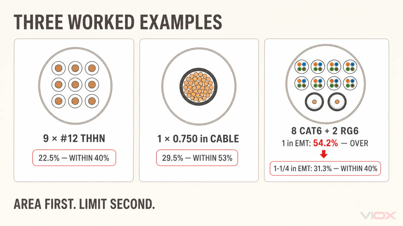
A_total = 9 × 0.0133 = 0.1197 in²Hakbang 2: Kalkulahin ang Fill Percentage
Fill % = 0.1197 ÷ 0.533 × 100 = 22.5%Hakbang 3: Ihambing sa Limitasyon
Ang pinakamataas na pinapayagang area sa 40% ay:
A_allowed = 0.533 × 0.40 = 0.2132 in²Dahil ang 0.1197 in² ay mas mababa sa 0.2132 in², at ang 22.5% ay mas mababa sa 40%, ang kombinasyon ay pumasa sa kalkulasyon ng area-fill.
Ang resultang ito ay hindi kumukumpleto sa pag-size ng conductor. Ang bilang ng mga conductor na may daloy ng kuryente ay maaaring mag-trigger ng adjustment sa ampacity, at ang bilang na iyon ay tinutukoy sa ilalim ng ibang mga panuntunan kumpara sa mga pisikal na item na binibilang para sa raceway fill.
Halimbawang Gawa 2: Isang Multiconductor Cable Gamit ang Aktwal na OD
Ipagpalagay ang isang bilog na multiconductor cable na may OD na inilathala ng manufacturer na 0.750 in na naka-install sa 1-1/4-inch EMT. Gamitin ang inside diameter ng EMT na 1.380 in para sa halimbawang ito ng transparent geometry.
Hakbang 1: Kalkulahin ang Area ng Cable
A_cable = π × 0.750² ÷ 4 = 0.4418 in²Hakbang 2: Kalkulahin ang Raceway Area
A_conduit = π × 1.380² ÷ 4 = 1.4957 in²Hakbang 3: Kalkulahin ang Fill Percentage
Fill % = 0.4418 ÷ 1.4957 × 100 = 29.51%Ang isang multiconductor cable ay itinuturing na isang cable para sa paghahambing ng porsyentong ito, kaya ang limitasyon ng sanggunian ay 53%. Sa 29.51%, ang kombinasyon ay pumasa sa area-fill check.
Bago tanggapin ang installation, kumpirmahin na ang OD ng manufacturer ay naaangkop sa eksaktong konstruksyon ng cable at ang mga dimensyon ng raceway ay tumutugma sa governing table. I-verify din ang minimum bend radius at pulling limits; ang isang malaking cable ay maaaring pumasa sa fill ngunit mahirap o hindi angkop na i-install sa rutang may ilang mga liko.
Worked Example 3: Mixed Cable ODs at ang Susunod na Passing Raceway
Ipagpalagay na ang isang low-voltage pathway ay naglalaman ng:
- walong Cat6 cable, na ang bawat isa ay
0.236 inOD; - dalawang RG6 coaxial cable, na ang bawat isa ay
0.275 inOD.
Ang mga OD na ito ay mga planning input para sa halimbawa. Gamitin ang aktwal na dimensyon ng napiling mga manufacturer para sa isang proyekto.
Hakbang 1: Kalkulahin ang Area ng Bawat Grupo
Isang Cat6 cable:
A_Cat6 = π × 0.236² ÷ 4 = 0.0437 in²Walong Cat6 cable:
8 × 0.0437 = 0.3499 in²Isang RG6 cable:
A_RG6 = π × 0.275² ÷ 4 = 0.0594 in²Dalawang RG6 cable:
2 × 0.0594 = 0.1188 in²Kabuuang nasasakupang area:
A_total = 0.3499 + 0.1188 = 0.4687 in²Hakbang 2: Suriin ang 1-Inch EMT
Gamit ang internal area na humigit-kumulang 0.8643 in²:
Fill % = 0.4687 ÷ 0.8643 × 100 = 54.2%Ang sampung cable ay nangangailangan ng reference limit na higit sa dalawa na 40%, kaya hindi pumasa ang 1-inch EMT.
Hakbang 3: Suriin ang 1-1/4-Inch EMT
Gamit ang internal area na humigit-kumulang 1.4957 in²:
Fill % = 0.4687 ÷ 1.4957 × 100 = 31.31%Ang 1-1/4-inch EMT ay pumasa sa 40% area-fill check. Nagbibigay din ito ng mas malaking margin para sa paghila at kapasidad sa hinaharap kumpara sa raceway na pinili nang eksakto sa maximum.
Ang halimbawang ito ay tumatalakay lamang sa pisikal na area. Kumpirmahin ang mga pinapayagang kombinasyon ng cable, mga kinakailangan sa paghihiwalay, firestopping, suporta, bend radius, at anumang panuntunan sa sistemang pang-komunikasyon na naaangkop sa instalasyon.
Suriin ang Resulta gamit ang VIOX Conduit Fill Calculator
Gamitin ang calculator upang ikumpara ang EMT, RMC/GRC, PVC Schedule 40, at PVC Schedule 80, maglagay ng dalawang grupo ng cable o custom na OD, at tukuyin ang unang trade size na pumasa sa loob ng napiling pamilya ng raceway.
Ang calculator na ito ay isang paunang tulong sa pagpaplano. I-verify ang mga input nito laban sa eksaktong mga datasheet ng cable, ang ginamit na edisyon ng code, ang listahan ng raceway, at ang mga kinakailangan ng AHJ bago ang pagbili o pag-install.
Ano ang Hindi Pinapatunayan ng Resulta ng Passing Fill
Ang conduit fill ay sumasagot sa isang tanong: gaano kalaking bahagi ng internal cross-sectional area ng raceway ang nasasakop? Hindi nito pinapatunayan na ang mga conductor ay may sapat na ampacity o na ang mga cable ay maaaring i-install nang walang pinsala.
| Hiwalay na pagsusuri | Bakit ito nananatiling kinakailangan |
|---|---|
| Pagsasaayos ng ampacity | Ang maraming conductor na may daloy ng kuryente sa loob ng isang raceway ay maaaring mangailangan ng pagsasaayos kahit na ang pisikal na fill ay nasa ibaba ng limitasyon |
| Pagbaba ng boltahe | Hindi ipinapakita ng area ng raceway kung ang resistance ng conductor ay katanggap-tanggap para sa load at haba ng takbo nito |
| Pulling tension | Ang haba ng cable, mga liko, friction, paraan ng paghila, at konstruksyon ng conductor ang nagtatakda ng tensile stress |
| Sidewall pressure | Maaaring masira ang isang cable kung saan ang pulling tension ay kumikilos sa paligid ng isang liko |
| Panganib ng pagkaipit ng cable | Ang tatlo o higit pang magkakatulad na cable ay maaaring maipit sa mga liko kahit na nasa ibaba pa ito ng maximum area fill |
| Minimum bend radius | Maaaring magkasya ang isang cable sa loob ng raceway ngunit hindi kayang sundin ang ruta nang hindi lumalagpas sa limitasyon ng pagbaluktot nito |
| Mga panuntunan sa paghihiwalay at sistemang elektrikal | Ang mga circuit para sa power, control, komunikasyon, fire-alarm, at optical-fiber ay maaaring may karagdagang mga kinakailangan sa pagruruta |
| Spare capacity | Ang disenyo na nasa code-maximum ay maaaring mag-iwan ng maliit na praktikal na espasyo para sa paghila o mga susunod na dagdag |
Ang gabay sa pag-install ng cable ng Southwire ay tumutukoy sa jam ratio bilang panloob na diameter ng conduit na hinati sa OD ng cable at tinutukoy ang isang karaniwang rehiyon ng panganib para sa tatlong magkakatulad na cable. Ituring ito bilang input sa pagsusuri ng paghila, hindi bilang kapalit ng naaangkop na code, data ng manufacturer ng cable, o kalkulasyon ng paghila na partikular sa ruta.
Para sa pagpili ng conductor na lampas sa pisikal na area ng pathway, gamitin ang VIOX guide para sa IEC cable sizing, voltage drop, derating, at trunking capacity. Para sa mga kalkulasyon ng long-run loss, tingnan ang voltage drop at line-loss guide. Ang mga ito ay magkakahiwalay na gawaing disenyo at hindi dapat ipagpalagay mula sa resulta ng conduit-fill.
Checklist para sa Pag-verify ng Conduit Fill
Bago aprubahan ang laki ng raceway, i-verify ang lahat ng sumusunod:
- ang hurisdiksyon ng proyekto at ang pinagtibay na edisyon ng wiring-code;
- ang eksaktong pamilya ng raceway, trade size, at internal area;
- uri ng insulation ng conductor at naaangkop na table area;
- tagagawa ng completed-cable, part number, konstruksiyon, at aktwal na OD;
- pagtrato sa multiconductor, elliptical, o bundled assemblies;
- ang tama, isa, dalawa, higit-sa-dalawa, o qualifying-nipple limit;
- arithmetic para sa bawat grupo ng cable at unit conversion;
- ampacity adjustment at mga limitasyon sa temperatura ng conductor;
- bilang ng liko, bend radius, pulling tension, sidewall pressure, at panganib ng pagkaipit (jam risk);
- paghihiwalay ng circuit, grounding, sealing, firestopping, at mga kinakailangan sa kapaligiran;
- praktikal na margin sa paghila at nakaplanong kapasidad sa hinaharap.
Kung may anumang input na hindi tiyak, huwag lutasin ang kawalan ng katiyakan sa pamamagitan ng pag-round down. Kunin ang eksaktong data ng conductor, cable, at raceway, pagkatapos ay ulitin ang kalkulasyon o gamitin ang VIOX conduit fill calculator upang i-verify ang binagong kombinasyon.