
Circuit breakers are critical protective devices in electrical systems, designed to interrupt fault currents and prevent damage to equipment and infrastructure. While many assume that electric arcs are unwanted phenomena in circuit breaker operation, the reality is quite different. In AC systems, controlled electric arcs play an essential role in safe and effective current interruption. Understanding the four key processes of circuit breaker disconnection reveals why arc management, rather than arc elimination, is fundamental to modern electrical protection.
Why Electric Arcs Are Necessary in Circuit Breaker Operation
Many engineers intuitively believe that eliminating electric arcs would improve circuit breaker performance. However, in AC systems, attempting to “hard cut” current without an arc creates dangerous consequences. When contacts separate abruptly without arc formation, the magnetic energy stored in inductive loads has nowhere to dissipate. This energy instantaneously transfers to stray capacitance, creating hazardous overvoltages that can cause insulation failure and re-striking phenomena.
A controlled electric arc functions as a manageable switch, allowing load energy to return orderly to the power source. The arc provides a conductive path until the AC current naturally reaches zero, at which point extinction occurs under favorable conditions. The circuit breaker must then withstand the transient recovery voltage (TRV) to complete safe system reset.
The Four Key Processes of Circuit Breaker Disconnection
Process 1: Contact Separation and Arc Establishment
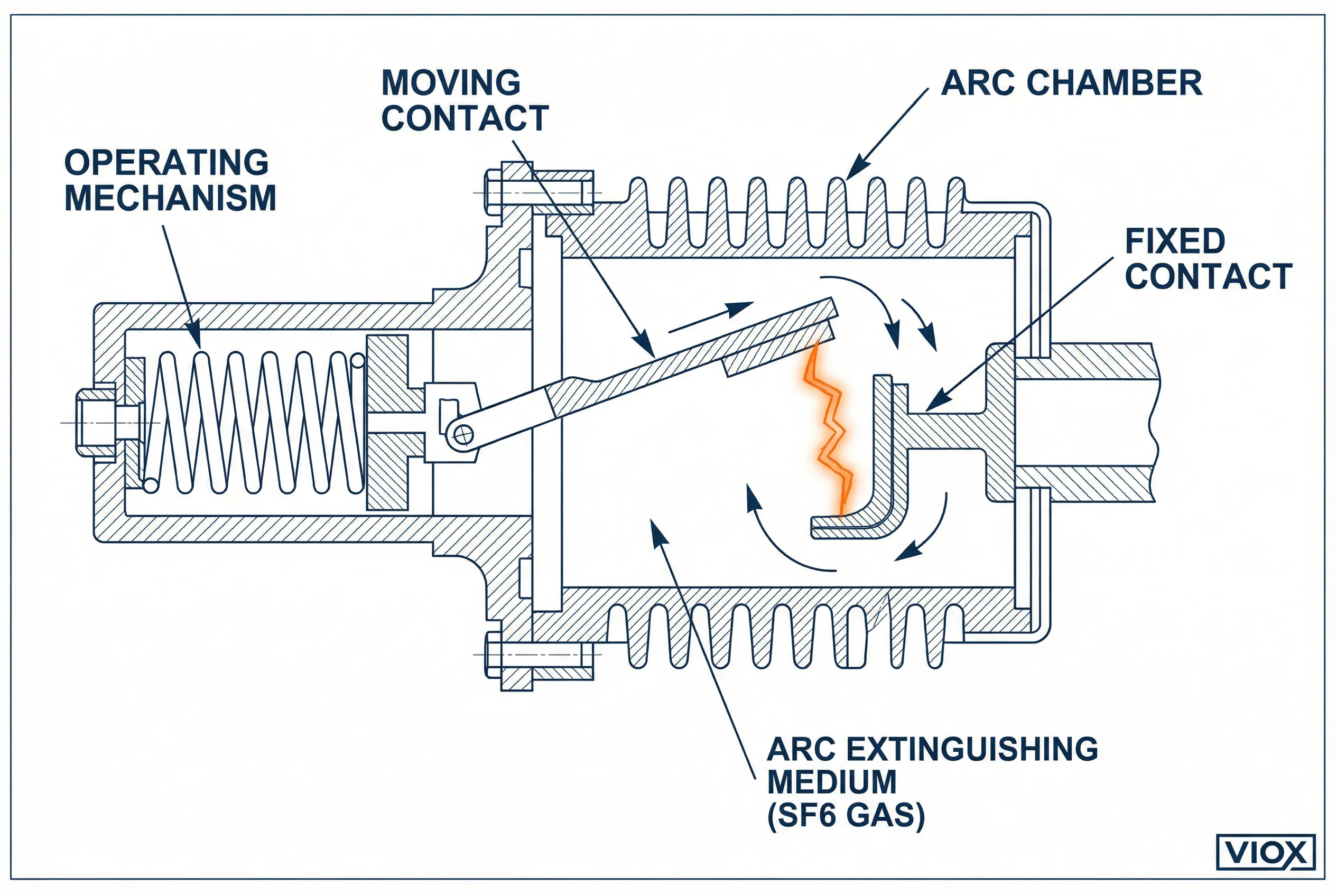
When circuit breaker contacts initially separate, a microscopic contact bridge remains between them. At this junction, current density becomes extremely high, causing contact material to undergo melting, vaporization, and ionization. This process creates a plasma channel—the electric arc—within the arc-extinguishing medium (air, oil, SF₆ gas, or metal vapor in vacuum).
The arc establishment phase doesn’t represent system failure; rather, it channels energy into a manageable conductive pathway, preventing immediate voltage spikes. During this stage, the circuit breaker creates sufficient contact gap distance and establishes cooling conditions necessary for subsequent arc extinction. The plasma channel temperature can reach 20,000°C (36,000°F), making proper arc chamber design critical for safe operation.
Process 2: Arc Maintenance and Energy Return
During the arc maintenance phase, current continues flowing through the arc plasma while magnetic energy from inductive loads gradually returns to the power source. Modern circuit breakers employ various techniques to manage this process:
- Gas or oil blast systems create high-velocity flows that cool and disperse ionized particles
- Magnetic blow mechanisms elongate and split the arc using electromagnetic forces
- Vacuum environments enable rapid metal vapor diffusion and cooling
- Arc chutes divide the arc into multiple smaller segments for enhanced cooling
The circuit breaker must maintain the arc for a minimum duration while achieving sufficient contact separation. This minimum arc time varies by system voltage and current magnitude, but typically ranges from 8-20 milliseconds at 50 Hz. Inadequate arc time or insufficient contact gap results in re-striking when voltage recovery occurs.
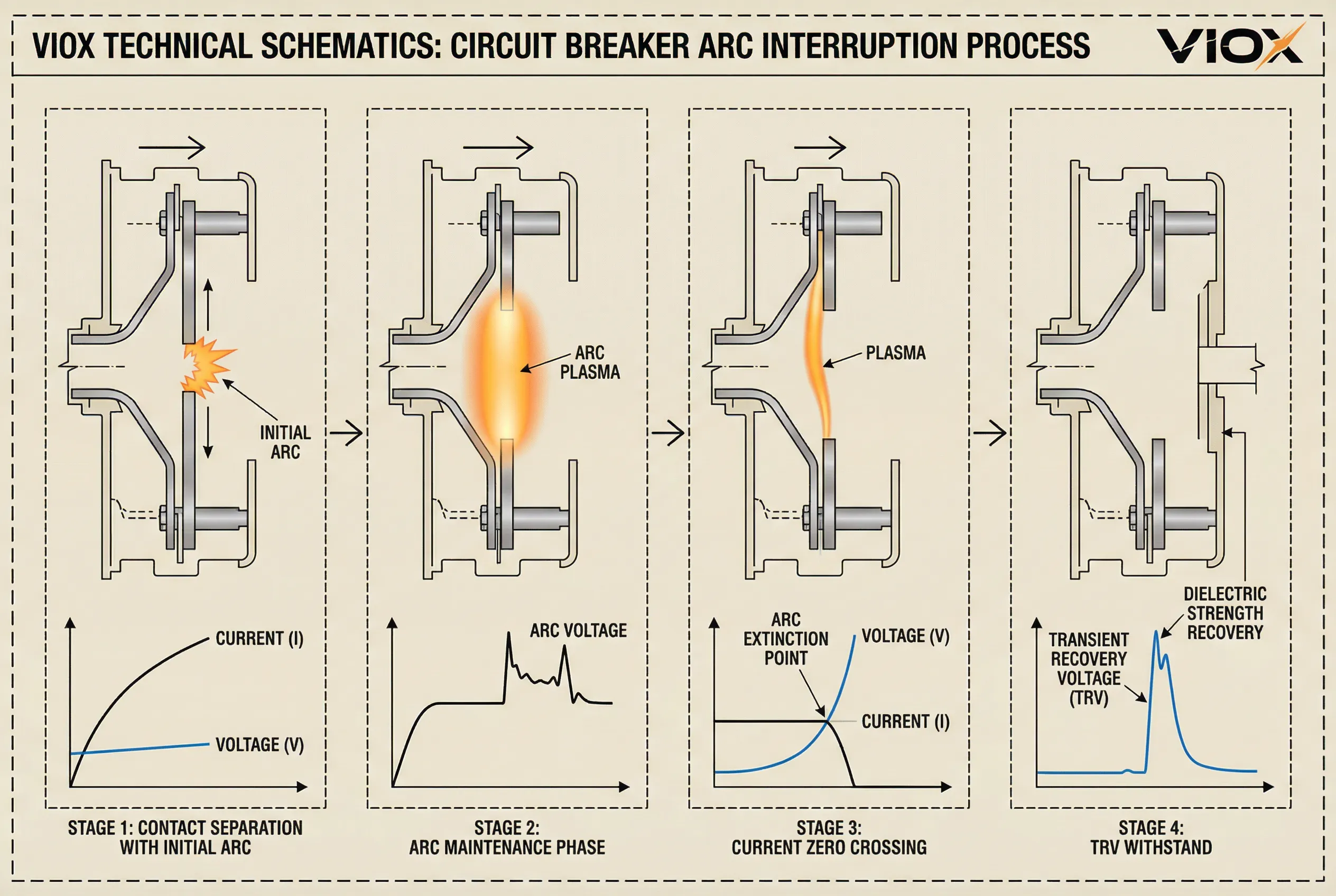
Process 3: Current Zero Crossing and Arc Extinction
As AC current approaches its natural zero crossing, properly cooled contacts with adequate separation enable rapid arc de-ionization. The dielectric strength between contacts recovers quickly—up to 20 kV/μs in vacuum circuit breakers—allowing arc extinction at the current zero point.
This critical moment determines interruption success. The arc doesn’t extinguish when contacts initially separate; true current interruption occurs only at current zero with successful de-ionization. Several factors influence first-crossing extinction success:
- Contact opening velocity and travel distance
- Arc-extinguishing medium properties and flow characteristics
- Contact material composition and thermal properties
- System voltage and current magnitudes
- Temperature and pressure conditions within arc chamber
Circuit breakers designed for high short-circuit currents incorporate advanced arc-splitting technologies and enhanced cooling mechanisms to ensure reliable extinction at the first current zero crossing.
Process 4: TRV Withstand and Voltage Recovery
Immediately after arc extinction, transient recovery voltage (TRV) appears across the open contacts. This voltage results from superposition of source-side and load-side components, typically exhibiting multi-frequency oscillatory behavior. The TRV waveform characteristics include:
- Rate of Rise of Recovery Voltage (RRRV): Initial voltage increase rate, measured in kV/μs
- Peak TRV amplitude: Maximum voltage stress on open contacts
- Frequency components: Multiple oscillation frequencies from system inductances and capacitances
Circuit breakers must withstand TRV within standardized limits (IEC 62271-100, IEEE C37.04) to prevent re-striking. If dielectric recovery is incomplete when TRV peaks, arc re-ignition occurs, potentially causing catastrophic failure. As transient oscillations decay, voltage stabilizes at power-frequency recovery voltage (RV), completing the interruption sequence and enabling immediate system re-energization.
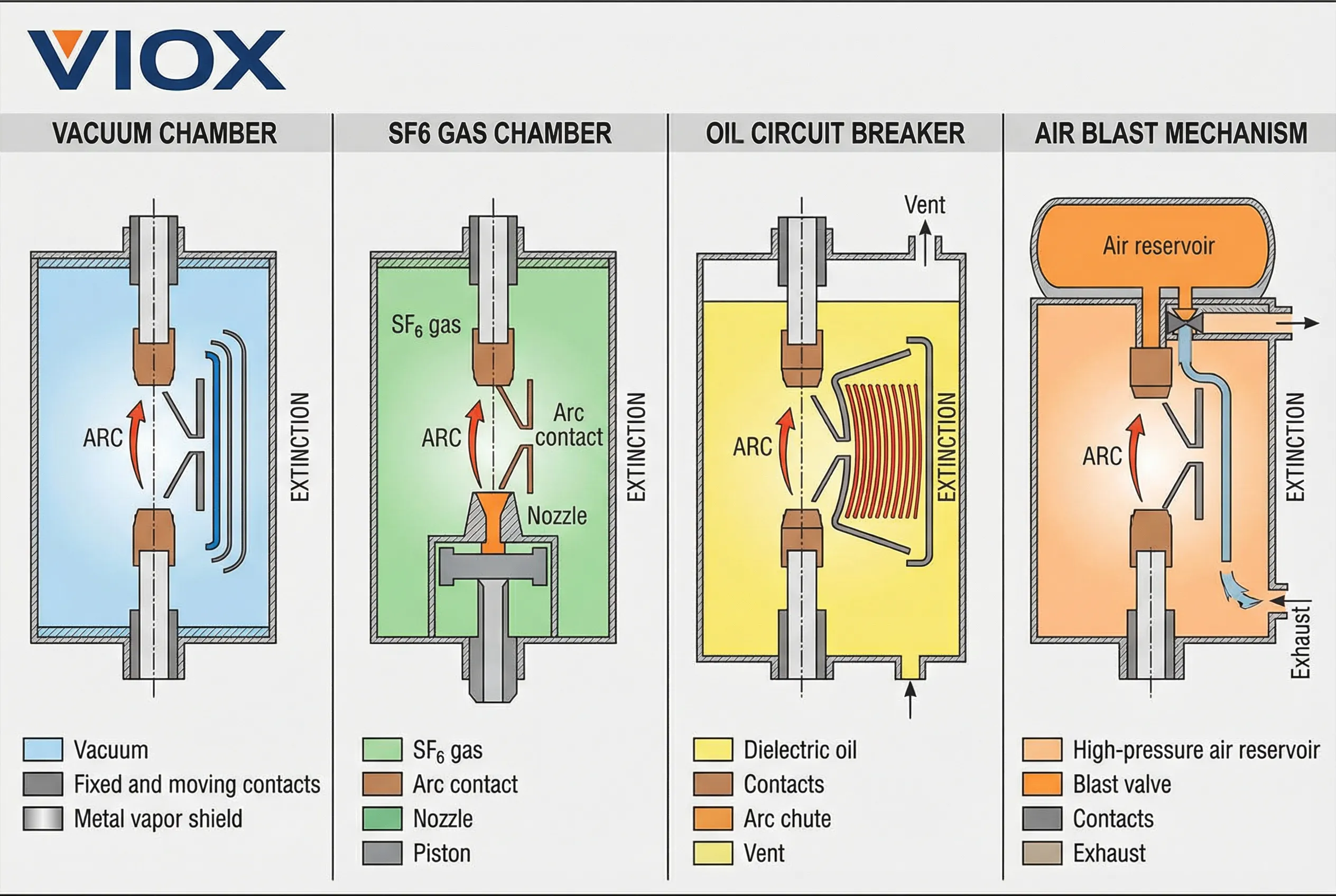
Circuit Breaker Types and Arc Extinction Methods
| ဆားကစ်အနိုင်အထက်အမျိုးအစား | Arc-Extinguishing Medium | Primary Extinction Mechanism | ပုံမှန် ဗို့အားအကွာအဝေး | အဓိက အားသာချက်များ | ကန့်သတ်ချက်များ |
|---|---|---|---|---|---|
| Vacuum Circuit Breaker (VCB) | High vacuum (10⁻⁴ to 10⁻⁷ Pa) | Rapid metal vapor diffusion and condensation | 3.6 kV to 40.5 kV | Minimal maintenance, compact design, no environmental concerns | Limited to medium voltage applications |
| SF₆ Circuit Breaker | Sulfur hexafluoride gas | Superior dielectric strength and thermal conductivity | 72.5 kV to 800 kV | Excellent interrupting capacity, reliable performance | Environmental concerns (greenhouse gas), gas monitoring required |
| Air Blast Circuit Breaker | Compressed air (20-30 bar) | High-velocity air blast cools and disperses arc | 132 kV to 400 kV | Proven technology, no toxic gases | Requires compressor infrastructure, noise generation |
| Oil Circuit Breaker | ဓာတ်သတ္တုဆီ | ဆီပြိုကွဲခြင်းမှ ဟိုက်ဒရိုဂျင်ဓာတ်ငွေ့ထွက်ရှိခြင်းသည် ပေါက်ကွဲမှုအာနိသင်ကို ဖြစ်စေသည်။ | ၁၁ ကေဗွီ မှ ၂၂၀ ကေဗွီ | ရိုးရှင်းသော တည်ဆောက်ပုံ၊ စျေးသက်သာသည်။ | မီးဘေးအန္တရာယ်၊ ပုံမှန်ဆီထိန်းသိမ်းမှု လိုအပ်သည်။ |
| လေအားလျှပ်စစ်ဆားကစ်ဘရိတ်ကာ | လေထု | သံလိုက်စက်ကွင်းသည် လျှပ်စစ်မီးပွားကို လမ်းကြောင်းလွှဲကာ မီးပွားလမ်းကြောင်းများထဲသို့ ဆွဲထုတ်သည်။ | ၁၅ ကေဗွီ အထိ | အထူးကြားခံပစ္စည်း မလိုအပ်ပါ၊ ရိုးရှင်းသော ပြုပြင်ထိန်းသိမ်းမှု | ကန့်သတ်ထားသော ဖြတ်တောက်နိုင်စွမ်း၊ ထုထည်ကြီးမားသော ဒီဇိုင်း |
နည်းပညာဆိုင်ရာ သတ်မှတ်ချက်များ- ဆားကစ်ဘရိတ်ကာများရှိ လျှပ်စစ်မီးပွား ကန့်သတ်ချက်များ
| ဇာတိ | ပုံမှန်တန်ဖိုးများ | အရေးပါမှု |
|---|---|---|
| လျှပ်စစ်မီးပွား အပူချိန် | ၁၅,၀၀၀°C မှ ၃၀,၀၀၀°C | ပစ္စည်းတိုက်စားနှုန်းနှင့် အအေးခံရန် လိုအပ်ချက်များကို ဆုံးဖြတ်သည်။ |
| လျှပ်စစ်မီးပွား ဗို့အား | 30V မှ 500V (အမျိုးအစားအလိုက် ကွဲပြားသည်) | စွမ်းအင်ပျံ့နှံ့မှုနှင့် TRV လက္ခဏာများကို ထိခိုက်စေသည်။ |
| အနည်းဆုံး လျှပ်စစ်မီးပွား အချိန် (50 Hz) | ၈-၂၀ မီလီစက္ကန့် | လုံလောက်သော ထိတွေ့မှု ခွဲထုတ်ခြင်းနှင့် အအေးခံရန် လိုအပ်သည်။ |
| ဒိုင်အီလက်ထရစ် ပြန်လည်ကောင်းမွန်နှုန်း | ၅-၂၀ ကေဗွီ/မိုက်ခရိုစက္ကန့် | မီးငြိမ်းပြီးနောက် လျှပ်ကာအား ပြန်လည်ရရှိမှု အရှိန် |
| TRV အထွတ်အထိပ် အချက် | ၁.၄ မှ ၁.၈ × စနစ်ဗို့အား | ပြန်လည်ကောင်းမွန်ချိန်အတွင်း အမြင့်ဆုံးဗို့အား ဖိအား |
| RRRV (မြင့်တက်နှုန်း) | ၀.၁-၅ ကေဗွီ/မိုက်ခရိုစက္ကန့် | ပြန်လည်ရိုက်ခတ်နိုင်ခြေကို ဆုံးဖြတ်သည်။ |
| ထိတွေ့မှု တိုက်စားနှုန်း | လုပ်ဆောင်မှု ၁၀၀၀ လျှင် ၀.၀၁-၁ မီလီမီတာ | ပြုပြင်ထိန်းသိမ်းမှု ကြားကာလများနှင့် ထိတွေ့မှု သက်တမ်းကို ထိခိုက်စေသည်။ |
မကြာခဏမေးမေးခွန်းများ
မေး- ဆားကစ်ဘရိတ်ကာများသည် ချိတ်ဆက်မှုပြတ်တောက်ချိန်အတွင်း လျှပ်စစ်မီးပွားများကို အဘယ်ကြောင့် လုံးဝမဖယ်ရှားနိုင်သနည်း။
အေ- အေစီ စနစ်များတွင်၊ ထိန်းချုပ်ထားသော လျှပ်စစ်မီးပွားများသည် လုံခြုံသော လျှပ်စီးကြောင်း ဖြတ်တောက်ရန်အတွက် မရှိမဖြစ်လိုအပ်ပါသည်။ လျှပ်စစ်မီးပွားများကို ဖယ်ရှားခြင်းသည် လှုံ့ဆော်မှုစွမ်းအင်ကို အန္တရာယ်ရှိသော ဗို့အားမြင့်များ ဖြစ်ပေါ်စေမည်ဖြစ်သည်။ လျှပ်စစ်မီးပွားသည် စွမ်းအင်ကို ဘေးကင်းစွာ ရင်းမြစ်သို့ ပြန်ပို့နိုင်စေမည့် စီမံခန့်ခွဲထားသော လျှပ်ကူးလမ်းကြောင်းကို ပေးစွမ်းပြီး လျှပ်စီးကြောင်းသည် သဘာဝအတိုင်း သုညသို့ရောက်သည်အထိ စက်ပစ္စည်းပျက်စီးခြင်းနှင့် စနစ်မတည်ငြိမ်ခြင်းတို့ကို ကာကွယ်ပေးသည်။.
မေး- ဆားကစ်ဘရိတ်ကာ လည်ပတ်မှုတွင် TRV နှင့် RRRV အကြား ကွာခြားချက်ကား အဘယ်နည်း။
အေ- TRV (ယာယီ ပြန်လည်ရရှိသော ဗို့အား) သည် လျှပ်စစ်မီးပွား ငြိမ်းပြီးနောက် ဘရိတ်ကာ ထိတွေ့မှုများတွင် ပေါ်လာသော စုစုပေါင်း တုန်ခါဗို့အားဖြစ်သည်။ RRRV (ပြန်လည်ရရှိသော ဗို့အား မြင့်တက်နှုန်း) သည် ဤဗို့အားသည် မူလတွင် မည်မျှလျင်မြန်စွာ မြင့်တက်လာသည်ကို တိုင်းတာပြီး ကေဗွီ/မိုက်ခရိုစက္ကန့်ဖြင့် ဖော်ပြသည်။ RRRV သည် အရေးကြီးသည်၊ အကြောင်းမှာ ဗို့အားသည် ဒိုင်အီလက်ထရစ်အား ပြန်လည်ကောင်းမွန်သည်ထက် ပိုမိုမြန်ဆန်စွာ မြင့်တက်ပါက လျှပ်စစ်မီးပွား ပြန်လည်ရိုက်ခတ်မှု ဖြစ်ပေါ်လာမည်ဖြစ်သည်။.
မေး- လေဟာနယ် ဆားကစ်ဘရိတ်ကာများသည် ဓာတ်ငွေ့ သို့မဟုတ် ဆီမပါဘဲ လျှပ်စစ်မီးပွားများကို မည်သို့ ငြှိမ်းသတ်သနည်း။
အေ- လေဟာနယ် ဆားကစ်ဘရိတ်ကာများသည် ထိတွေ့မှု တိုက်စားခြင်းမှ ထွက်လာသော သတ္တုအငွေ့ကို လျှပ်စစ်မီးပွားကြားခံအဖြစ် အသုံးပြုသည်။ မြင့်မားသော လေဟာနယ် (10⁻⁴ မှ 10⁻⁷ ပါစကယ်) တွင် သတ္တုအငွေ့သည် ထိတွေ့မျက်နှာပြင်များနှင့် အကာများပေါ်တွင် လျင်မြန်စွာ ပျံ့နှံ့ပြီး စုစည်းသည်။ လေဟာနယ် ပတ်ဝန်းကျင်သည် ကောင်းမွန်သော လျှပ်ကာ ပြန်လည်ကောင်းမွန်မှုကို (၂၀ ကေဗွီ/မိုက်ခရိုစက္ကန့်အထိ) ပေးစွမ်းနိုင်ပြီး ပထမဆုံး လျှပ်စီးကြောင်း သုညဖြတ်ကျော်မှုတွင် လျှပ်စစ်မီးပွား ငြိမ်းသတ်နိုင်စေသည်။.
မေး- ဆားကစ်ဘရိတ်ကာတွင် အနည်းဆုံး လျှပ်စစ်မီးပွား အချိန်ကို မည်သည့်အချက်များက ဆုံးဖြတ်သနည်း။
အေ- အနည်းဆုံး လျှပ်စစ်မီးပွား အချိန်သည် ထိတွေ့မှု ဖွင့်လှစ်နှုန်း၊ လိုအပ်သော ခွဲထုတ်အကွာအဝေး၊ လျှပ်စစ်မီးပွား ငြှိမ်းသတ်သည့် ကြားခံပစ္စည်း ဂုဏ်သတ္တိများနှင့် စနစ်ဗို့အားအဆင့်ပေါ်တွင် မူတည်သည်။ မလုံလောက်သော လျှပ်စစ်မီးပွား အချိန်သည် မလုံလောက်သော ထိတွေ့မှုကွာဟချက် သို့မဟုတ် မပြည့်စုံသော အအေးခံခြင်းကို ဖြစ်ပေါ်စေပြီး ပြန်လည်ရရှိသော ဗို့အားပေါ်လာသောအခါ ပြန်လည်ရိုက်ခတ်မှုကို ဖြစ်စေသည်။ သုံးဆင့်စနစ်များသည် တစ်ပြိုင်နက် စက်ပိုင်းဆိုင်ရာ လုပ်ဆောင်မှုအတွက် အဆင့်ထောင့် ကွာခြားချက်များကို ထည့်သွင်းစဉ်းစားရန် လိုအပ်သည်။.
မေး- ဗို့အားမြင့် ဆားကစ်ဘရိတ်ကာများသည် ပိုမိုရှုပ်ထွေးသော လျှပ်စစ်မီးပွား ငြှိမ်းသတ်နည်းများကို အဘယ်ကြောင့် လိုအပ်သနည်း။
အေ- ဗို့အားမြင့်လေလေ ပိုရှည်လေလေ၊ စွမ်းအင်ပိုမိုများပြားသော လျှပ်စစ်မီးပွားများသည် အိုင်းယွန်းပိုမိုများပြားလေလေဖြစ်သည်။ စွမ်းအင်သိပ်သည်းဆ တိုးလာခြင်းသည် အအေးခံစနစ်များ တိုးမြှင့်ခြင်း၊ ထိတွေ့မှု ခရီးပိုရှည်ခြင်းနှင့် သာလွန်ကောင်းမွန်သော လျှပ်စစ်မီးပွား ငြှိမ်းသတ်သည့် ကြားခံပစ္စည်းများ လိုအပ်သည်။ ဗို့အားမြင့် စနစ်များသည် ပိုမိုမြင့်မားသော TRV အကျယ်များနှင့် RRRV နှုန်းများကိုလည်း ထုတ်ပေးပြီး ကပ်ဆိုက်စွာ ပြန်လည်ရိုက်ခတ်မှု မအောင်မြင်ခြင်းကို ကာကွယ်ရန်အတွက် ပိုမိုမြန်ဆန်သော ဒိုင်အီလက်ထရစ် ပြန်လည်ကောင်းမွန်မှုနှင့် ပိုမိုခံနိုင်ရည်ရှိမှု လိုအပ်သည်။.
နိဂုံး- ဘေးကင်းသော ဆားကစ်ကာကွယ်မှု နောက်ကွယ်မှ သိပ္ပံပညာ
ဆားကစ်ဘရိတ်ကာ ချိတ်ဆက်မှုပြတ်တောက်ခြင်း၏ အဓိက လုပ်ငန်းစဉ်လေးခု—ထိတွေ့မှု ခွဲထုတ်ခြင်းနှင့် လျှပ်စစ်မီးပွား တည်ထောင်ခြင်း၊ လျှပ်စစ်မီးပွား ထိန်းသိမ်းခြင်းနှင့် စွမ်းအင်ပြန်ပို့ခြင်း၊ လျှပ်စီးကြောင်း သုညဖြတ်ကျော်ခြင်းနှင့် ငြိမ်းသတ်ခြင်းနှင့် TRV ခံနိုင်ရည်ရှိခြင်း—တို့ကို နားလည်ခြင်းသည် ထိန်းချုပ်ထားသော လျှပ်စစ်မီးပွားများသည် ဖယ်ရှားရန် ဒီဇိုင်းချို့ယွင်းချက်များထက် လျှပ်စစ်စနစ် ကာကွယ်မှုအတွက် အဘယ်ကြောင့် အခြေခံကျကြောင်း ဖော်ထုတ်ပြသသည်။.
VIOX Electric ၏ အဆင့်မြင့် ဆားကစ်ဘရိတ်ကာ ဒီဇိုင်းများသည် ခေတ်မီ လျှပ်စစ်မီးပွား စီမံခန့်ခွဲမှု နည်းပညာများ၊ အကောင်းဆုံး ထိတွေ့ပစ္စည်းများနှင့် တိကျစွာ အင်ဂျင်နီယာပြုလုပ်ထားသော လျှပ်စစ်မီးပွား အခန်းများကို ပေါင်းစပ်ထည့်သွင်းထားပြီး လည်ပတ်မှု အခြေအနေအားလုံးတွင် ယုံကြည်စိတ်ချရသော ကာကွယ်မှုကို သေချာစေပါသည်။ လျှပ်စစ်မီးပွား စွမ်းအင်ကို ထိရောက်စွာ စီမံခန့်ခွဲခြင်းနှင့် နိုင်ငံတကာ စံချိန်စံညွှန်းများအတွင်း TRV ကို ခံနိုင်ရည်ရှိခြင်းဖြင့် VIOX ဆားကစ်ဘရိတ်ကာများသည် ခေတ်မီ လျှပ်စစ်စနစ်များ လိုအပ်သော ဘေးကင်းမှု၊ ယုံကြည်စိတ်ချရမှုနှင့် သက်တမ်းကို ပေးစွမ်းပါသည်။.
နည်းပညာဆိုင်ရာ သတ်မှတ်ချက်များ၊ အသုံးပြုမှု လမ်းညွှန်မှု သို့မဟုတ် စိတ်ကြိုက် ဆားကစ်ဘရိတ်ကာ ဖြေရှင်းနည်းများအတွက်၊, သင်၏ သီးခြား ကာကွယ်မှု လိုအပ်ချက်များကို ဆွေးနွေးရန် VIOX Electric ၏ အင်ဂျင်နီယာအဖွဲ့ထံ ဆက်သွယ်ပါ။.
