
I fusibili ad alta capacità di rottura (HRC) sono dispositivi di protezione elettrica specializzati, progettati per interrompere in modo sicuro correnti di guasto estremamente elevate senza danneggiare le apparecchiature circostanti. A differenza dei fusibili standard, i fusibili HRC possono gestire correnti di guasto significativamente superiori alla loro normale corrente di funzionamento, rendendoli essenziali per i sistemi elettrici industriali in cui la concentrazione di potenza e la sicurezza sono aspetti critici.
Capire i fusibili HRC: le basi
Un Fusibile HRC è un tipo di fusibile a cartuccia che può sopportare in sicurezza correnti di cortocircuito per un periodo di tempo predeterminato. Se la condizione di guasto persiste oltre questo intervallo di tempo, il fusibile si brucia per proteggere il circuito. La caratteristica distintiva che distingue i fusibili HRC è la loro capacità di interruzione – la massima corrente di guasto che possono interrompere in sicurezza, in genere 1500 A o superiore.
Caratteristiche principali dei fusibili HRC
- Capacità di rottura: I fusibili HRC possono interrompere correnti di guasto molto più elevate rispetto ai fusibili standard. Ad esempio, mentre un fusibile in vetro M205 ha un potere di interruzione pari a 10 volte la sua corrente nominale, un fusibile HRC ceramico delle stesse dimensioni può interrompere in sicurezza 1500 A indipendentemente dal suo amperaggio.
- Caratteristiche tempo-corrente: I fusibili HRC presentano caratteristiche di tempo inverso: correnti di guasto più elevate comportano tempi di interruzione più rapidi, mentre correnti di guasto più basse consentono tempi di interruzione più lunghi.
- Affidabilità: Questi fusibili garantiscono prestazioni costanti e non si deteriorano con il tempo, assicurando una protezione affidabile per periodi prolungati.
Costruzione e materiali dei fusibili HRC
Componenti principali
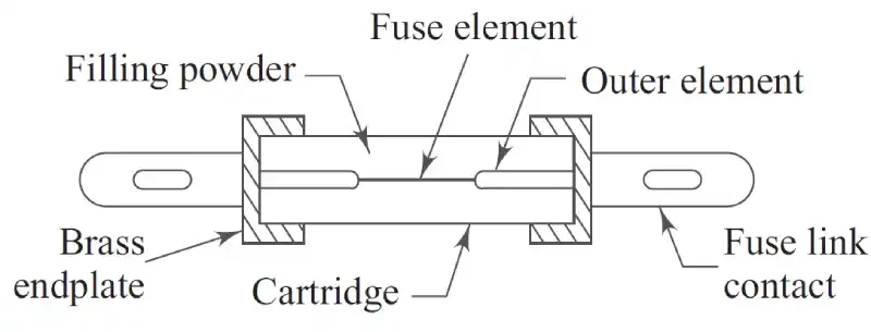
- Corpo in ceramica: L'involucro esterno è realizzato in ceramica o porcellana ad alta resistenza al calore, che offre un'eccellente resistenza meccanica e termica. Questa struttura in ceramica può resistere alle elevate pressioni sviluppate in caso di cortocircuito.
- Piastra terminale in ottone: I cappucci terminali in rame o ottone sono saldati saldamente a entrambe le estremità del corpo in ceramica mediante viti speciali progettate per resistere a condizioni di pressione estrema.
- Elemento fusibile: L'elemento che trasporta la corrente è in genere costituito da argento o rame Grazie alla sua bassa resistenza specifica e alle proprietà di fusione prevedibili, l'argento è preferito per la sua conduttività superiore e le prestazioni costanti.
- Giunti in stagno: L'elemento fusibile è dotato di giunti in stagno che collegano le diverse sezioni. Il punto di fusione dello stagno (240 °C) più basso rispetto all'argento (980 °C) impedisce al fusibile di raggiungere temperature pericolose in condizioni di sovraccarico.
- Polvere di riempimento: Lo spazio interno è riempito con materiali come quarzo, gesso di Parigi, polvere di marmo o gessoQuesto ripieno ha molteplici scopi:
- Assorbe il calore generato durante il funzionamento
- Previene il surriscaldamento del filo del fusibile
- Crea un'elevata resistenza elettrica quando reagisce con l'argento vaporizzato
- Aiuta a spegnere gli archi formati durante il funzionamento del fusibile
Come la costruzione consente un'elevata capacità di rottura
La combinazione di un corpo ceramico resistente al calore, di materiali di riempimento specializzati e di un design preciso dell'elemento fusibile consente ai fusibili HRC di interrompere in modo sicuro correnti di guasto molto più elevate rispetto ai fusibili convenzionali. La reazione chimica della polvere di riempimento con i vapori d'argento crea un percorso ad alta resistenza che estingue efficacemente l'arco.
Come funzionano i fusibili HRC: principio di funzionamento
Condizioni operative normali
In condizioni normali, la corrente scorre attraverso il fusibile HRC senza generare energia sufficiente a fondere l'elemento fusibile. Il fusibile funziona a temperature ben al di sotto del punto di fusione dei suoi componenti.
Condizioni di sovraccarico
Quando la corrente supera il valore nominale di 1,5 volte, il fusibile HRC può sopportare in sicurezza questa sovracorrente per 10-12 secondi. La polvere di riempimento assorbe il calore generato, impedendo il guasto immediato del fusibile e consentendo sovraccarichi temporanei.
Condizioni di cortocircuito
Durante i cortocircuiti, il processo avviene in diverse fasi:
- Riscaldamento dell'elemento: Una corrente eccessiva riscalda rapidamente l'elemento fusibile
- Fusione del ponte di stagno: I giunti di stagno si fondono prima a causa del loro punto di fusione più basso
- Formazione dell'arco: Un arco si stabilisce tra le estremità fuse dell'elemento fusibile
- Vaporizzazione degli elementi: L'elemento d'argento rimanente si fonde e vaporizza
- Reazione chimica: Il vapore d'argento reagisce con la polvere di riempimento, creando un'elevata resistenza elettrica
- Estinzione dell'arco: Il materiale ad alta resistenza aiuta a spegnere l'arco e ad interrompere il circuito
Tipi di fusibili HRC
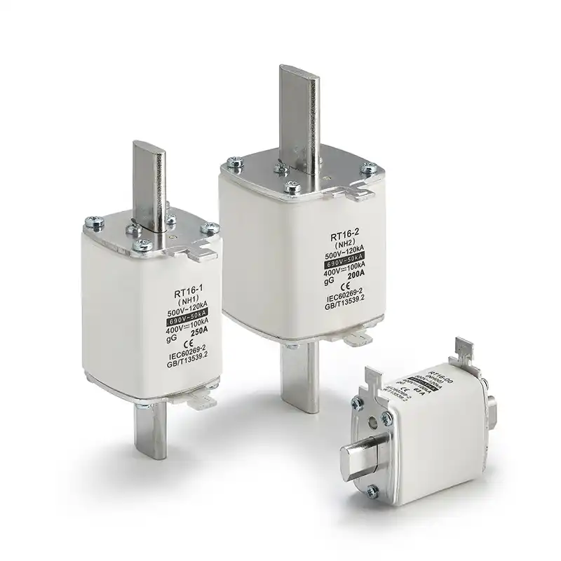
Fusibili HRC tipo NH
- Costruzione: Custodia rettangolare in ceramica con terminali a lama in metallo e piastra di copertura
- Applicazioni: Protezione del motore, sistemi fotovoltaici, sistemi di batterie e protezione per uso generale
- Tensione nominale: Tipicamente fino a 1140 V
- Gamma attuale: Fino a 1250A
- Caratteristiche:
- Indicatore di viaggio per mostrare lo stato del fusibile
- Alette di estrazione in metallo per una facile rimozione
- Disponibile in varie velocità di fusibile (semiconduttore, uso generale, azione lenta)
Fusibili HRC tipo DIN
- Applicazioni: Operazioni minerarie, apparecchiature di commutazione isolate a gas, protezione dei trasformatori e apparecchiature di commutazione isolate in aria
- Caratteristiche:
- Eccellenti prestazioni di cortocircuito
- Adatto a condizioni ambientali estreme
- Ampia gamma di correnti nominali
- Adattabile a diversi livelli di tensione
- Efficace sia per piccole sovracorrenti che per grandi cortocircuiti
Fusibili HRC a lama
- Costruzione: Corpo in plastica con tappi metallici predisposti per l'inserimento nella presa
- Applicazioni: Sistemi automobilistici, circuiti di controllo e sistemi elettrici leggeri
- Caratteristiche:
- Design leggero e compatto
- Facile installazione e sostituzione
- Disponibile con vari tipi di terminazione (saldatura, connessione rapida, crimpatura)
- Valori nominali correnti chiaramente contrassegnati per una facile identificazione
Vantaggi dei fusibili HRC
Vantaggi delle prestazioni superiori
- Elevata capacità di rottura: Può interrompere in modo sicuro correnti di guasto notevolmente più elevate rispetto ai fusibili convenzionali, garantendo una protezione superiore del circuito.
- Operazione rapida: Risposta estremamente rapida alle condizioni di guasto, interrompendo spesso i circuiti prima che venga raggiunto il picco di corrente di guasto.
- Design compatto: Una costruzione più efficiente consente dimensioni fisiche più ridotte rispetto ad altri dispositivi di protezione con valori nominali simili.
- Bassa energia passante: La rapidità di funzionamento riduce al minimo l'energia trasferita alle apparecchiature a valle in caso di condizioni di guasto.
- Economicamente vantaggioso: Costo iniziale inferiore rispetto ad altri dispositivi di interruzione del circuito con capacità di interruzione equivalente.
Affidabilità e manutenzione
- Nessuna manutenzione: Nessuna parte mobile o meccanismo complesso che richieda una manutenzione regolare.
- Prestazioni costanti: Funzionamento affidabile per tutta la loro durata di vita senza degrado delle prestazioni.
- Stabilità dell'età: Non si deteriorano nel tempo come altri dispositivi di protezione.
- Design semplice: Un minor numero di componenti significa una minore probabilità di guasto e una maggiore affidabilità.
Svantaggi e limiti
Limitazioni operative
- Natura monouso: Devono essere sostituiti dopo ogni operazione, a differenza degli interruttori ripristinabili.
- Generazione di calore: Il calore dell'arco elettrico durante il funzionamento può influire sui contatti elettrici e sugli interruttori nelle vicinanze.
- Requisiti di sostituzione: Richiede una scorta di fusibili di ricambio per diverse potenze e applicazioni.
- Surriscaldamento dei contatti: Può causare il surriscaldamento dei contatti adiacenti in caso di gravi condizioni di guasto.
Considerazioni sull'installazione
- Limitazioni di interblocco: Non può fornire funzionalità di interblocco come alcuni altri dispositivi di protezione.
- Sensibilità ambientale: Le prestazioni possono essere influenzate da condizioni ambientali estreme.
Applicazioni e usi
Applicazioni industriali
- Sistemi di distribuzione dell'energia: Protezione delle apparecchiature di commutazione e distribuzione ad alta tensione
- Protezione del motore: Protezione dei motori industriali da condizioni di sovraccarico e cortocircuito
- Protezione del trasformatore: Protezione primaria e di backup per trasformatori di potenza e distribuzione
- Operazioni minerarie: Protezione robusta per apparecchiature elettriche in ambienti minerari difficili
Applicazioni commerciali e di pubblica utilità
- Protezione dell'apparecchiatura di commutazione: Applicazioni di apparecchiature di commutazione isolate sia in aria che in gas
- Protezione dell'alimentatore: Sezionamento e protezione degli alimentatori elettrici
- Protezione di backup: Supporto di interruttori automatici e altri dispositivi di protezione primaria
- Energia solare e rinnovabile: Protezione per impianti fotovoltaici e applicazioni di accumulo di energia
Valori nominali e specifiche dei fusibili HRC
Corrente Nominale
Le correnti nominali standard dei fusibili HRC includono: 2, 4, 6, 10, 16, 25, 30, 50, 63, 80, 100, 125, 160, 200, 250, 320, 400, 500, 630, 800, 1000 e 1250 ampere.
Classificazioni di tensione
- Fusibili HRC a bassa tensione: Fino a 1000 V per applicazioni residenziali e commerciali
- Fusibili HRC ad alta tensione: Oltre 1000 V per applicazioni industriali e di pubblica utilità, estendendosi fino a oltre 40 kV
Standard di capacità di interruzione
La maggior parte dei fusibili HRC ha una capacità di interruzione nominale di 1500 A o superiore, e molti sono in grado di interrompere correnti superiori a 100 kA, a seconda della classe di tensione e dei requisiti dell'applicazione.
Criteri di selezione per i fusibili HRC
Fattori chiave da considerare
- Corrente nominale: Deve essere allineato con la normale corrente di funzionamento del circuito o dell'apparecchiatura protetta
- Capacità di rottura: Dovrebbe superare la massima corrente di guasto presunta nel sistema
- Tensione nominale: Deve essere compatibile con la tensione di esercizio del sistema
- Caratteristiche tempo-corrente: Dovrebbe corrispondere ai requisiti di protezione e coordinamento con altri dispositivi
- Dimensioni fisiche: Deve adattarsi allo spazio di montaggio disponibile e ai requisiti di connessione
- Condizioni ambientali: Considerare la temperatura, l'umidità e altri fattori ambientali
Confronto: fusibili HRC e altri dispositivi di protezione
Fusibili HRC vs fusibili a bassa capacità di interruzione (LBC)
| Funzione | Fusibili HRC | Fusibili LBC |
|---|---|---|
| Capacità di rottura | 1500A+ | 10x corrente nominale |
| Costruzione | Corpo in ceramica | Corpo in vetro |
| Materiale di riempimento | Polvere di quarzo/ceramica | Nessuno |
| Applicazioni | Industriale/Alta potenza | Bassa potenza/Residenziale |
| Costo | Più alto | Più basso |
| Affidabilità | Superiore | Adatto per bassa potenza |
Fusibili HRC vs interruttori automatici
Vantaggi dei fusibili HRC:
- Costo inferiore
- Nessuna manutenzione richiesta
- Operazione più veloce
- Installazione più semplice
Vantaggi di Interruttori automatici:
- Operazione ripristinabile
- Migliori capacità di controllo e monitoraggio
- Può fornire molteplici funzioni di protezione
Tendenze e sviluppi futuri
Progressi tecnologici
- Miglioramenti dei materiali: Sviluppo di materiali ceramici avanzati e composti di riempimento per prestazioni migliorate
- Integrazione intelligente: Integrazione con sistemi di monitoraggio per la manutenzione predittiva e la diagnostica di sistema
- Considerazioni ambientali: Sviluppo di materiali e metodi di smaltimento più rispettosi dell'ambiente
- Miniaturizzazione: Riduzione continua delle dimensioni mantenendo o migliorando la capacità di rottura
Conclusione
I fusibili HRC rappresentano un componente fondamentale nei moderni sistemi di protezione elettrica, offrendo una protezione affidabile ed economica contro le elevate correnti di guasto. La loro superiore capacità di interruzione, unita alla semplicità costruttiva e ai requisiti di manutenzione minimi, li rende ideali per applicazioni industriali e commerciali in cui una protezione affidabile dei circuiti è essenziale.
Comprendere la struttura, il funzionamento e l'applicazione dei fusibili HRC consente ai professionisti del settore elettrico di prendere decisioni consapevoli sulle strategie di protezione dei circuiti. Sebbene presentino limitazioni come il funzionamento monouso, i loro vantaggi nelle applicazioni ad alta potenza li rendono uno strumento indispensabile nella progettazione e manutenzione degli impianti elettrici.
Nella scelta dei fusibili HRC, un'attenta valutazione delle correnti nominali, della capacità di interruzione, dei requisiti di tensione e dei fattori specifici dell'applicazione garantisce una protezione ottimale e l'affidabilità del sistema.
Domande frequenti (FAQ) sui fusibili HRC
1. Qual è la differenza principale tra i fusibili HRC e LBC (bassa capacità di interruzione)?
La differenza principale risiede nella loro capacità di interruzione e costruzione:
- Fusibili HRC: Possono interrompere correnti di guasto di 1500 A o superiori, indipendentemente dalla corrente nominale. Sono realizzati in ceramica con polvere di riempimento per l'estinzione dell'arco.
- Fusibili LBC: Possono interrompere solo una corrente 10 volte superiore a quella nominale. Ad esempio, un fusibile LBC da 16 A può gestire una corrente di guasto fino a 160 A, mentre un fusibile HRC da 16 A può gestire oltre 1500 A.
Differenze di costruzione:
- I fusibili HRC utilizzano corpi ceramici con polvere di riempimento al quarzo
- I fusibili LBC in genere utilizzano corpi in vetro senza riempimento interno
- I fusibili HRC hanno una resistenza al calore e una resistenza meccanica superiori
2. Perché il mio fusibile HRC non salta in determinate condizioni di sovraccarico?
Questo è in realtà un caratteristica progettata di fusibili HRC. Possono trasportare in sicurezza 1,5 volte la loro corrente nominale per 10-12 secondi senza soffiare. Ciò è dovuto a:
- Assorbimento della polvere di riempimento: La polvere di quarzo interna assorbe il calore generato dalla sovracorrente
- Massa termica: La costruzione in ceramica e il materiale di riempimento impediscono l'aumento immediato della temperatura
- Tolleranza progettata: Ciò impedisce lo scatto indesiderato durante le normali correnti di avviamento o sovraccarichi temporanei
Se il sovraccarico persiste per oltre 10-12 secondi, il fusibile funzionerà normalmente.
3. I fusibili HRC possono essere riutilizzati dopo essere saltati?
No, i fusibili HRC sono dispositivi monouso e devono essere sostituiti dopo l'operazione. Questo perché:
- L'elemento fusibile viene completamente vaporizzato durante il funzionamento
- La polvere di riempimento interna reagisce chimicamente con il vapore d'argento
- Il corpo ceramico può sviluppare danni interni a causa dell'energia dell'arco
- Considerazioni sulla sicurezza: Il tentativo di riutilizzo potrebbe compromettere la protezione
Sostituire sempre con un fusibile dello stesso tipo e amperaggio HRC.
4. Quali materiali vengono utilizzati all'interno dei fusibili HRC e perché?
Materiali dell'elemento fusibile:
- Argento: Preferito per elevata conduttività e caratteristiche di fusione prevedibili
- Rame: Utilizzato in applicazioni a basso costo con buone prestazioni
- Giunti in stagno: Collegare le sezioni del fusibile con punto di fusione più basso (240°C contro 980°C per l'argento)
Materiali di riempimento:
- Polvere di quarzo: Mezzo primario di estinzione dell'arco
- Gesso di Parigi, polvere di marmo, gesso: Materiali di riempimento alternativi o supplementari
- Scopo: Assorbimento del calore, estinzione dell'arco e reazione chimica con argento vaporizzato
Materiali del corpo:
- Ceramica (steatite): Resistenza al calore e resistenza meccanica
- Terminali metallici: Rame o ottone per il collegamento elettrico
5. Come faccio a scegliere il fusibile HRC più adatto alla mia applicazione?
Seguire questi criteri di selezione chiave:
- Valutazione attuale: Scegliere un fusibile con una corrente nominale di 110-125% rispetto alla normale corrente di funzionamento
- Tensione nominale: Deve essere uguale o superiore alla tensione del sistema
- Capacità di rottura: Deve superare la massima corrente di guasto presunta
- Caratteristiche tempo-corrente: Soddisfare i requisiti di protezione
- Dimensioni fisiche: Garantire la compatibilità con i portafusibili esistenti
6. Qual è la differenza tra fusibili HRC e interruttori automatici?
| Funzione | Fusibili HRC | Interruttori automatici |
|---|---|---|
| Costo | Costo iniziale inferiore | Costo iniziale più elevato |
| Manutenzione | Nessuna manutenzione | Manutenzione regolare richiesta |
| Operazione | Monouso, deve essere sostituito | Ripristinabile, operazioni multiple |
| Velocità | Operazione più veloce | Funzionamento più lento |
| Indicazione | Potrebbe avere un indicatore di viaggio | Chiara indicazione di apertura/chiusura |
| Controllare | Nessun telecomando | Controllo remoto disponibile |
| Monitoraggio | Monitoraggio limitato | Capacità di monitoraggio avanzate |
| Selettività | Buono con un coordinamento adeguato | Ottime opzioni di selettività |
Scegli i fusibili HRC per: Applicazioni sensibili ai costi, requisiti di manutenzione minimi, protezione ad alta velocità
Scegli gli interruttori automatici per: Condizioni di guasto frequenti, esigenze di controllo remoto, requisiti di monitoraggio avanzati
7. Perché a volte i fusibili HRC non riescono a proteggere durante l'avviamento del motore?
Ciò può verificarsi a causa di selezione errata del fusibile:
- Cause comuni:
- Il fusibile sottodimensionato non può gestire la corrente di avviamento del motore
- Caratteristica tempo-corrente errata
- Carichi di inerzia elevati richiedono tempi di avviamento più lunghi
- Soluzioni:
- Utilizzo Fusibili con classificazione aM o gM progettato specificamente per la protezione del motore
- Controllare i valori I²t per garantire che la potenza nominale I²t del fusibile superi i requisiti energetici di avviamento del motore
8. Quali sono i problemi più comuni dei fusibili HRC?
Problemi operativi:
- Insuccesso prematuro: Sottodimensionato per l'applicazione, curva caratteristica errata
- Mancato funzionamento: Fusibile sovradimensionato, connessioni degradate
- Surriscaldamento dei contatti: Collegamenti scadenti, corrosione o cicli termici
- Problemi di coordinamento: Selettività impropria con dispositivi upstream/downstream
Problemi ambientali:
- L'ingresso di umidità può influire sulle prestazioni
- Le temperature estreme potrebbero richiedere un derating
- Le vibrazioni possono causare danni meccanici
9. Quanto durano in servizio i fusibili HRC?
Durata tipica del servizio: 15-20 anni in condizioni normali
Fattori che influenzano la durata della vita:
- Condizioni ambientali: temperatura, umidità, vibrazioni
- Modelli di carico: il carico elevato continuo riduce la durata
- Attività di guasto: ogni condizione di quasi guasto invecchia leggermente il fusibile
- Qualità della connessione: connessioni scadenti accelerano l'invecchiamento
10. I fusibili HRC possono essere utilizzati per applicazioni CC?
Sì, ma con considerazioni importanti:
Sfide specifiche di DC:
- Nessuna corrente naturale zero: gli archi DC non si estinguono naturalmente come quelli AC
- Maggiore energia dell'arco: richiede capacità di estinzione dell'arco migliorate
- Tensione nominale: la tensione nominale CC è in genere inferiore a quella CA per lo stesso fusibile
Applicazioni DC:
- Sistemi fotovoltaici: uso comune nelle scatole di combinazione CC
- Sistemi di batterie: protezione dell'accumulo di energia
- Azionamenti per motori CC: applicazioni industriali CC
- Ricarica EV: protezione CC ad alta tensione
Criteri di selezione per DC:
- Utilizzare fusibili specificatamente dimensionati per la tensione CC
- Controllare la capacità di interruzione della corrente continua (spesso diversa da quella della corrente alternata)
- Considerare i requisiti di estinzione dell'arco
- Seguire le linee guida per l'applicazione DC del produttore
11. Cosa succede se installo un fusibile HRC con una corrente nominale troppo elevata?
Conseguenze dei fusibili sovradimensionati:
- Guasto di protezione: potrebbe non proteggere cavi e apparecchiature da danni da sovraccarico
- Problemi di coordinamento: potrebbe non coordinarsi correttamente con i dispositivi di protezione a valle
- Violazioni del codice: potrebbe violare i codici elettrici che richiedono un'adeguata protezione da sovraccarico
Approccio corretto: Dimensionare sempre i fusibili in base ai requisiti dell'apparecchiatura protetta e non in base alla capacità massima di corrente di guasto.
12. Come faccio a sapere se il fusibile HRC è bruciato?
Indicatori visivi:
- Indicatore di scatto: molti fusibili HRC hanno un indicatore meccanico che mostra quando sono bruciati
- Ispezione della finestra: alcuni tipi di cartuccia consentono l'ispezione visiva dell'elemento
- Esame fisico: cercare rigonfiamenti, scolorimenti o danni
Test elettrici:
- Test di continuità: utilizzare il multimetro per verificare la continuità attraverso il fusibile
- Misurazione della tensione: verificare la tensione attraverso il fusibile bruciato
- Misurazione della corrente: il flusso di corrente zero indica un fusibile bruciato
Indicatori di sistema:
- L'apparecchiatura non funziona: perdita di potenza al circuito protetto
- Funzionamento parziale del sistema: perdita monofase nei sistemi trifase
- Allarmi di protezione: il monitoraggio del sistema potrebbe indicare un guasto del fusibile
Nota di sicurezza: Disattivare sempre l'alimentazione del sistema prima di rimuovere i fusibili per ispezione o prova.
Correlati
Fusibile CA vs fusibile CC: guida tecnica completa per una protezione elettrica sicura
Come funziona un portafusibile?
Qual è la differenza tra fusibile e interruttore automatico?
