Introduzione
Le guide DIN sono le strisce di metallo che formano la spina dorsale dei moderni quadri elettrici. Nonostante il loro aspetto semplice, la scelta della guida DIN giusta è una decisione di progettazione critica che influisce direttamente sull'affidabilità, la sicurezza e la funzionalità delle vostre installazioni elettriche. Che stiate progettando un sistema di controllo industriale, automatizzando un edificio o creando un quadro elettrico residenziale, questa guida completa vi fornirà le conoscenze necessarie per prendere decisioni informate sulla scelta della guida DIN.
Cosa sono le guide DIN e perché sono importanti?

Le guide DIN sono guide metalliche standardizzate utilizzate come piattaforme di montaggio per vari componenti elettrici, elettromeccanici ed elettronici all'interno di rack di apparecchiature, armadi di controllo e contenitori. Il termine "DIN" deriva da Deutsches Institut für Normung (Istituto tedesco per la standardizzazione) e riflette le origini del sistema in Germania alla fine degli anni Venti.
Lo scopo principale di una guida DIN è quello di fornire un supporto meccanico sicuro per i componenti; non è progettata principalmente come conduttore elettrico o barra collettrice, anche se può servire come collegamento di messa a terra del telaio in condizioni specifiche. Questa distinzione è importante, poiché l'ipotesi di una conduttività intrinseca può portare a una progettazione impropria del sistema e a potenziali rischi per la sicurezza.
Queste guide di montaggio standardizzate sono adatte a una vasta gamma di dispositivi, tra cui:
- Interruttori automatici
- Morsettiere
- Relè e contattori
- Controllori logici programmabili (PLC)
- Alimentatori
- Controllori del motore
- Moduli I/O remoti
- Trasformatori e apparecchiature di condizionamento dell'energia
- Metri e dispositivi di misura
- Condizionatori e convertitori di segnale
L'adozione globale dei sistemi a guida DIN è dovuta a diversi vantaggi:
- Standardizzazione e compatibilità: I protocolli di dimensionamento e montaggio universali garantiscono l'uniformità dimensionale tra i componenti di diversi produttori, creando interoperabilità e opzioni di mercato competitive.
- Efficienza: Il meccanismo di montaggio a scatto accelera notevolmente l'installazione e semplifica la manutenzione, consentendo al contempo configurazioni di componenti ad alta densità in alloggiamenti più piccoli.
- Organizzazione e sicurezza: Il layout strutturato favorisce l'organizzazione logica, migliorando l'accessibilità per l'installazione, la risoluzione dei problemi e la manutenzione.
- Flessibilità e scalabilità: I componenti possono essere facilmente aggiunti, rimossi o riposizionati in base all'evoluzione dei requisiti del sistema, senza una riprogettazione completa.
- Costo-efficacia: Oltre al costo relativamente basso dei binari stessi, il sistema riduce le dimensioni dell'armadio e i cablaggi necessari, con conseguente risparmio di materiale e manodopera.
Conoscere gli standard e le specifiche delle guide DIN
L'efficacia e l'interoperabilità dei sistemi di guide DIN dipendono interamente dalla standardizzazione. Questi standard assicurano che le rotaie e i componenti di diversi produttori lavorino insieme senza problemi.
Standard chiave
La norma fondamentale che regola le guide DIN è la IEC 60715 (rispecchiata da norme regionali come la EN 60715), che definisce le dimensioni e i requisiti funzionali dei tipi più comuni di guide DIN. Sebbene sia il riferimento principale per i progetti attuali, altri standard hanno storicamente definito profili specifici:
- EN 50022: guide Top Hat da 35 mm precedentemente specificate (ora ampiamente coperte da IEC/EN 60715)
- EN 50035: Binari di tipo G specificati
- EN 50045: rotaie Miniature Top Hat da 15 mm specificate
- EN 50023/EN 50024: Binari di sezione C specificati
Per i nuovi progetti, la prassi migliore è quella di fare riferimento al profilo specifico (ad esempio, TS35x7.5) e all'attuale standard prevalente (IEC/EN 60715).
Dimensioni e tolleranze comuni
Le dimensioni delle guide DIN sono universalmente specificate in unità metriche (millimetri). Le guide sono generalmente prodotte in lunghezze standard, generalmente 1 metro o 2 metri, che vengono poi tagliate in base alle dimensioni richieste per applicazioni specifiche.
Gli standard definiscono le dimensioni critiche (larghezza, altezza, forma del profilo) e le tolleranze per garantire un montaggio corretto e sicuro dei componenti. Per la guida Top Hat da 35 mm (TS35), ampiamente utilizzata, molti componenti si attengono a incrementi di larghezza basati su un modulo standard, in genere largo 18 mm. Un piccolo interruttore potrebbe occupare 1 modulo (18 mm), mentre un dispositivo più grande potrebbe essere largo 4 moduli (72 mm).
Tipi di guide DIN: Profili e loro applicazioni
Esistono diversi profili di guide DIN, ciascuno standardizzato e adatto a particolari applicazioni in base alle dimensioni, alla forma e ai requisiti di carico.
TS35 (Top Hat): Lo standard del settore
La guida TS35, comunemente nota come guida "Top Hat" per la sua sezione trasversale simmetrica a forma di cappello, è il tipo più diffuso nelle moderne installazioni elettriche e di controllo industriali.
Dimensioni: La larghezza standard è di 35 mm. Disponibile in due profondità standard:
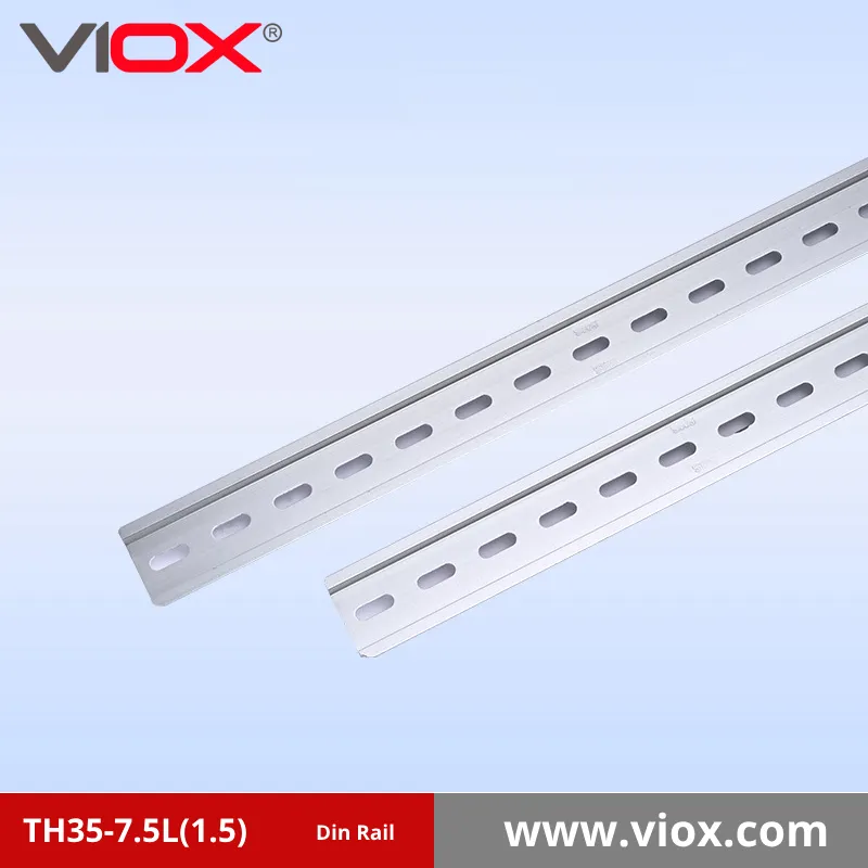
- 7,5 mm (standard): Designato IEC/EN 60715 - 35 × 7,5. Adatto alla maggior parte delle applicazioni generali.
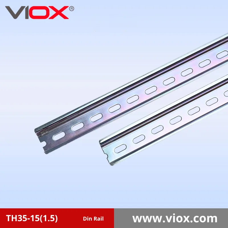
- 15 mm (cappello profondo): Designato IEC/EN 60715 - 35 × 15. Questo profilo più profondo offre maggiore resistenza e rigidità per il montaggio di componenti più pesanti o per coprire distanze maggiori tra i punti di montaggio.
Nomenclatura: Spesso indicato come TH35, TS35, o occasionalmente come Tipo O / Tipo Omega (Ω).
Applicazioni: La sua versatilità lo rende adatto al montaggio di una gamma estremamente ampia di dispositivi, tra cui interruttori, morsettiere, relè, PLC, alimentatori, controllori di motori, moduli I/O, contatori e altro ancora. Il profilo simmetrico facilita il montaggio e la rimozione dei componenti.
Data la sua ampia diffusione e la compatibilità con la maggior parte dei componenti montabili su DIN, la guida TS35 (con profondità di 7,5 o 15 mm) è in genere la scelta predefinita, a meno che non vi siano vincoli applicativi specifici.
TS15 (Cappello a cilindro in miniatura): Per le esigenze più compatte
La guida TS15 è essenzialmente una versione ridotta del profilo TS35 Top Hat.
Dimensioni: La larghezza standard è di 15 mm, con una profondità tipica di 5,5 mm.
Standard: Associato alla norma EN 50045.
Nomenclatura: Conosciuto anche come Miniature Top Hat o MR15.
Applicazioni: Le sue dimensioni compatte lo rendono ideale per le applicazioni in cui lo spazio è molto limitato, ad esempio all'interno di piccole scatole di controllo o di giunzione. Viene utilizzato per il montaggio di componenti più piccoli e leggeri, come morsettiere miniaturizzate, relè compatti o dispositivi speciali progettati appositamente per il formato della guida da 15 mm.
TS32 / Taglio cesareo: Eredità e usi specifici
La guida con sezione a C è caratterizzata da un profilo simmetrico a C.
Dimensioni: In genere, la larghezza è di 32 mm. Esistono anche altre larghezze, come 20 mm (C20).
Standard: Associato a norme come la EN 50024 (abrogata).
Applicazioni: Questo profilo è meno comune nei progetti contemporanei rispetto al TS35. Può capitare di trovarlo in installazioni più vecchie o di utilizzarlo per apparecchiature specifiche. Secondo alcune fonti, offre un buon supporto a parete per elementi come alimentatori o trasformatori. Il montaggio di componenti moderni progettati per guide Top Hat su guide a sezione C richiede spesso adattatori specifici.
Sezione G (G32): Per i componenti più pesanti
La rotaia con sezione a G si caratterizza per il suo profilo asimmetrico a forma di G.
Dimensioni: In genere 32 mm di larghezza.
Standard: Associato a EN 50035 (abrogato), BS 5825, DIN 46277-1.
Nomenclatura: Conosciuto anche come G-rail, TS32 o G32.
Montaggio: I componenti vengono generalmente montati agganciandoli al labbro più profondo (di solito posizionato in basso nel caso di montaggio a pannello) e poi ruotandoli per agganciarli al lato meno profondo. Il canale più profondo offre un maggiore supporto meccanico per i carichi più pesanti.
Applicazioni: Progettato specificamente per il montaggio di componenti più pesanti e di maggiore potenza, come alimentatori di grandi dimensioni, trasformatori, contattori pesanti o altri dispositivi sostanziali che richiedono un supporto robusto. La forma asimmetrica ha uno scopo funzionale che va oltre il supporto, in quanto aiuta a prevenire l'installazione errata dei componenti.
Altre/speciali rotaie
Mentre i tipi sopra descritti coprono la stragrande maggioranza delle applicazioni, esistono altri profili meno comuni per esigenze particolari. Ad esempio, le guide simmetriche per impieghi più gravosi, come un profilo di 75 mm di larghezza progettato per il montaggio di dispositivi eccezionalmente grandi e pesanti, come i componenti dei quadri elettrici. Inoltre, le varianti all'interno della famiglia delle sezioni C (C20, C30, C40, C50) rispondono a requisiti dimensionali specifici.
I materiali sono importanti: Scegliere la giusta composizione
Oltre alla forma e alle dimensioni del profilo, la composizione del materiale della guida DIN è un fattore critico di selezione, che influisce direttamente su resistenza, peso, resistenza alla corrosione e costo.
Scelta standard: acciaio (zincato/cromato)
Il materiale più comunemente utilizzato per la produzione di guide DIN è la lamiera di acciaio al carbonio laminata a freddo. Per proteggersi dalla corrosione negli ambienti industriali tipici, queste guide in acciaio sono quasi sempre trattate in superficie.
Finitura: La finitura standard prevede la placcatura elettrolitica con zinco, spesso seguita da un processo di passivazione al cromato (chiaro o giallo). Questo rivestimento offre una buona resistenza alla ruggine e alla corrosione nelle normali condizioni interne. Molti produttori specificano la conformità RoHS (Restriction of Hazardous Substances) per i loro processi di placcatura.
Vantaggi: L'acciaio zincato offre un eccellente equilibrio di proprietà per un uso generale. È robusto, durevole, resistente agli urti e alle vibrazioni e relativamente economico. L'economicità e la robustezza ne fanno la scelta obbligata per un'ampia gamma di quadri di controllo industriali e di armadi elettrici.
Limitazioni: Sebbene la placcatura offra una buona protezione, può essere compromessa da graffi o dall'esposizione prolungata all'umidità o a sostanze chimiche corrosive, permettendo all'acciaio sottostante di arrugginire.
Opzione leggera: Alluminio
L'alluminio è un'alternativa comune all'acciaio, che offre vantaggi distinti in alcuni scenari.
Vantaggi: Il vantaggio principale dell'alluminio è il suo peso notevolmente inferiore rispetto all'acciaio. Questo lo rende un'opzione interessante per le applicazioni in cui è fondamentale ridurre al minimo il peso complessivo, come ad esempio nei mezzi di trasporto o nelle installazioni mobili. L'alluminio possiede inoltre una resistenza intrinseca alla corrosione, grazie alla formazione di uno strato di ossido protettivo sulla sua superficie, che lo rende vantaggioso in ambienti moderatamente corrosivi.
Limitazioni: Il principale svantaggio dell'alluminio è la sua minore resistenza meccanica e rigidità rispetto all'acciaio. Potrebbe non essere adatto a sostenere componenti molto pesanti o in applicazioni con alti livelli di urti e vibrazioni, a meno che non sia adeguatamente dimensionato o supportato.
Opzione ad alte prestazioni: Acciaio inossidabile
Per le applicazioni che richiedono il massimo livello di durata e resistenza alla corrosione, l'acciaio inossidabile è il materiale preferito.
Vantaggi: L'acciaio inossidabile offre una resistenza superiore a un'ampia gamma di agenti corrosivi, tra cui umidità, sostanze chimiche e nebbia salina. Ciò lo rende essenziale per le installazioni in ambienti difficili o impegnativi come:
- Impianti di lavorazione degli alimenti e farmaceutici (a causa dei frequenti lavaggi e dei requisiti di igiene)
- Applicazioni marine (esposizione all'acqua salata)
- Contenitori per esterni (esposizione agli agenti atmosferici)
- Impianti chimici o altri ambienti industriali altamente corrosivi
Limitazioni: Lo svantaggio principale dell'acciaio inossidabile è il suo costo significativamente più elevato rispetto all'acciaio placcato e all'alluminio. Il suo utilizzo è in genere giustificato solo quando le condizioni ambientali o i requisiti di durata ne richiedono le proprietà superiori.
Binari pieni e binari scanalati/forati
Indipendentemente dal materiale, le guide DIN sono comunemente disponibili in due formati: solide o con perforazioni (fessure o fori rotondi) lungo la loro lunghezza.
Binari scanalati/forati:
- Vantaggi: Il vantaggio principale è la semplificazione del montaggio della guida stessa sulla piastra posteriore dell'involucro, poiché gli elementi di fissaggio possono essere inseriti direttamente attraverso le fessure. Ciò elimina la necessità di praticare fori di montaggio nella guida. Le perforazioni possono anche ridurre leggermente il peso e migliorare la circolazione dell'aria intorno ai componenti.
- Svantaggi: Le perforazioni riducono intrinsecamente la sezione trasversale complessiva della rotaia, il che può diminuire leggermente la resistenza e la rigidità massime rispetto a una rotaia piena.
Binari solidi:
- Vantaggi: Le guide piene offrono la massima integrità strutturale, resistenza e rigidità possibile per un determinato profilo e materiale. Ciò può essere vantaggioso in applicazioni che prevedono componenti molto pesanti o livelli significativi di urti e vibrazioni.
- Svantaggi: Il montaggio di guide solide richiede la foratura della guida stessa o l'utilizzo di morsetti o staffe di montaggio specifiche.
Criteri di selezione fondamentali: Abbinare il binario all'applicazione
La scelta della guida DIN ottimale comporta una valutazione sistematica dei requisiti e dei vincoli dell'applicazione specifica, trovando il miglior equilibrio tra più fattori.
Carico dei componenti (peso, dimensioni, densità)
Peso e dimensioni: Valutare il peso totale e le dimensioni fisiche dei dispositivi. I componenti più pesanti o più ingombranti, come gli alimentatori, i trasformatori o i contattori di grandi dimensioni, esercitano un maggiore stress meccanico sulla guida. Ciò potrebbe richiedere la scelta di un profilo più robusto, come la sezione G32 o la guida più profonda TS35x15 Top Hat, potenzialmente combinata con un materiale più resistente come l'acciaio.
Densità: Considerare il numero di componenti da montare per unità di lunghezza della guida. Le applicazioni ad alta densità di componenti beneficiano di profili efficienti dal punto di vista dello spazio, come il TS35 o, in casi estremi, il TS15. L'alta densità solleva anche problemi di dissipazione del calore. Sebbene le guide perforate possano offrire un vantaggio marginale grazie al miglioramento del flusso d'aria, la strategia principale di gestione termica si basa su un'adeguata spaziatura dei componenti, sulla ventilazione del contenitore o sul raffreddamento attivo.
Condizioni ambientali
TemperaturaMentre i materiali standard delle guide DIN si comportano bene negli intervalli di temperatura tipici dell'industria, le temperature estreme (alte o basse) possono potenzialmente influire sulle proprietà dei materiali o causare problemi di espansione differenziale tra la guida e i componenti montati o l'involucro.
Corrosione: Si tratta di un fattore critico. Il livello di esposizione a umidità, sostanze chimiche, nebbia salina o procedure di lavaggio determina il livello di resistenza alla corrosione richiesto. La scelta spazia dall'acciaio zincato standard per ambienti tranquilli, all'alluminio per condizioni moderate o sensibilità al peso, fino all'acciaio inossidabile per applicazioni difficili, corrosive o critiche dal punto di vista igienico.
Vibrazioni e urti: Le installazioni soggette a vibrazioni o urti meccanici significativi, comuni nei trasporti (ferroviari, marittimi), nelle apparecchiature mobili o in prossimità di macchinari pesanti, richiedono soluzioni di montaggio robuste. Ciò comporta la scelta di profili più robusti (ad esempio, TS35x15, G32), l'utilizzo di acciaio per le sue proprietà di resistenza e smorzamento e, potenzialmente, la preferenza di guide piene rispetto a quelle scanalate per ottenere la massima rigidità. In queste condizioni è essenziale un fissaggio sicuro dei componenti mediante morsetti di estremità appropriati.
Disponibilità di spazio e disposizione dei pannelli
Spazio disponibile: Valutare le dimensioni interne dell'armadio o del contenitore. In applicazioni con profondità o larghezza estremamente limitate, la guida Miniature TS15 può essere l'unica opzione possibile.
Layout del pannello: Pianificare la disposizione delle guide e dei componenti per ottimizzare i percorsi di cablaggio, garantire uno spazio adeguato per il raffreddamento e l'accessibilità e facilitare la manutenzione o l'espansione futura. Il posizionamento delle guide DIN è spesso associato a sistemi di gestione dei cavi, come i condotti scanalati. Considerate l'uso di guide rialzate o di staffe angolate, se necessario, per liberare i condotti di cablaggio o migliorare l'accesso ai terminali.
Requisiti per la messa a terra
Una decisione critica per la progettazione è se la guida DIN stessa sarà incorporata nello schema di messa a terra del sistema.
Percorso di terra: Se la guida è destinata a fungere da conduttore di terra di protezione (PE) o da collegamento a terra del telaio, il materiale della guida (in genere acciaio o potenzialmente alluminio, se adeguatamente preparato) deve fornire un percorso continuo a bassa impedenza verso il punto di terra principale.
Blocchi di messa a terra: È necessario utilizzare morsettiere di messa a terra specializzate, progettate per realizzare un collegamento elettrico affidabile con il corpo della guida. Il semplice affidamento alle clip di montaggio meccanico dei componenti standard è generalmente insufficiente e non sicuro ai fini della messa a terra.
Conformità: L'intero sistema di messa a terra deve essere conforme ai codici elettrici e agli standard di sicurezza applicabili.
Compatibilità con il materiale dell'involucro
Una considerazione spesso trascurata ma fondamentale è la compatibilità elettrochimica tra il materiale della guida DIN e quello della custodia.
Corrosione galvanica: Se si utilizza un involucro metallico (ad esempio, acciaio verniciato, acciaio inox, alluminio), il montaggio di una guida DIN di un metallo significativamente diverso può creare una cella galvanica in presenza di umidità. Ciò può portare a un'accelerazione della corrosione del metallo meno nobile. Per evitare che ciò accada, si raccomanda vivamente di utilizzare una guida DIN dello stesso metallo dell'involucro o di un metallo galvanicamente compatibile.
Involucri in policarbonato: Se l'involucro è realizzato in un materiale non metallico come il policarbonato, la corrosione galvanica non è un problema e qualsiasi materiale per guide DIN può essere utilizzato in modo sicuro da questo punto di vista.
Requisiti specifici del settore
I diversi settori industriali hanno spesso pratiche tipiche o requisiti specifici che influenzano la scelta della guida DIN:
- Automazione industriale/produzione: Utilizza comunemente guide in acciaio TS35 standard, puntando su un'elevata densità di componenti, affidabilità e facilità di manutenzione per PLC, azionamenti, I/O, ecc.
- Automazione degli edifici (HVAC, illuminazione, sicurezza): Utilizza spesso guide TS35 per controllori, relè e alimentatori. Il TS15 può essere utilizzato in scatole di controllo più piccole e distribuite.
- Energia/Utility (Distribuzione di energia, energie rinnovabili): Possono essere presenti componenti più pesanti, come grandi interruttori o inverter, che richiedono potenzialmente guide G32 o TS35x15. Le installazioni all'aperto (ad esempio, le scatole di combinatori solari) richiedono materiali resistenti alla corrosione come l'alluminio o l'acciaio inossidabile.
- Trasporto (ferroviario, navale, automobilistico): Privilegia un'elevata resistenza agli urti e alle vibrazioni, spesso richiedendo profili robusti (TS35x15, G32), materiali in acciaio, fissaggi sicuri e la conformità a standard industriali specifici (ad esempio, EN 50155).
- Industria alimentare/farmaceutica: Richiede guide in acciaio inox a causa dei severi standard igienici, dei frequenti lavaggi e della potenziale esposizione a detergenti corrosivi.

Migliori pratiche di installazione e accessori
Tecniche di installazione adeguate e l'uso di accessori appropriati sono essenziali per sfruttare appieno i vantaggi del sistema a guida DIN e garantire un pannello di controllo affidabile, sicuro e manutenibile.
Montaggio della guida
Fissaggio: La pratica standard prevede l'utilizzo di viti o altri dispositivi di fissaggio adeguati. Se la rotaia è scanalata, gli elementi di fissaggio passano direttamente attraverso le fessure preforate. Per le guide solide, è necessario praticare dei fori nella guida in punti appropriati. Il fissaggio deve essere sufficientemente sicuro da sostenere l'intero peso dei componenti montati e da resistere alle vibrazioni o agli urti previsti.
Taglio: Le guide sono spesso fornite in lunghezze standard di 1 o 2 m e devono essere tagliate per adattarsi alle dimensioni specifiche del pannello. Si consiglia di utilizzare strumenti specializzati per il taglio delle guide DIN, che consentono di ottenere tagli puliti e precisi a 90 gradi, senza sbavature o deformazioni. È possibile utilizzare seghetti o seghe elettriche, ma spesso lasciano bordi ruvidi che richiedono un'accurata sbavatura per garantire la sicurezza e il corretto montaggio dei componenti.
Orientamento: Le guide possono essere montate in orizzontale o in verticale. Per esigenze specifiche di layout o per migliorare l'accessibilità/visibilità, sono disponibili staffe di montaggio angolate (ad esempio, con un'inclinazione di 35°).
Montaggio dei componenti sulla guida
Meccanismo: La maggior parte dei dispositivi montabili su guida DIN è dotata di clip o piedini di montaggio integrati progettati per agganciarsi al profilo specifico della guida. L'installazione prevede in genere l'aggancio di un bordo del piedino di montaggio del componente a un labbro della guida, quindi la spinta o la rotazione del componente finché la clip sul lato opposto non si aggancia saldamente all'altro labbro della guida.
Facilità d'uso: Questo metodo "a scatto" consente di installare, rimuovere o riposizionare rapidamente i componenti senza l'ausilio di strumenti specializzati, velocizzando notevolmente le operazioni di montaggio e manutenzione.
Accessori essenziali
Diversi accessori sono comunemente utilizzati, e spesso indispensabili, per completare un'installazione su guida DIN robusta e affidabile:
Morsetti di estremità/ staffe/stop: Sono componenti critici, in particolare per le guide montate in verticale o in ambienti soggetti a vibrazioni. Vengono installati alle estremità di un gruppo di componenti (o a intervalli lungo una lunga fila) per impedire il movimento laterale o lo scorrimento lungo la guida.
Distanziatori/piastre di separazione: Vengono inseriti tra componenti adiacenti sulla guida. Hanno molteplici funzioni, tra cui quella di fornire una distanza elettrica obbligatoria tra dispositivi che operano a tensioni diverse, creare spazio per la dissipazione del calore o separare visivamente gruppi funzionali di componenti.
Tappi terminali: Questi semplici tappi di plastica vengono applicati alle estremità tagliate della guida DIN. Proteggono dai bordi metallici taglienti, migliorando la sicurezza durante l'installazione e la manutenzione, e offrono un aspetto più pulito e rifinito.
Piedini di montaggio/adattatori: Questi accessori consentono di installare su una guida standard dispositivi non progettati originariamente con clip di montaggio su guida DIN integrata. Ciò aumenta la versatilità del sistema, consentendo l'inserimento di una gamma più ampia di componenti.
Considerazioni sulla gestione dei cavi
Un pannello di controllo ben organizzato si basa su una gestione efficace sia dei componenti che del cablaggio. Le guide DIN e i sistemi di gestione dei cavi, in genere le canaline, sono tecnologie complementari spesso utilizzate insieme.
Sinergia: Le guide DIN forniscono una piattaforma di montaggio organizzata per i componenti, mentre le canaline, solitamente montate parallelamente alle guide, forniscono canali per instradare e contenere il cablaggio di interconnessione in modo ordinato. Questa combinazione consente di ottenere un cablaggio pulito, accessibile e facilmente rintracciabile, semplificando notevolmente la risoluzione dei problemi e le modifiche.
Interazione con il layout: Durante la pianificazione del layout è necessario tenere conto del posizionamento e dell'altezza della guida DIN rispetto ai condotti dei fili. È necessario prevedere uno spazio sufficiente per consentire ai cavi di uscire dai condotti e collegarsi ai terminali dei componenti. È possibile utilizzare profili di guida DIN rialzati o staffe di montaggio specifiche per elevare i componenti, fornendo maggiore spazio per il cablaggio sotto o accanto alla guida.
Etichettatura e identificazione
Nei pannelli di controllo complessi che contengono numerosi componenti montati su più guide DIN, un'etichettatura chiara e coerente è fondamentale per l'efficienza operativa e la sicurezza.
Importanza: Ogni componente (interruttore, relè, morsettiera, modulo PLC, ecc.) deve essere chiaramente etichettato secondo gli schemi di cablaggio del sistema. Ciò consente ai tecnici di identificare rapidamente i dispositivi durante la messa in servizio, la ricerca guasti o la manutenzione, riducendo gli errori e i tempi di fermo.
Metodi: Le etichette possono essere applicate direttamente sui componenti o collocate su superfici di marcatura dedicate, spesso presenti su accessori come morsetti o morsettiere.
Errori comuni da evitare nella scelta delle guide DIN
Anche i professionisti più esperti possono commettere errori nella scelta delle guide DIN. Ecco alcune trappole comuni da evitare:
- Supponendo che tutti i componenti siano compatibili: Non tutti i dispositivi funzionano con tutti i tipi di binari. Verificare sempre la compatibilità prima dell'acquisto.
- Ignorare i requisiti di carico: Il sovraccarico delle rotaie oltre la loro capacità può provocarne l'abbassamento o la rottura. Verificare sempre la portata massima indicata dal produttore e rispettarla.
- Trascurare i fattori ambientali: Le temperature estreme possono influire sul montaggio dei binari contraendoli o espandendoli. Installare i binari in un ambiente che rientri nell'intervallo suggerito dal produttore.
- Installazione non corretta: Un disallineamento dovuto a una cattiva installazione può causare un funzionamento insoddisfacente a causa delle vibrazioni, che possono danneggiare i componenti. Utilizzare strumenti adeguati e misure accurate.
- Selezione basata solo sul prezzo: Sebbene le considerazioni sul budget siano importanti, la scelta dell'opzione più economica può comportare problemi di compatibilità, durata ridotta o problemi di sicurezza.
- Non considerare l'espansione futura: Pianificate la potenziale crescita del sistema scegliendo binari in grado di accogliere componenti aggiuntivi o lasciando spazio per l'ampliamento.
- Trascurare i requisiti di manutenzione: Le guide possono allentarsi con il tempo e le vibrazioni possono danneggiare l'apparecchiatura. Ispezionare e mantenere regolarmente l'installazione.
- Incompatibilità dei materiali: La mancata considerazione della corrosione galvanica quando si utilizzano metalli diversi può portare a guasti prematuri. Quando si utilizzano involucri metallici, il materiale della guida deve corrispondere a quello dell'involucro.
Guida alla selezione delle guide DIN per applicazione
Le diverse applicazioni hanno requisiti specifici per le guide DIN. Ecco una guida rapida basata sugli scenari di utilizzo più comuni:
Sistemi di automazione industriale
- Tipo di guida consigliato: Guida Top Hat da 35 mm (profondità 7,5 o 15 mm)
- Materiale: Acciaio zincato o acciaio inox per ambienti difficili
- Considerazioni: Elevata capacità di carico, resistenza alle vibrazioni, possibilità di espansione
Quadri elettrici residenziali
- Tipo di guida consigliato: Guida Top Hat da 35 mm (profondità 7,5 mm)
- Materiale: Acciaio zincato standard
- Considerazioni: Efficienza dello spazio, compatibilità con gli standard, efficienza dei costi.
Apparecchiature per le telecomunicazioni
- Tipo di guida consigliato: Binario Top Hat da 35 mm o binario miniaturizzato da 15 mm
- Materiale: Alluminio o acciaio
- Considerazioni: Densità dei componenti, interferenza del segnale, dissipazione del calore
Applicazioni esterne o marine
- Tipo di guida consigliato: Guida Top Hat da 35 mm (profondità 7,5 o 15 mm)
- Materiale: Acciaio inox o alluminio
- Considerazioni: Resistenza alla corrosione, alle fluttuazioni di temperatura, protezione dall'umidità
Attrezzature industriali pesanti
- Tipo di guida consigliato: Binari con sezione a G o binari con sezione a C
- Materiale: Acciaio per impieghi gravosi con protezione anticorrosione
- Considerazioni: Massima capacità di carico, smorzamento delle vibrazioni, durata.
Manutenzione e buone pratiche
Per garantire la longevità e il corretto funzionamento della vostra installazione su guida DIN, seguite queste buone pratiche di manutenzione:
- Utilizzare un panno morbido e asciutto per pulire i binari e rimuovere regolarmente polvere o detriti per garantire prestazioni ottimali dei dispositivi montati.
- Ispezionare regolarmente le rotaie per verificare che non vi siano crepe o danni. Sostituirli immediatamente se si notano danni alle apparecchiature elettriche.
- Controllare regolarmente le guide per assicurarsi che siano correttamente collegate a terra, se utilizzate come parte del sistema di messa a terra.
- Assicurare una distanza adeguata tra i componenti per garantire la ventilazione e la facilità di manutenzione.
- Utilizzare viti e ferramenta di montaggio adeguate per evitare che la guida si sposti nel tempo.
- Implementare un sistema di etichettatura chiaro per i componenti montati sulla guida per facilitare la risoluzione dei problemi.
- Tenere un registro dei tipi di guida DIN, delle dimensioni e delle specifiche utilizzate in ogni installazione.
- In caso di dubbio, consultate o rivolgetevi a un professionista per assicurarvi che la scelta e l'installazione siano corrette.
Conclusione: Fare una scelta informata
La guida DIN, nonostante la sua apparente semplicità, è un elemento fondamentale dei moderni sistemi di controllo elettrici e industriali. La scelta della guida DIN giusta non è un compito banale, ma una decisione di progettazione critica che influenza l'efficienza, l'affidabilità, la sicurezza e l'economicità dell'intero sistema.
Correlati
Come determinare la qualità di una guida DIN
Guida DIN vs. montaggio tradizionale
I 5 motivi principali per cui le guide DIN sono essenziali nelle moderne installazioni elettriche
