Ezen az oldalon
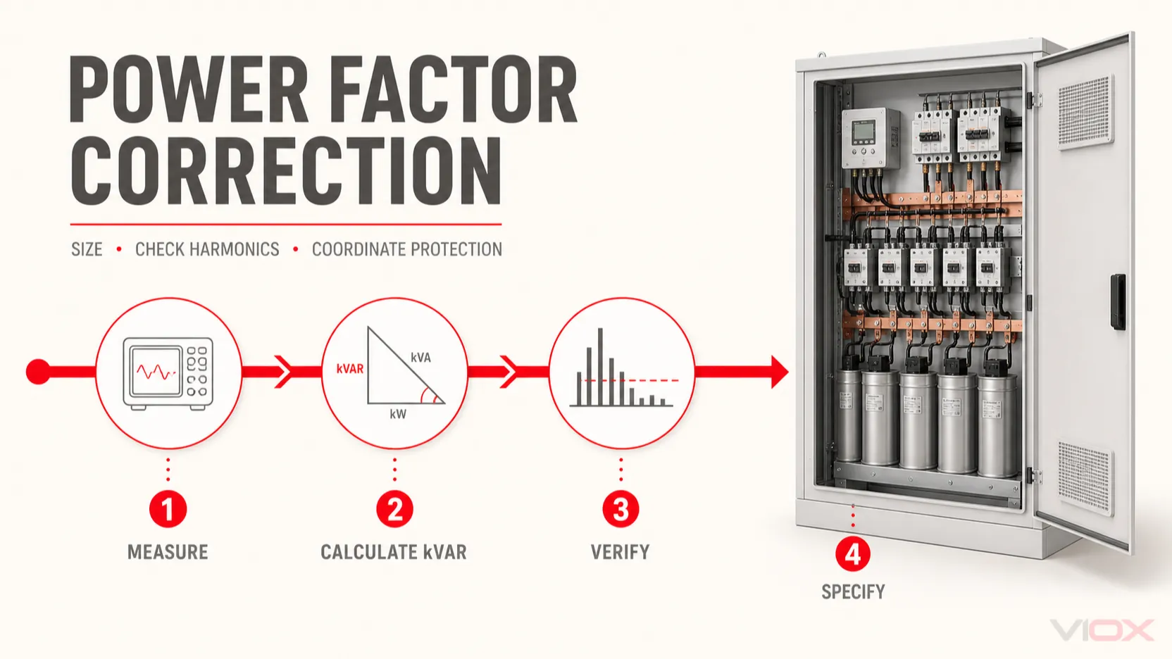
Egy kisfeszültségű teljesítménytényező-javító kondenzátortelep méretezéséhez, számítsa ki a mért teljesítménytényezőről a cél teljesítménytényezőre való elmozduláshoz szükséges meddőteljesítményt, majd ellenőrizze az eredményt a minimális terhelés, a harmonikus spektrum, a kapcsolási igénybevétel, a rendelkezésre álló rövidzárlati áram és a kapcsolószekrény hőmérsékleti határértékei alapján. A számítás elméleti kvar-igényt ad meg. Önmagában nem választ ki biztonságos kondenzátortelepet, mágneskapcsolót, fojtótekercset, biztosítót vagy megszakítót.
Az alapvető számítás a következő:
Qc = P x (tan phi1 - tan phi2)ahol:
Qca szükséges kapacitív meddőteljesítmény kvar-ban;Pa reprezentatív hatásos teljesítmény kW-ban;phi1a meglévő eltolási teljesítménytényezőnek megfelelő fázisszög;phi2a cél eltolási teljesítménytényezőnek megfelelő fázisszög.
A végleges kialakításnak a megadott működési tartományon belül enyhén induktív jellegűnek kell maradnia, kivéve, ha a közműszolgáltató vagy a rendszertanulmány ettől eltérő viselkedést ír elő. Ne törekedjen automatikusan 1,00-es teljesítménytényezőre, és ne telepítsen szabványos kondenzátortelepet harmonikusokban gazdag hálózatra a rezonancia kockázatának ellenőrzése nélkül.
Mérnöki döntések összefoglalása
- A szükséges kvar értéket a mért hatásos teljesítményből és az eltolási teljesítménytényezőből számítsa ki reprezentatív üzemi körülmények között, ne kizárólag a csatlakoztatott terhelés alapján.
- Ellenőrizze a minimális terhelésű és a generátoros üzemmódokat, hogy a fix vagy túlméretezett lépések ne vezessék a berendezést kapacitív teljesítménytényező tartományba.
- A szabványos kondenzátorok, fojtótekercsek, hangolt szűrők vagy aktív harmonikus szűrők kiválasztása előtt mérje fel a harmonikus viszonyokat; nincs olyan univerzális THD-százalék, amely minden projektre alkalmazható lenne.
- A kondenzátorokat, fojtótekercseket, kapcsolókészülékeket, védelmi eszközöket, vezetőket, kisütőegységeket és a szellőzést egy egységként hangolja össze.
- A számítást tekintse előzetes méretezésnek. A végső ellenőrzéshez a projekt szerinti zárlati áramadatokat, a gyártói alkalmazási táblázatokat és a vonatkozó IEC szerelési követelményeket kell használni.
Méretezéshez szükséges tervezési bemenetek
A megalapozott választás mért üzemi adatokon alapul, nem csupán a transzformátor kVA értékén, a csatlakoztatott motorok lóerő-teljesítményén vagy a közüzemi számlán megfigyelt legalacsonyabb teljesítménytényezőn.
| Bemenet | Miért fontos | Előnyben részesített bizonyítékok |
|---|---|---|
| Rendszerfeszültség, frekvencia, fázisok és földelési elrendezés | Meghatározza a kondenzátor csatlakoztatási, szigetelési, kapcsolási és védelmi követelményeit | Egyvonalas kapcsolási rajz és helyszíni mérés |
| Aktív teljesítményprofil kW-ban | Meghatározza a kompenzációt igénylő valós terhelést | Intervallummérő vagy teljesítményminőség-rögzítés egy reprezentatív cikluson keresztül |
| Meglévő eltolási teljesítménytényező | Az alapharmonikus kvar-számítás vezérlése | Eltolási PF jelentésére képes mérőműszer, ahol rendelkezésre áll |
| Valódi teljesítménytényező és harmonikus spektrum | Feltárja azt a torzítást, amelyet a kondenzátorok önmagukban esetleg nem korrigálnak | Energia-minőségelemző a tervezett csatlakozási ponton |
| Minimális, normál és maximális terhelés | Megakadályozza a túlkompenzációt kis terhelésű időszakokban | Naplózott terhelési profil, nem egy pillanatnyi érték |
| Célzott teljesítménytényező | Beállítja a korrekciós célt | Közüzemi tarifa, csatlakozási szerződés vagy projektkövetelmény |
| Nemlineáris terhelések jegyzéke | Jelzi a rezonancia és a harmonikus áram kockázatát | VFD-k, UPS rendszerek, egyenirányítók, hegesztőgépek, EV töltők és hasonló terhelések névleges értékei és működési mintázata |
| Transzformátor névleges teljesítménye és impedanciája | Befolyásolja a rövidzárlati szilárdságot és a hálózati rezonanciát | Transzformátor adattábla és vizsgálati adatok |
| Rendelkezésre álló rövidzárlati áram | Szükséges a védelmi eszközök és a szerelvények koordinációjához | Hibaelemzés vagy ellenőrzött tervezési érték |
| Telepítési feltételek | Befolyásolja a hűtést, a hézagokat, a tokozás védettségi fokozatát és az alkatrészek élettartamát | Környezeti hőmérséklet, tengerszint feletti magasság, szellőzés, szennyezettség és tokozási adatok |
Ha az olvasónak csak a terminológiára és a működési elvre van szüksége, használja a meglévőt APFC teljes alakja és kezelési útmutatója. Ez az oldal ott folytatódik, ahol az a definíció véget ér: a helyszíni adatok átalakítása előzetes banki specifikációvá.
Az eltolási teljesítménytényező nem mindig egyezik meg a valós teljesítménytényezővel
Közel szinuszos elektromos rendszer esetén a teljesítménytényezőt általában a következőképpen jelölik: cos phi, a feszültség és az áram közötti fázisszög koszinusza. A nemlineáris terheléseket ellátó hálózatokban az áramtorzítás további hatást fejt ki.
- Eltolási teljesítménytényező az alapharmonikus feszültség és az alapharmonikus áram közötti fáziskapcsolatot írja le.
- Valós teljesítménytényező a hatásos teljesítmény osztva a látszólagos teljesítménnyel, a teljes RMS hullámformák felhasználásával.
A söntkondenzátor alapfrekvenciás meddőteljesítményt szolgáltat, és javíthatja az eltolási teljesítménytényezőt. Nem szünteti meg az egyenirányítók, frekvenciaváltók, UPS-ek vagy kapcsolóüzemű tápegységek által keltett harmonikus áramokat. Ezért egy telephelyen javulhat az eltolási teljesítménytényező, miközben a valós teljesítménytényező a torzítás miatt korlátozott marad.
Ez a megkülönböztetés módosítja a tervezési döntést. Ha az alacsony teljesítménytényezőt főként induktív meddőteljesítmény okozza, akkor egy kondenzátortelep megfelelő lehet. Ha a torzítás a fő tényező, a projektnek fojtótekercsekre, hangolt szűrőre, aktív harmonikusszűrőre vagy a nemlineáris terhelések módosítására is szüksége lehet. A megoldásnak a mért hullámformákon és hálózati vizsgálaton kell alapulnia, nem pedig egyetlen összesített PF értéken.
A szükséges kondenzátortelep kvar értékének kiszámítása
1. lépés: Válassza ki a reprezentatív hatásos teljesítményt
Használja azt a hatásos teljesítményt, amely ahhoz az üzemállapothoz tartozik, amelyet a kompenzációs rendszernek ki kell szolgálnia. Egy folyamatosan terhelt motorhoz csatlakoztatott fix telep esetén a motor megadott üzemi adatai használhatók, a motor gyártójának korlátozásait figyelembe véve. Egy központi automatikus telep méretezését általában olyan terhelési profilra kell alapozni, amely tartalmazza a minimális, a normál és a csúcsüzemi időszakokat.
2. lépés: A teljesítménytényező átváltása meddőteljesítmény-tényezőkre
Minden egyes teljesítménytényezőhöz:
tan phi = sqrt(1 - PF^2) / PFEzután számítsa ki:
Qc = P x (tan phi1 - tan phi2)A képlet és a további elosztóberendezés-számítások szintén összefoglalva találhatók a VIOX-ban elektromos képletek kisfeszültségű elosztóberendezés tervezéséhez.
Számítsa ki a kondenzátortelep kvar értékét a VIOX eszközzel
Használja a VIOX teljesítménytényező-kalkulátor és kompenzációs eszköz az aktív teljesítmény, a meglévő teljesítménytényező, a cél teljesítménytényező, a feszültség és a fázisrendszer megadásához. Kiszámítja az előzetes kompenzációs igényt, valamint összehasonlítja a látszólagos teljesítményt és a vonali áramot a korrekció előtt és után.
A kalkulátor egy kiegyensúlyozott munkapontot modellez a teljesítményháromszög összefüggései alapján. A kvar eredménye nem tekinthető végleges telepspecifikációnak, mivel nem modellezi a terhelésváltozást, a gyakorlati kapcsolási lépéseket, a harmonikus rezonanciát, a kondenzátorok tűréseit, a védelmi eszközök koordinációját vagy az elosztóberendezés hőmérséklet-emelkedését. A berendezés kiválasztása előtt folytassa az alábbi ellenőrzésekkel.
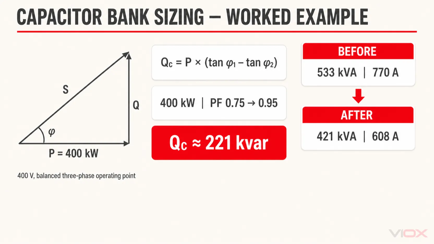
Kidolgozott példa: 400 kW, 0,75-ről 0,95 PF-re
Tegyünk fel egy kiegyensúlyozott háromfázisú terhelést a következőkkel:
- aktív teljesítmény:
P = 400 kW; - meglévő eltolási teljesítménytényező:
PF1 = 0.75 induktív; - cél eltolási teljesítménytényező:
PF2 = 0.95 induktív; - rendszerfeszültség:
400 V vonali feszültség; - a harmonikusokra való alkalmasság még nincs meghatározva.
tan phi1 = sqrt(1 - 0.75^2) / 0.75 = 0.882
tan phi2 = sqrt(1 - 0.95^2) / 0.95 = 0.329

Qc = 400 x (0.882 - 0.329)
Qc = 221 kvar körülbelül
Az elméleti igény tehát körülbelül 221 kvar a megadott munkaponton.
A látszólagos teljesítmény és a betápláló vonali áram szintén változik:
| Feltétel | Látszólagos teljesítmény | Hozzávetőleges vonali áram 400 V feszültségen |
|---|---|---|
| Korrektúra előtt, PF 0.75 | 400 / 0,75 = 533 kVA |
533 000 / (sqrt 3 x 400) = 770 A |
| Korrekció után a PF 0,95 | 400 / 0,95 = 421 kVA |
421 000 / (sqrt 3 x 400) = 608 A |
Ez a csökkenés a kompenzációs csatlakozási ponttól felfelé érvényes. Nem csökkenti a motor tekercsein belüli áramot, és nem szünteti meg a terhelésen belüli veszteségeket.
Ne konvertálja a 221 kvar értéket közvetlenül beszerzési megrendeléssé. A kiválasztott névleges banknak és fokozatainak illeszkedniük kell a terhelési profilhoz, a rendelkezésre álló szabványos névleges értékekhez, a feszültségtűréshez, a kondenzátortűréshez, a harmonikus terheléshez, a fojtótekercs kialakításához, a vezérlő viselkedéséhez, valamint a kapacitív teljesítménytényező kockázatához minimális terhelés mellett.
Válassza ki a korrekciós architektúrát
Az elhelyezés és a kapcsolási mód határozza meg, hogy az elektromos rendszer mely része részesül az áramtehermentesítés előnyeiben, és hogyan viselkedik a bank a terhelés változásakor.
| Architektúra | Legjobb megoldás | Fő tervezési határérték |
|---|---|---|
| Egyedi fix fázisjavítás | Egyetlen stabil induktív terhelés, amely hosszú ideig üzemel | Reteszelni kell a terheléssel, és a berendezés gyártója által megengedett kvar értéken belül kell maradnia |
| Csoportos fázisjavítás | Több terhelés, amelyek együtt indulnak és állnak le | A csoport üzemállapotának kiszámíthatónak kell lennie |
| Központi automatikus lépcsős fázisjavító berendezés | Változó létesítményterhelés többféle üzemelési kombinációval | A vezérlőt, az áramváltót (CT), a lépésfelbontást, a kapcsolási gyakoriságot, a harmonikusokat és a kis terhelés melletti viselkedést össze kell hangolni |
| Gyors tirisztoros kapcsolású fázisjavítás | Gyorsan ingadozó terhelések, ahol a mágneskapcsolós kapcsolás túl lassú vagy túlzott kopást okoz | Alkalmazásspecifikus termikus, félvezető, harmonikus és védelmi tervezést igényel |
A központi automatikus fázisjavítás gyakran praktikus, mivel a teljes lefelé irányuló terhelést kiszolgálja, és a karbantartást egy helyre összpontosítja. Nem távolítja el a meddő áramot a berendezéstől lefelé eső betápláló vezetékekből. Az egyedi fázisjavítás jobban tehermentesítheti a betápláló vezetéket, de szorosabb összehangolást igényel az egyes terhelésekkel.
Ellenőrizze a generátor és a transzformátor üzemmódjait
A közüzemi hálózati üzemre tervezett bank nem biztos, hogy megfelelő, ha a berendezés alacsonyabb rövidzárlati szilárdságú vagy eltérő meddőteljesítmény-képességű generátorra kapcsol át. Határozza meg, hogy a bankot blokkolni, korlátozni vagy eltérően kell-e vezérelni generátoros üzemmódban. Értékelje a kis terhelésű transzformátorokat is: a tartósan csatlakoztatott bank kapacitív meddőteljesítményt termelhet, ha a fő induktív terhelés hiányzik.
Válassza ki a lépésközt anélkül, hogy kapacitív teljesítménytényezőt hozna létre
Automatikus bank esetén a teljes kvar csak az egyik tervezési változó. A legkisebb lépés határozza meg a felbontást, míg a lépéssorrend szabályozza, hogy a bank milyen pontosan követi a terhelést.
Használja a rögzített meddőteljesítmény-profilt a következő négy kérdés megválaszolásához:
- Mi az az induktív kvarban mért legkisebb ismételhető változás, amelynek egy lépést kell kiváltania?
- Mi az a legalacsonyabb terhelés, amelynél a bank bekapcsolva marad?
- A legkisebb csatlakoztatott lépés létrehoz-e kapacitív teljesítménytényezőt minimális terhelésnél?
- Milyen gyakran kapcsol majd az egyes lépés egy normál termelési ciklus során?
Egy szemléltető 225 kvar-os bank egyenlő vagy egyenlőtlen lépésekre osztható, de a helyes sorrend nem választható ki kizárólag a teljes kvar alapján. A kisebb első lépés javítja a felbontást, de növeli a kapcsolókészülékek, a védelem, a vezetékezés, a hőtermelés, a költségek és a karbantartási pontok számát. A forgó lépéshasználatú vezérlő eloszthatja az üzemi terhelést, de a kapcsolási programjának meg kell egyeznie a fizikai lépésértékekkel.
A vezérlő válaszkésleltetése is számít. A rövid késleltetés a rövid terhelésváltozásokat követheti, és felgyorsíthatja az érintkezők kopását. A hosszú késleltetés a gyorsan változó terhelést korrigálatlanul hagyhatja. Az olyan terheléseknél, amelyek gyorsabban változnak, mint ahogy egy mágneskapcsolóval kapcsolt bank követni tudná, a vezérlő késleltetésének puszta csökkentése helyett fontolja meg statikus vagy hibrid rendszer alkalmazását.
A harmonikusok a helyes kvar-számítást is tönkretehetik a bankban
A tápláló hálózat induktivitása és a hozzáadott kapacitás rezonáns rendszert alkot. Ha annak sajátfrekvenciája a létesítményben jelen lévő valamelyik harmonikus közelében van, a feszültség és az áram felerősödhet. A következmények között szerepelhet a kondenzátor túlárama, kiolvadt biztosítékok, a mágneskapcsoló károsodása, a fojtótekercs túlmelegedése, zavaró kioldások vagy túlzott feszültségtorzítás.
Az IEC 61642 útmutatást nyújt a harmonikusokkal terhelt ipari AC hálózatokban alkalmazott szűrőkhöz és söntkondenzátorokhoz. Az ABB mérnöki útmutatója hasonlóképpen kifejti, hogy a soros fojtótekercs úgy választható ki, hogy a kondenzátor-fojtótekercs kombináció a legalacsonyabb jelentős harmonikus alatt legyen hangolva, csökkentve ezzel a hálózattal való rezonancia kockázatát.
Ne használjon egyetlen univerzális THD határértéket
Egy olyan kijelentés, mint “használjon fojtótekercseket 5% THD felett”, nem teljes kiválasztási szabály. A kockázat a következőktől függ:
- az egyes harmonikusok nagyságától és fázisviszonyaitól;
- a rendszer rövidzárlati szilárdsága és a transzformátor impedanciája;
- a kondenzátortelep kvar-értéke és a csatlakoztatott fokozatok száma;
- a nemlineáris terhelések és a telep elhelyezkedése;
- a hálózati topológia és a generátorüzem változásai;
- meglévő szűrők, kábelek és egyéb kondenzátorok.
Mérje meg a harmonikus spektrumot a tervezett csatlakozási ponton reprezentatív üzemi állapotok mellett. Egy valódi RMS-értéket mérő lakatfogó azonosíthatja a rendellenes kondenzátoráramot, de a harmonikus rendszám, a rezonanciakockázat és a megalapozott csökkentési terv meghatározásához teljesítményminőség-elemzőre és rendszertanulmányra van szükség.
A harmonikus választ válassza ki, ne csak a kondenzátor feszültségét
| Hálózati állapot | Előzetes irányelv | Ellenőrzés szükséges |
|---|---|---|
| Túlnyomórészt lineáris terhelések, alacsony mért torzítás, rezonanciaveszély nem azonosítható | Szabványos kondenzátortelep megfelelő lehet | Erősítse meg a kondenzátor, a kapcsolás, a védelem és az összeállítás névleges értékeit |
| Jelentős nemlineáris terhelés és rezonanciakockázat | Hangolt kondenzátor-fojtó telep | Harmonikus spektrum, hangolás, kondenzátor feszültségterhelés, fojtó hőteljesítmény és topológiai vizsgálat |
| Egy vagy több harmonikus rendszerszintű elnyelése szükséges | Hangolt passzív szűrő | Esettanulmány a szűrőről, beleértve az alkatrészek tűréseit és a hálózati változásokat |
| Széles vagy változó harmonikus spektrum, ahol a meddőteljesítmény-kompenzáció és a torzításvezérlés külön igény | Aktív vagy hibrid megoldás lehet megfelelő | Energiaminőség-vizsgálat, dinamikus követelmények és berendezések kompatibilitása |
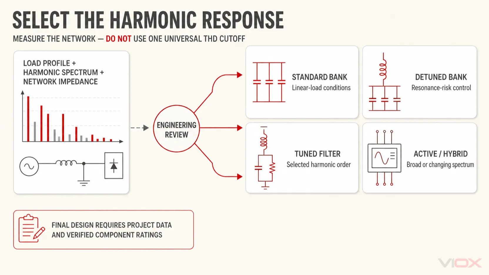
A a hangolt fojtótekercs nem automatikusan harmonikus szűrő. Elsődleges célja egy PFC-bankban általában az, hogy a soros rezonanciát a legalacsonyabb jelentős harmonikus alá tolja, és korlátozza az erősítést. A hangolt passzív szűrőt szándékosan úgy tervezték, hogy alacsony impedanciát biztosítson egy kiválasztott harmonikus rendszerszint körül. Ezeket a funkciókat nem szabad felcserélhető módon meghatározni.
A fojtótekercs beépítése a kondenzátoron eső alapfrekvenciás feszültséget is megemeli. A kondenzátor névleges feszültségét ezért össze kell hangolni a fojtótekercs hangolásával, a rendszerfeszültséggel, a tűrésekkel és a harmonikus viszonyokkal. A kondenzátor kiválasztása kizárólag a névleges gyűjtősín-feszültség alapján nem megfelelő egy hangolt (detuned) kompenzátorbank esetén.
Hangolja össze a teljes PFC-panelt
A névleges kondenzátoráram egy kiegyensúlyozott háromfázisú bank esetén:
Ic = 1000 x Qc / (sqrt 3 x U)A 225 kvar, 400 V-os példa esetében:
Ic = 1000 x 225 / (sqrt 3 x 400)
Ic = kb. 325 A
Ez egy névleges alapfrekvenciás áram, nem pedig megszakító, biztosíték, mágneskapcsoló, kábel vagy gyűjtősín névleges értéke. Az alkatrészek névleges értékeinek figyelembe kell venniük az alkalmazandó kondenzátortűréseket, a feszültségingadozást, a harmonikus áramot, a kapcsolási tranzienseket, a környezeti feltételeket, a csoportosítást, valamint a bevizsgált vagy ellenőrzött szerelési kialakítást.
Kondenzátorok és fojtótekercsek
Adja meg a kondenzátor szabványát, névleges feszültségét, névleges kvar értékét a tényleges üzemi feszültségen, a frekvenciát, a tűrést, a maximálisan megengedett áramerősséget, a kisütési elrendezést, a hőmérsékleti kategóriát és az élettartam végi biztonsági mechanizmust. Hangolt fojtótekercses telep esetén adja meg az illesztett kondenzátor-fojtótekercs kombinációt, a hangolási adatokat, a fojtótekercs veszteségeit, a hőosztályt, a hőmérséklet-védelmet és a szükséges szellőzést.
Kapcsolóeszközök
A kondenzátor feszültség alá helyezése nagyfrekvenciás bekapcsolási tranzienset hoz létre. Előfordulhat, hogy egy csak az állandósult állapotú áramerősség alapján kiválasztott általános célú mágneskapcsoló nem megfelelő. Adjon meg kondenzátorkapcsolásra alkalmas mágneskapcsolót vagy más, deklarált kondenzátorkapcsolási képességgel, megfelelő bekapcsolási áramkorlátozással, valamint a rövidzárlat elleni védelmi eszközzel való koordinációval rendelkező kapcsolóeszközt. Az IEC mágneskapcsolók AC-6b alkalmazási kategóriája a kondenzátortelepek kapcsolásához kapcsolódik; a VIOX mágneskapcsoló alkalmazási kategória útmutató elmagyarázza, miért fontos az alkalmazási kategória.
Ahol a terhelés gyors kapcsolást igényel, ellenőrizze, hogy indokolt-e a tirisztoros kapcsolás. A félvezető alapú kapcsolás megváltoztatja a hőtechnikai, szigetelési, hiba- és vezérlési kialakítást; ez nem csupán a mágneskapcsoló gyorsabb helyettesítése.
Rövidzárlat és túlterhelés elleni védelem
A védelmi rendszernek kezelnie kell a rendelkezésre álló hibaáramot, valamint a kondenzátortelep állandósult és tranziens viselkedését. Erősítse meg:
- várható rövidzárlati áram a bank csatlakozási pontján;
- védelmi eszköz megszakítási és bekapcsolási képessége;
- vezető és gyűjtősín hőkapacitása;
- kondenzátor és reaktor RMS árama a megadott harmonikus spektrum mellett;
- bekapcsolási áramlökés téves működés nélkül;
- koordináció az egyes lépésekkel és a bejövő bank eszközzel;
- leválasztási és biztonságos karbantartási követelmények;
- gyártói koordinációs táblázatok vagy igazolt szerelési bizonyítvány.
Ne alkalmazzon univerzális megszakító- vagy biztosítékszorzót anélkül, hogy ellenőrizné a kiválasztott kondenzátort, fojtótekercset, kapcsolókészüléket, védelmi karakterisztikát és az alkalmazandó szabványt. A VIOX külön termékforrásokat biztosít a MCCB-k és kisfeszültségű biztosítékok, de a végleges névleges értéket a mérnöki tervezésű kombinációból kell meghatározni, nem pedig egy általános blogbejegyzésben szereplő arányszámból.
Kisütés és tárolt energia vezérlése
A kondenzátorok a leválasztás után is veszélyes feszültséget tárolhatnak. Határozza meg a kisütőeszközöket, és ellenőrizze az alkalmazandó szabvány és projekt által megkövetelt maradékfeszültségre és kisütési időre vonatkozó teljesítményt. A kialakításnak meg kell akadályoznia az újbóli bekapcsolást is, mielőtt a maradékfeszültség a megengedett szintre csökkenne. A vezérlő késleltetése nem helyettesíti az ellenőrzött kisütési elrendezést.
Vezérlő és áramváltó (CT) elrendezése
Az automatikus vezérlőnek olyan feszültség- és áraminformációkra van szüksége, amelyek mind a terhelést, mind a kondenzátortelep hatását reprezentálják. Egy általános központi elrendezésben az áramváltót a terhelés és a telep csatlakozási pontja előtt (upstream) kell telepíteni, hogy a vezérlő lássa a hálózattal folytatott nettó meddőteljesítmény-cserét. A pontos elhelyezésnek, a fázis-hozzárendelésnek, az áttételnek, a polaritásnak és a vezérlő fázisreferenciájának követnie kell a gyártó kapcsolási rajzát.
A helytelen áramváltó-polaritás vagy fázis-hozzárendelés miatt a vezérlő kapacitást adhat hozzá akkor is, amikor el kellene távolítania azt. Tekintse át a mérési elveket a Áramváltók és feszültségváltók összehasonlítása dokumentumban, és az üzembe helyezés során ellenőrizze a vezérlő kijelzőjét egy ismert terhelési állapot mellett.
Szekrény és hőtechnikai kialakítás
A kondenzátorok, fojtótekercsek, mágneskapcsolók, védelmi eszközök, vezetők és gyűjtősínek mind hőt termelnek. A fojtótekercsek külön légáramlást vagy a hőmérsékletre érzékeny kondenzátoroktól való fizikai elválasztást igényelhetnek. A szekrény kialakításánál ellenőrizni kell a következőket:
- környezeti hőmérséklet és tengerszint feletti magasság;
- belső hőmérséklet-emelkedés és szellőzési útvonal;
- alkatrész-távolságok és a gyártói beépítési irányelvek;
- gyűjtősínek és vezetők áramterhelhetősége;
- átütési távolságok és kúszóáramutak;
- szekrény védettsége és szennyezettségi viszonyok;
- reaktortermosztát, szekrénytermosztát, ventilátorvezérlés és riasztási stratégia, ahol alkalmazzák;
- hozzáférés az ellenőrzéshez, a biztonságos kisütés ellenőrzéséhez és a cseréhez.
Szabványtérkép IEC-orientált specifikációhoz
| Standard | Vonatkozó hatókör ebben a tervezésben |
|---|---|
| IEC 61921 | Kisfeszültségű AC söntkondenzátor-telepek teljesítménytényező-javításhoz, beleértve a beépített kapcsoló- és vezérlőberendezéssel ellátott telepeket is |
| IEC 60831-1 | Self-healing shunt capacitor units and banks for AC systems up to and including 1,000 V; performance, rating, safety, installation, and operation |
| IEC 61642 | Passzív szűrők és söntkondenzátorok alkalmazása harmonikusokkal terhelt ipari AC hálózatokban |
| IEC 61439-1 és a vonatkozó berendezésrész | A teljes kisfeszültségű kapcsoló- és vezérlőberendezés-összeállítás ellenőrzése, ahol alkalmazható |
| IEC 60947 szabványsorozat | Vonatkozó kapcsoló-, vezérlő-, leválasztó- és védelmi eszközök a termékkörüknek megfelelően |
Egy IEC hivatkozással rendelkező alkatrész önmagában nem teszi megfelelõvé a kész elosztót. A berendezés gyártójának a teljes kialakítást ellenőriznie kell a vonatkozó összeszerelési szabvány és a deklarált üzemi feltételek szerint. A regionális közüzemi szabályok, a nemzeti szerelési kódexek és a projektspecifikációk további követelményeket írhatnak elő.
Üzembe helyezési sorrend
Az üzembe helyezésnek igazolnia kell a mérési láncot, a kapcsolási logikát, az elektromos választ és a termikus viselkedést, ahelyett, hogy csak azt mutatná be, hogy minden lépés lezárható.
- Feszültségmentesítse a panelt, ellenőrizze a feszültségmentességet, és vizsgálat előtt győződjön meg arról, hogy minden kondenzátor ki van sütve.
- Ellenőrizze az alkatrészek névleges értékeit, a vezetékkeresztmetszeteket, a nyomatékadatokat, a földelést, a hézagokat, a reaktor-kondenzátor illesztést és a védelmi eszközök koordinációját.
- Ellenőrizze a vezérlő feszültségreferenciáit, az áramváltó (CT) áttételét, az áramváltó polaritását, a fáziskiosztást, valamint a generátor vagy külső reteszeléseket.
- Helyezze feszültség alá a vezérlőáramkört, és az automatikus fokozatkapcsolás engedélyezése előtt ellenőrizze a riasztásokat és a hőmérséklet-bemeneteket.
- Kapcsolja be az egyes fokozatokat külön-külön, és ellenőrizze a fázisáramok, a kvar, a teljesítménytényező iránya és a vezérlő kijelzése várható változását.
- Ellenőrizze, hogy egyik fokozat sem okoz kapacitív teljesítménytényezőt a megadott minimális üzemi terhelés mellett.
- Mérje meg a kondenzátor- és reaktoráramokat valódi RMS-műszerekkel, és hasonlítsa össze azokat a megadott névleges értékekkel és a tervezési tanulmánnyal.
- Mérje meg a feszültség- és áramharmonikusokat reprezentatív nemlineáris terhelések működése mellett.
- Ellenőrizze a kapcsolási frekvenciát, a lépésforgatást, a kisütési/visszakapcsolási késleltetést, a szellőzést és a rendellenes hőmérsékletre vonatkozó riasztásokat.
- Végezzen terheléses termikus felülvizsgálatot, miután a rendszer elérte a stabil üzemi állapotot, és őrizze meg az alapértékeket a karbantartáshoz.
Bármilyen megmagyarázhatatlan túláram, gyors biztosítékműködés, mágneskapcsoló-zörgés, rendellenes reaktorzaj, túlmelegedés vagy a feszültségtorzítás növekedése vizsgálatot igényel az automatikus üzem folytatása előtt.
Kondenzátortelep ajánlatkérési ellenőrzőlista
Adja meg a szállítónak vagy a kapcsolószekrény-gyártónak a következő információkat:
- rendszerfeszültség, frekvencia, fázisok, földelési elrendezés és csatlakozási pont;
- minimális, normál és maximális kW/kvar terhelési profil;
- meglévő és célzott eltolási és valós teljesítménytényező;
- harmonikus spektrum és mérési pont;
- nemlineáris terhelések jegyzéke és üzemeltetési ütemterv;
- transzformátor kVA, impedancia és generátor üzemmódok;
- rendelkezésre álló rövidzárlati áram és a szükséges szerelvény rövidzárlati szilárdsága;
- számított kompenzációs kvar és az előnyben részesített fix/automatikus/gyors architektúra;
- szükséges lépésfelbontás és várható kapcsolási frekvencia;
- szabványos, fojtott, hangolt szűrős, aktív vagy hibrid kialakításra vonatkozó döntés;
- kondenzátor- és reaktornévleges értékek, hangolási adatok és hővédelem;
- kapcsolókészülék-üzemmód és rövidzárlati koordináció igazolása;
- betáp- és lépcsővédelem, leválasztás, valamint kisütési követelmények;
- vezérlőfunkciók, áramváltó (CT) részletek, kommunikáció, riasztások és reteszelések;
- burkolat IP-védettsége, környezeti hőmérséklet, tengerszint feletti magasság, szellőzés, kábelbevezetés és rendelkezésre álló hely;
- vonatkozó IEC szabványok, nemzeti szabályok, dokumentáció, rutinellenőrzés és üzembe helyezési jegyzőkönyvek.
A kiválasztás támogatásához adja meg a VIOX részére a rendszerszintű feszültséget, a mért terhelési profilt, a meglévő és a célzott PF-értéket, a harmonikusokról szóló jelentést, a transzformátor adatait, a hibaáram szintjét, a lépcsőkövetelményeket és a burkolati feltételeket. Ezek az adatok szükségesek a mágneskapcsolók, a megszakítók, az elosztóelemek és a kapcsolószekrény hardverének koordinálása előtt.
Gyakran Ismételt Kérdések
Méretezni kell-e a kondenzátortelepet 1,00-ás teljesítménytényező eléréséhez?
Alapértelmezés szerint nem. A terhelés és a mérés ingadozása az egységnyi célkitűzést kapacitív teljesítménytényezőbe fordíthatja át könnyebb üzemelés során. Használja a közüzemi vagy projektcélokat, és tartson fenn megfelelő induktív tartalékot, hacsak a rendszertanulmány másként nem rendelkezik.
Képesek a kondenzátorok a harmonikus teljesítménytényező javítására?
A kondenzátorok az alapfrekvenciás meddőteljesítményt javítják. Nem szüntetik meg a nemlineáris terhelésekből származó harmonikus áramot. Ezért a valódi teljesítménytényező a javítás után is a fázistolási teljesítménytényező alatt maradhat.
Mikor jobb egy automatikus kondenzátortelep, mint egy fix telep?
Az automatikus fokozatkapcsolású telep általában akkor megfelelőbb, ha az induktív kvar-igény jelentősen változik az üzemciklus során. A fix telep csak akkor megfelelő, ha a kompenzált terhelés és annak üzemi állapota kellően stabil, és a telep az adott terhelés nélkül nem maradhat csatlakoztatva.
Eltávolítja-e a harmonikusokat a hangolt fojtótekercs?
Nem feltétlenül. A PFC-telepekben a hangolt fojtótekercset általában arra használják, hogy a kondenzátor-fojtótekercs rezonanciáját a legalacsonyabb jelentős harmonikus alá tolják, és csökkentsék az erősítés kockázatát. A hangolt passzív szűrőt szándékosan egy kiválasztott harmonikus rend köré tervezik.
Hová kell telepíteni az APFC-vezérlő áramváltóját (CT)?
Az elhelyezésének lehetővé kell tennie, hogy a vezérlő mérni tudja a nettó terhelést és a kondenzátortelep hatását. Általános központi elrendezésben ez azt jelenti, hogy mind a terhelés, mind a telep elé (upstream) kell helyezni, de a pontos fázisnak, polaritásnak és vezetékezésnek követnie kell a vezérlő gyártójának kapcsolási rajzát.
Források és szabványok
- IEC 61921:2017 – Teljesítménykondenzátorok: Kisfeszültségű fázisjavító berendezések
- IEC 60831-1:2014 – Self-healing shunt power capacitors up to 1,000 V
- IEC 61642:1997 – Harmonikusokkal terhelt ipari AC hálózatok
- ABB – Fázisjavítás és harmonikusszűrés elektromos rendszerekben
- Eaton – Fázisjavítás: Útmutató üzemi mérnököknek
- Schneider Electric – Útmutató kisfeszültségű fázisjavító szekrények tervezéséhez és gyártásához