
在选型时 塑壳断路器(MCCB) 用于工业或商业设施时,您会遇到两种基本的触头设计方式:单断点与双断点结构。这种区别不仅是技术术语——它影响着断路器的故障电流分断方式、制约着分断能力等级,并决定了每种设计最适合的应用场景。.
两种技术均符合IEC 60947-2标准,在正确选型时均可提供可靠的保护。问题不在于哪种设计是普遍“更优”的,而在于哪种更适合您特定的故障电流状况、电压等级及保护要求。双断点MCCB在需要强效限流的高故障电流环境中表现卓越;单断点设计则在较低故障电流应用中可能具备成本优势且性能稳定。.
本指南将解析单断点与双断点MCCB之间的机械结构差异、电弧分断原理及性能权衡。您将了解每种技术的工作原理、IEC 60947-2测试数据所揭示的性能特点,以及如何为您的设施选择正确的结构配置。.
理解触头配置
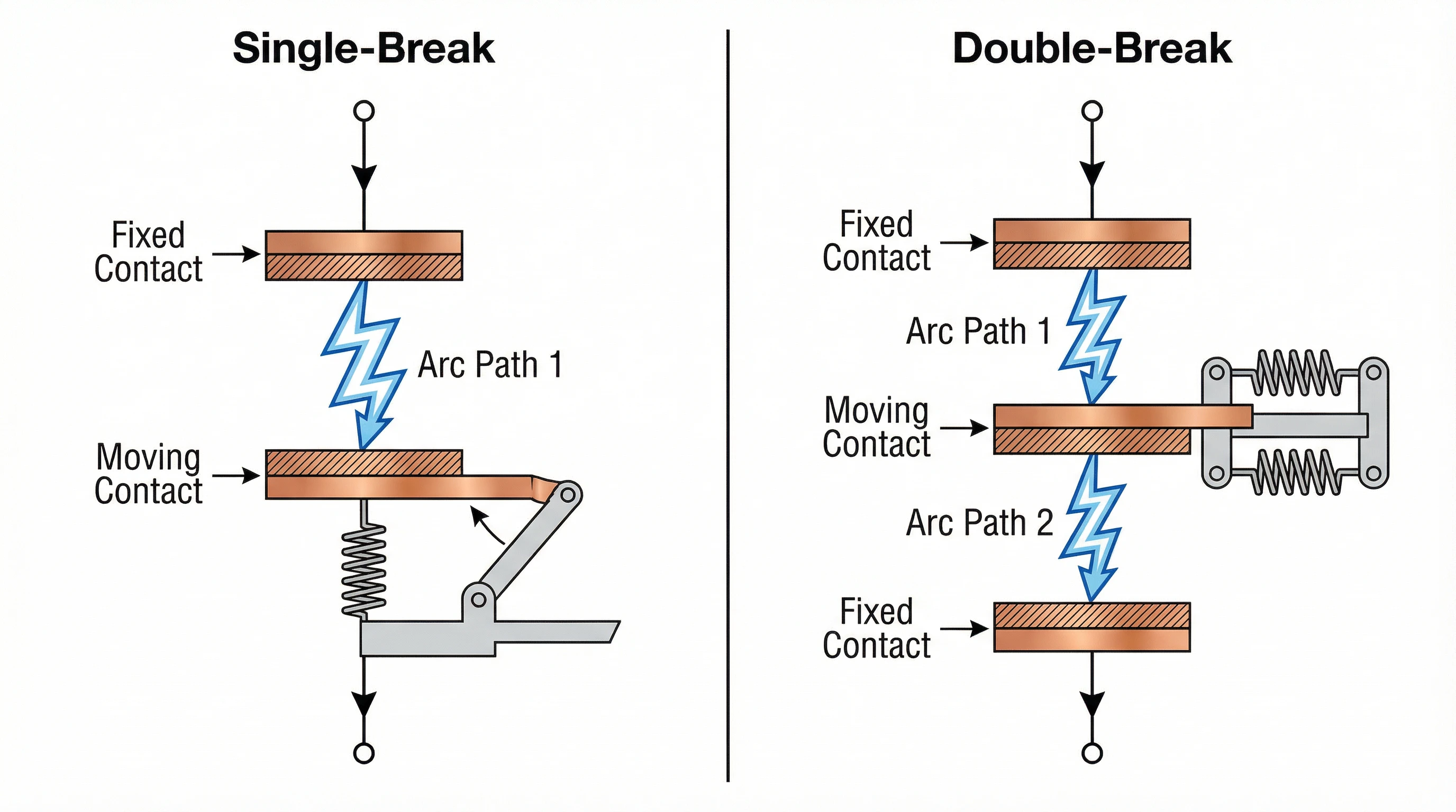
“单断点”与“双断点”描述了MCCB分断时每极存在的分断点数量。这种机械结构上的差异从根本上决定了电弧特性、电压发展过程及分断性能。.
单断点设计
在单断点结构中,每极具有一对触头——一个静触头,一个动触头。当故障发生且脱扣机构动作时,动触头与静触头分离,形成单一电弧路径。电流流经该分断点直至电弧在灭弧室中被熄灭。.
机械特性:
- 每极一个动触头
- 每极一个静触头
- 每极一个灭弧室
- 触头组件更简单,运动部件更少
- 电弧能量集中于单个灭弧室
单断点塑壳断路器依靠坚固的电弧室设计——包括分割板、磁吹线圈和电弧室几何结构——来快速熄灭电弧。全部电弧电压必须在该单一间隙上建立。.
双断点设计
双断点配置每极采用两组触头。通常,一个中央动触头与两个静触头(一上一下)分离,形成两个串联的电弧路径。当断路器脱扣时,电流必须同时流经两个分断点。.
机械特性:
- 每极一个中央动触头
- 每极两个静触头(或采用多个动/静触头组合的变体)
- 每极两个电弧室(或一个共享室处理两个电弧)
- 更复杂的触头组件和电弧管理
- 电弧能量在两个分断点之间分配
由于两个电弧串联发展,总电弧电压是两个间隙电压之和。这种更高的电弧电压可驱动更快的限流,但也会增加电弧室的机械应力,并需要精心的电弧室设计来管理压力和材料侵蚀。.
电弧分断原理
当塑壳断路器在故障条件下断开时,触头分离并形成电弧——一个等离子体通道,在空气间隙中传导故障电流。分断该电弧是断路器的主要任务。单断点与双断点设计处理此过程的方式存在显著差异。.
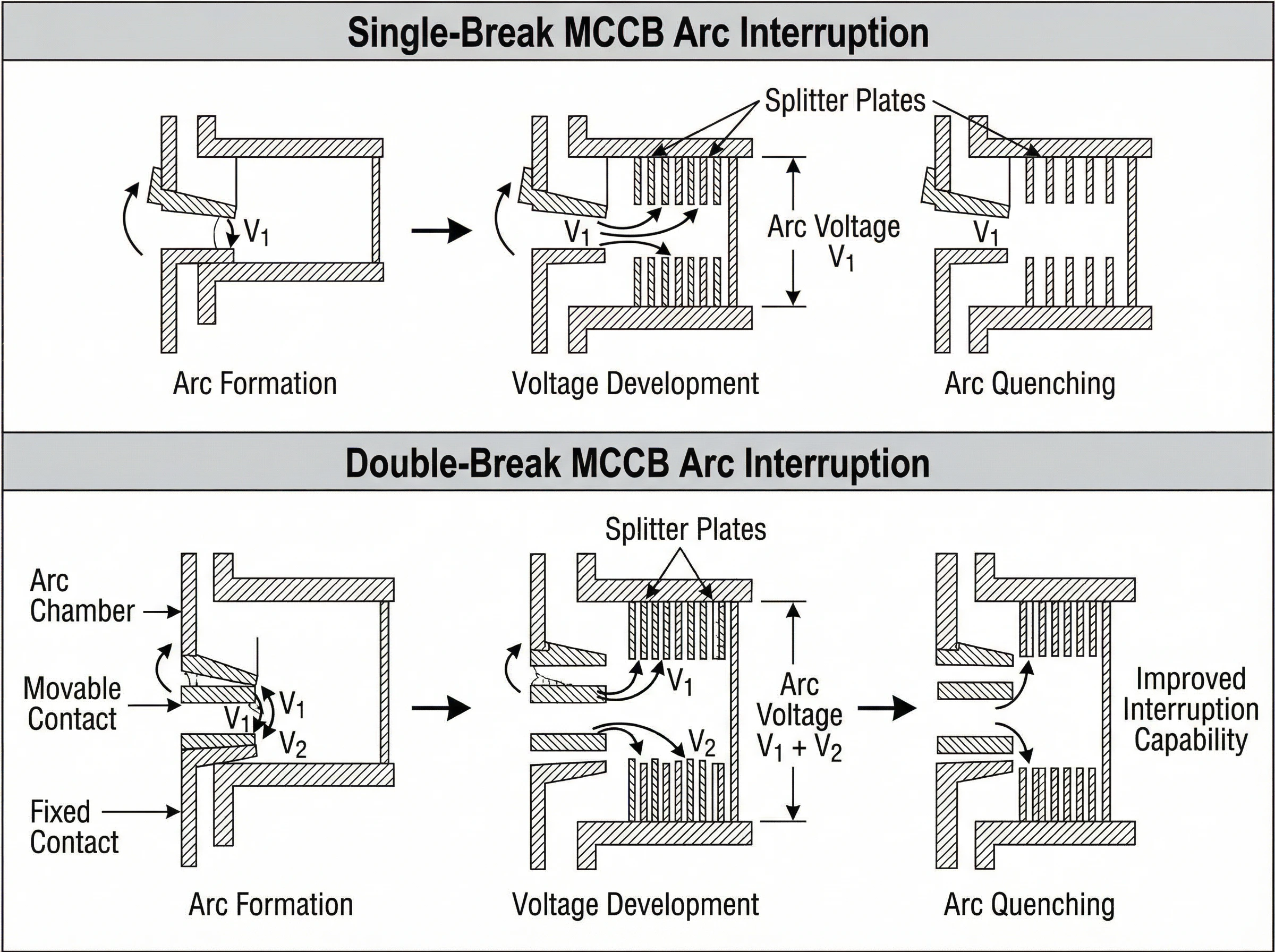
电弧电压如何驱动分断
电弧分断依赖于建立足够的电弧电压来抗衡系统电压并驱使电流趋近于零。随着触头间隙扩大以及电弧与电弧室相互作用(通过分割板冷却、拉伸和分割),电弧电压上升。一旦在电流过零点(交流系统中)电弧电压超过系统恢复电压,电弧即熄灭,断路器成功分断故障。.
关键原理:更高的电弧电压 = 更快的电流衰减 = 更强的限流能力。.
单断口电弧特性
在单断口塑壳断路器中,每极产生一个电弧。电弧电压取决于:
- 触头分离距离
- 灭弧室设计(隔弧板数量与间距)
- 磁吹强度(如具备)
- 灭弧室内的电弧冷却速率
典型的单断口电弧电压范围在30V至100V之间,具体取决于灭弧室设计和电流水平。断路器必须依靠高效的灭弧室结构和快速的触头运动来实现快速限流。.
性能考量:
- 电弧能量集中于单一灭弧室,该灭弧室必须承受全部的热应力和压力应力
- 在高故障电流下,要达到足够的电弧电压可能需要更长的触头行程或更激进的灭弧室设计
- 在低故障电流下,单断口设计已展现出稳定的性能,未出现某些双断口结构中观察到的瞬态再闭合现象
双断口电弧特性
在双断口塑壳断路器中,每极形成两个串联电弧。总电弧电压近似为两个电弧电压之和:
V_总电弧 ≈ V_电弧1 + V_电弧2
若每段电弧产生50V电压,总电弧电压可达100V——这是具有相似灭弧室特性的可比单断点设计的两倍。更高的电压可驱动更快的di/dt(电流下降率),提供更强的限流能力。.
性能考量:
- 更高的电弧电压可加速限流过程,降低允通峰值电流和I²t能量
- 紧凑灭弧室内的两段电弧会产生更高压力和材料蒸发,需要更坚固的灭弧室材料和泄压设计
- 在低故障电流水平下,部分双断点设计曾在分断过程中出现触头重闭合现象,导致允通能量(I²t和电弧能量)瞬时增加;此现象具有设计特异性,并非所有双断点MCCB的普遍特性
- 合理的灭弧室设计必须控制两段电弧间的相互作用,以避免电弧失稳
灭弧室设计权衡
两种设计均依赖带栅片(亦称灭弧栅)的灭弧室来冷却和熄灭电弧。灭弧室将电弧分割为多个串联的小电弧,从而提高总电弧电压。.
单断点灭弧室:专注于最大化单电弧路径的电压提升。根据电压和分断能力通常使用10-20片灭弧栅片。灭弧室容积与栅片间距针对单电弧冷却进行优化。.
双断点灭弧室:必须同时处理两段电弧。在双电弧共享灭弧室空间的紧凑设计中,压力和烧蚀更为严重。部分制造商采用每段电弧独立灭弧室;其他制造商则针对双电弧管理优化共享灭弧室设计。.
两种设计的有效性高度取决于实施质量——灭弧栅片材料(钢、铜、陶瓷涂层)、间距、磁场强度和灭弧室泄压。不能简单概括为“双断点始终更优”或反之;依据IEC 60947-2序列进行的特定产品测试才是唯一可靠的性能指标。.
分断能力与IEC 60947-2标准
IEC 60947-2是定义低压断路器(包括所有MCCB)性能要求和测试程序的国际标准。理解该标准如何评估分断能力,有助于客观比较单断点与双断点技术。.
Icu:额定极限短路分断能力
Icu 表示断路器在额定电压下能够成功分断且不被损毁的最大预期故障电流(单位kA)。这是断路器的绝对极限值——依据IEC标准序列III(试验任务1:O-t-CO)进行测试。.
在完成Icu级别的故障分断后,断路器可能不再适合继续使用。标准要求验证设备已成功分断电路且未发生起火或爆炸,但未要求其在分断后仍保持可运行状态。.
选用原则:必须确保Icu ≥ 安装点的最大预期故障电流。若Icu选型不足将造成灾难性安全隐患——断路器可能在故障期间发生剧烈故障。.
Ics:额定运行短路分断能力
Ics 表示断路器能够分断 并保持可继续运行. 的故障电流水平。IEC序列II(试验任务2:O-CO-CO)对此进行验证——断路器必须在Ics水平下成功完成三次分断,且仍满足性能标准(介电试验、温升试验、操作试验)。.
IEC 60947-2规定:
- Ics ≥ Icu的25%(最低要求)
- 通常实践目标为Icu的50%、75%或100%
- 高端塑壳断路器可实现Ics = Icu(100%),这意味着断路器即使在分断其最大额定故障电流后仍保持可继续使用的状态。
Ics的重要性:在需要快速恢复供电的关键设施中(医院、数据中心、工业流程),应尽可能选择Ics接近Icu的断路器。若故障电流为40kA,选用额定值Icu = 50kA / Ics = 50kA(100%)的断路器可确保设备在承受40kA故障后仍能正常运行。而额定值Icu = 50kA / Ics = 25kA(50%)的断路器在经历相同故障后可能需要更换。.
触头设计是否影响Icu/Ics?
无论是单断点还是双断点塑壳断路器,均可实现高Icu和Ics额定值——触头结构本身并不决定分断能力。关键在于完整的极柱设计:
- 触头材料与质量(镀银铜、钨铜合金)
- 灭弧室效能(分割栅片、磁场设计、冷却效果)
- 触头组件与操作机构的机械强度
- 热管理(散热能力、材料耐热性)
您会发现既有额定Icu达100kA的单断点MCCB,也有额定Icu为50kA的双断点MCCB,反之亦然。单断点与双断点的设计选择只是众多因素之一。务必核实制造商声明的Icu与Ics值——这些才是性能的唯一可靠指标。.
选择性与协调配合
IEC 60947-2采用 过电流选择性 (原称“级差配合”)这一术语来描述上下游保护装置之间的协调配合。正确的选择性可确保仅最靠近故障点的下游断路器脱扣,而上游断路器保持闭合,从而维持非故障回路的供电。.
单断点与双断点塑壳断路器在适当协调配合下均可实现选择性。协调配合取决于时间-电流特性曲线、脱扣单元设定值(热磁阈值)以及各装置的限流性能。制造商提供的选择性表格会明确显示在特定故障电流水平下可实现完全选择性的断路器组合。.
在高故障电流设施中,设计优良的双断点MCCB具有更强的限流能力,可通过降低允通电流和上游设备的I²t应力来提升选择性。但这是产品特性相关的结论——应使用制造商数据验证协调配合性,而非基于触头设计的通用假设。.
مقایسه عملکرد
基准测试和现场数据表明,单断点和双断点塑壳断路器根据故障电流水平、灭弧室设计和应用场景展现出不同的性能特征。两种技术均非普遍优越——各自在特定场景中表现更佳。.
高故障电流性能(>20kA)
在高预期故障电流下,有效的限流对于保护下游设备和电缆免受过度热应力与机械应力至关重要。.
双断点优势:
- 串联的两个电弧产生更高的总电弧电压,加速电流衰减
- 更快的di/dt(电流下降率)降低允通峰值电流
- 传递至下游电路的更低I²t能量减少电缆和母排的热应力
- 更强的限流能力可通过降低故障电流幅值提升与下游设备的选择性
双断点挑战:
- 更高的灭弧室压力与材料蒸发需要坚固的灭弧室设计和排气结构
- 紧凑灭弧室内两个电弧的相互作用要求精确的腔体几何结构以避免不稳定性
- 触头组件和操作机构承受更大的机械应力
高故障电流下的单断点设计单断点塑壳断路器可通过优化灭弧室实现高分断能力(80-100kA Icu),但与同等级双断点设计相比可能产生略高的允通电流和I²t。随着灭弧室设计的改进,该差异正在缩小——采用先进栅片阵列和磁吹技术的现代单断点塑壳断路器已具备竞争优势。.
中低故障电流性能(5-20kA)
在此工况下,绝对限流并非关键——故障电流可在无需极高电弧电压的情况下得到控制。稳定且一致的分断行为更为重要。.
单断点优势:
- 更简单的触头机构与更少的活动部件降低了机械故障的可能性
- 电弧能量集中于单一灭弧室简化了热管理
- 基准测试表明在此故障范围内可实现稳定分断,且无瞬态再闭合现象
- 更低的灭弧室压力与烧蚀程度可能延长触头寿命
双断点挑战:
- 部分双断点设计在低等级故障期间曾出现触头再闭合现象,瞬时增大了允通I²t与电弧能量
- 此行为具有设计特异性(并非所有双断点MCCB的共性问题),取决于触头动态特性、弹簧张力与灭弧室压力的相互作用
- 在较低故障电流下,双断点的限流优势减弱——当故障电流已处于中等水平时,更高的电弧电压带来的效益有限
中低故障等级下的双断点表现设计优良的双断点MCCB能在整个故障范围内可靠运行。再闭合问题是设计缺陷,而非该技术固有的局限性。需核查具体产品的测试数据——信誉良好的制造商会公布全故障范围的时间-电流曲线与允通特性。.
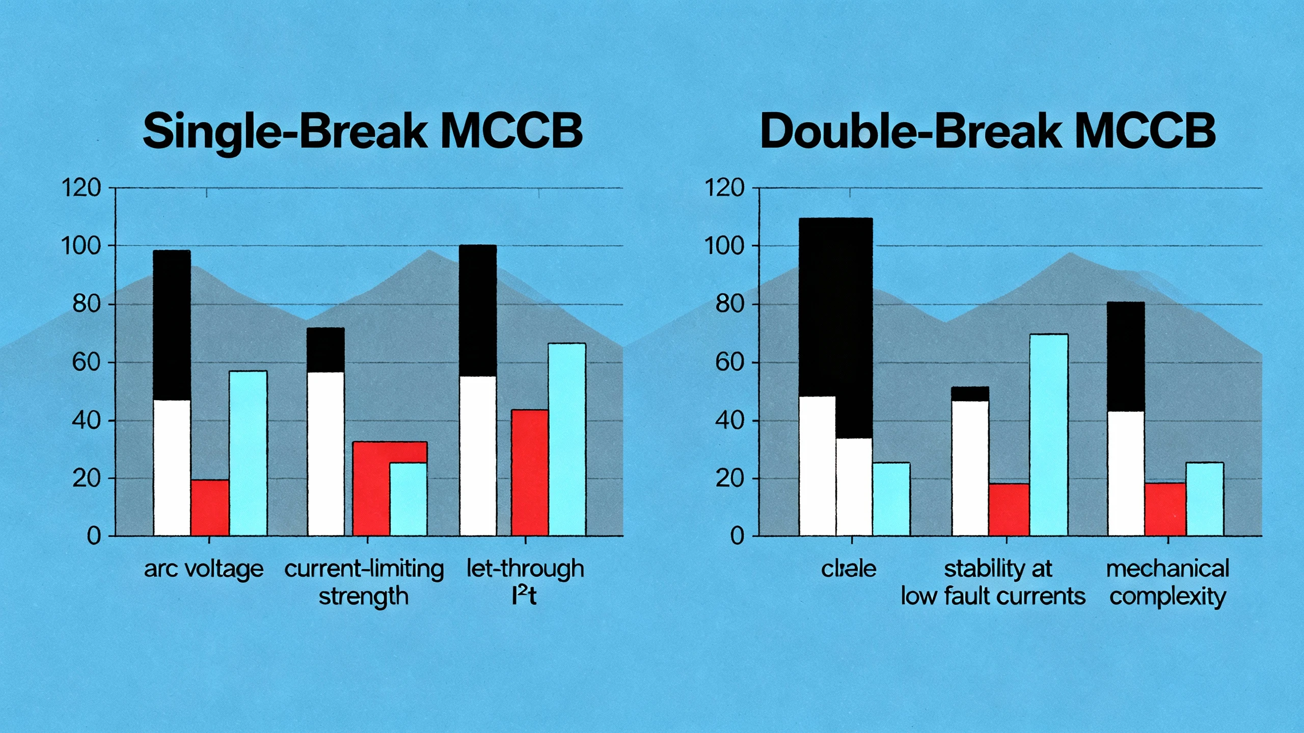
限流特性
限流型MCCB通过快速建立电弧电压,将峰值故障电流抑制在预期(可用)故障电流之下。此举可保护下游设备并提升协调性。.
| 性能指标 | 单断点(典型) | 双断点(典型) |
| 每间隙电弧电压 | 30-100V(单个电弧) | 每电弧 30-100V(×2) |
| 总电弧电压 | 30-100V | 60-200V |
| 限流强度 | متوسط تا زیاد | 高至极高 |
| 允通 I²t(高故障电流) | متوسط | کم تا متوسط |
| 稳定性(低故障电流) | 高(性能一致) | 可变(取决于设计) |
| 允通峰值电流 | 10-30kA(在 50kA 预期短路电流条件下) | 8-25kA(可提供50kA规格) |
注:所列数值为示例。实际性能取决于具体产品设计、框架尺寸及灭弧室优化。请务必参考制造商数据。.
机械可靠性与使用寿命
在额定限值内正确应用时,两种设计均可提供长久的使用寿命。.
单断点:运动部件较少、触头结构更简单,通常意味着机械复杂性较低。电弧烧蚀集中于单一灭弧室,在高负荷应用(频繁的大电流分断)中可能加速触头磨损。.
双断点:结构更为复杂,具有额外的触头界面。电弧能量分布在两个灭弧室,可能降低每个灭弧室的烧蚀,但紧凑的双弧室中更高的压力和温度可能抵消此优势。.
维护周期与预期使用寿命更多取决于工作制、故障频率和环境条件,而非触头设计。IEC 60947-2的机械耐久性测试(分合循环)对两种技术同样适用。.
成本与尺寸考量
成本与物理尺寸主要由制造商特定因素决定。在未比较具体产品前,无法可靠得出“单断点更便宜”或“双断点更紧凑”的结论。.
一般性观察:
- 两种设计均覆盖完整的塑壳断路器电流范围(16A至1600A)
- 高端特性(电子脱扣单元、通信功能、高Ics/Icu)对成本的影响大于触头配置
- 框架尺寸与分断能力(Icu)决定物理尺寸——无论是单断点还是双断点,一台630A/85kA的塑壳断路器所占空间大致相同
在对比报价时,需评估整体拥有成本:断路器价格、配电盘空间、协调配合性能及预期使用寿命。触头设计是此项分析的一个组成部分,而非决定性因素。.
选型标准:不同技术的适用场景
“更优”的塑壳断路器是符合您具体应用需求、故障条件和保护目标的产品。请依据以下标准指导您的规格选择。.
在以下情况选择双断点塑壳断路器:
1. 高故障电流环境(>30kA)
若短路分析显示安装点预期故障电流超过30kA,具备强限流能力的双断点设计具有明显优势:
- 降低的峰值允通电流可保护下游设备免受机械应力损害
- 更低的I²t能量值可减轻电缆、母线及连接设备的热应力
- 通过有效降低故障电流,提升与下游断路器的选择性配合能力
应用示例:计算故障电流为55kA的1600kVA变压器次级侧主进线塑壳断路器。选用额定电流800A/分断能力65kA Icu且具备强限流功能的双断点塑壳断路器,可减轻下游馈线的应力并提升整体系统协调性。.
2. 变压器次级保护
变压器次级回路会承受高涌流(8-12倍额定电流)和高可用故障电流。配备电子脱扣器的双断点塑壳断路器可提供:
- 可调节脱扣设定值(Ir, Isd),既能避免涌流引起的误脱扣,又能保持故障保护功能
- 强电流限制,以保护变压器绕组和二次母线免受高故障应力影响
- 与下游配电断路器实现更好的选择性配合
3. 需要最大电流限制的关键设施
优先考虑最小化故障能量的应用场景:
- 配备敏感电子设备的数据中心
- 设有关键生命支持系统的医院
- 拥有对电压暂降敏感的高价值机械设备的工业流程
- 带有长垂直母线竖井的高层建筑
4. 当制造商测试数据确认其具有卓越性能时
若比较特定塑壳断路器型号,且双断点选项在IEC测试报告中显示出可测量的更优电流限制能力、更低的I²t值以及在故障范围内经过验证的稳定性——则应选择双断点设计。.
在以下情况选择单断点塑壳断路器:
1. 中低故障电流应用场景(10-30kA)
在故障电流水平中等的商业建筑、轻工业设施或分支馈线中,单断点塑壳断路器可提供可靠的保护,且无需双断点设计的复杂性:
- 结构更简单,运动部件更少,减少了潜在的故障点
- 在整个故障范围内具有稳定的分断性能
- 降低腔体压力与侵蚀可延长使用寿命
应用示例办公楼400A额定分支配电线路,故障等级为25kA。采用400A/36kA Icu额定值的单断点塑壳断路器可提供充分保护、可靠协调且具备成本效益。.
2. 电机保护与控制电路
电机馈线通常承受中等故障电流及频繁切换操作。单断点塑壳断路器具备以下优势:
- 坚固触头设计,适应频繁机械操作
- 可调磁脱扣设定值(Im),适应电机启动涌流
- 可靠过载保护(Ir),避免过度限流影响电机启动
3. 对成本敏感且无极端故障等级的项目
当预算受限且故障电流工况无需最大限流能力时,单断点塑壳断路器能以更经济的成本提供符合规范的保护。需验证:
- Icu ≥ 预期故障电流
- Ics符合运行可靠性要求(建议达到Icu的75%-100%)
- 与上下游设备协调性已验证
4. 注重成熟现场应用表现的场景
若贵方设施或机构对特定单断点塑壳断路器型号具有长期积极使用经验——包括已知可靠性、稳定性能及成熟的维护流程——保持设备延续性可能带来运营优势。.
ماتریس تصمیمگیری
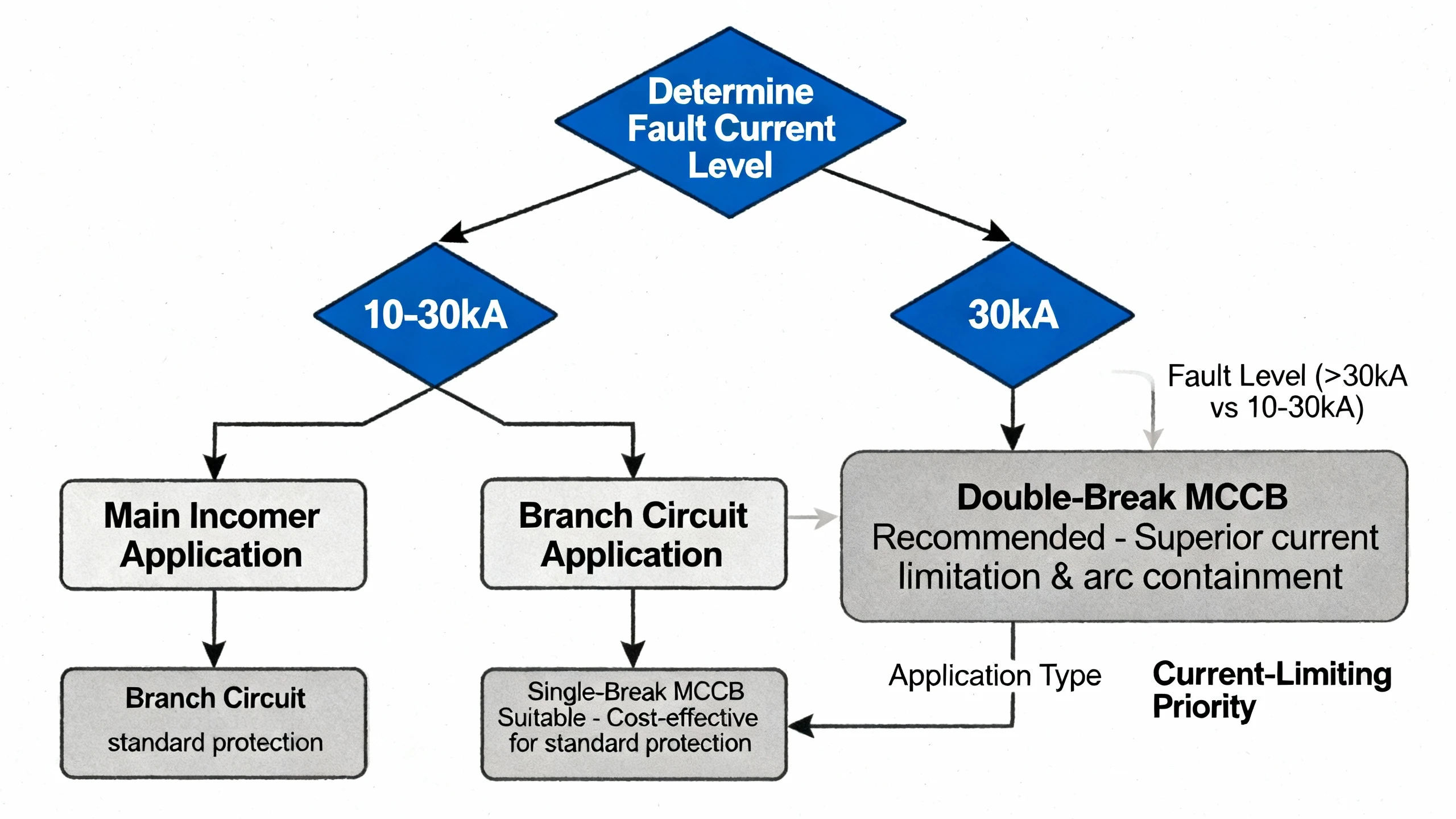
通用选择规则(适用于两种技术)
| انتخاب عامل | 优选单断点 | 优选双断点 |
| 预期故障电流 | 10-30千安 | >30千安 |
| نوع برنامه | 分支馈线、电动机、次干线 | 主进线、变压器二次侧. |
| 限流优先级 | 中等(标准保护) | 高(最小化允通I²t) |
| 选择性要求 | 标准协调 | 紧密选择性,复杂系统 |
| نصب و راه اندازی محیط زیست | 商业、轻工业 | 重工业、数据中心 |
| 预算限制 | پروژههای حساس به هزینه | 性能优先 |
| 机械结构简洁性 | 倾向于较少运动部件 | 为性能可接受复杂度 |
| 运行可靠性(Ics) | 可接受50-75% Icu | 目标Ics = 100% Icu |
| 下游设备敏感性 | 标准电缆、配电盘 | 敏感电子设备、关键负载 |
无论触点配置如何,每个MCCB选型必须满足:
- Icu ≥ 最大预期故障电流:不可协商。进行短路研究,并验证断路器的Icu额定值在额定电压下满足或超过计算出的故障水平。.
- Ics 需符合应用关键性要求:对于关键设施(医院、数据中心、连续工业流程),应规定Ics为Icu的75%-100%,以确保断路器在故障分断后仍可继续使用。.
- 已验证协调性:使用制造商的时间-电流曲线和选择性表格来确认上游/下游协调性。切勿基于触头设计假设协调性——需使用具体产品数据进行验证。.
- 符合IEC 60947-2标准:确认该MCCB带有IEC标志,并已按照该标准的测试序列进行型式试验。若为关键应用选型,应要求提供测试证书。.
- 参考制造商应用指南:主要MCCB制造商(施耐德、ABB、西门子、伊顿、VIOX)均发布应用指南和白皮书,对比其单断点和双断点产品。请使用这些资源——它们提供产品特定的测试数据和选型工具。.
توصیه نهایی
切勿仅基于“单断点与双断点”的市场宣传来选择MCCB。两种技术均已成熟、可靠且广泛应用。正确的选择取决于:
- 您安装点的故障电流特性(短路研究结果)
- 应用类型和关键性(主回路与分支回路,关键与标准)
- 协调性要求(选择性表格和时间-电流分析)
- 制造商特定的测试数据(Icu、Ics、I²t允通能量、时间-电流曲线)
首先进行短路研究,明确保护需求,随后评估符合这些要求的具体MCCB型号(不考虑触头设计)。触头配置是需要关注的技术细节——但并非首要决策依据。.
نتيجه گيری
“单断点与双断点MCCB孰优孰劣?”这一问题并无通用答案。两种触头配置均符合IEC 60947-2标准,能提供可靠的故障保护,并各自适用于不同的应用场景。.
双断点MCCB在高故障电流环境(>30kA)中表现卓越,其强效的限流特性可降低下游设备承受的应力并提升系统协调性。更高的电弧电压能加速电流衰减,使其特别适用于主进线、变压器次级及对通过能量控制要求严格的关键设施。.
单断点MCCB为中等级别故障电流(10-30kA)应用提供可靠且经济高效的保护。其更简洁的机械结构和在故障范围内的稳定分断性能,使其非常适合分支馈线、电机回路及无需极端限流的商业设施。.
正确选择取决于短路研究结果、应用关键性及协调要求——而非触头设计优越性的市场宣传。应从故障电流分析入手,明确保护目标(Icu、Ics、限流特性、选择性),再根据制造商测试数据选择符合要求的MCCB。.
两种技术均已成熟并经现场验证,在正确选型条件下均能实现长久使用寿命。重点关注断路器性能特性与安装场所保护需求的匹配,即可实现可靠且符合规范的电能保护,与触头配置无关。.
