
Η κατανόηση των βασικών ηλεκτρικών στοιχείων είναι ζωτικής σημασίας για όποιον ασχολείται με έργα DIY ή μελετά ηλεκτρονικά. Η διαφορά μεταξύ βολτ και ρεύματος είναι μια από τις πιο θεμελιώδεις έννοιες που θα συναντήσετε, ωστόσο συχνά παρερμηνεύεται. Αυτός ο περιεκτικός οδηγός θα σας καθοδηγήσει σε όλα όσα πρέπει να γνωρίζετε για την τάση έναντι του ρεύματος, μαζί με πρακτικά παραδείγματα, συμβουλές ασφαλείας και πρακτικά έργα που ζωντανεύουν αυτές τις έννοιες.
Κατανόηση των βασικών ηλεκτρικών αρχών μέσω βολτ και ρεύματος
Πριν εμβαθύνουμε στις τεχνικές λεπτομέρειες, ας προσδιορίσουμε τι κάνει τα βολτ και το ρεύμα τόσο σημαντικά στις ηλεκτρικές εργασίες. Είτε είστε φοιτητής που μαθαίνει βασικές αρχές της ηλεκτρολογίας είτε λάτρης των DIY που σχεδιάζει το πρώτο του ηλεκτρονικό έργο, η κατανόηση αυτών των εννοιών είναι απαραίτητη τόσο για την ασφάλεια όσο και για την επιτυχία.
Η ηλεκτρική ενέργεια ρέει μέσω κυκλωμάτων ακολουθώντας προβλέψιμα μοτίβα, όπως ακριβώς το νερό ρέει μέσω σωλήνων. Αυτή η αναλογία με το νερό θα αποτελέσει τη βάση μας για την κατανόηση τόσο της τάσης όσο και του ρεύματος, καθιστώντας τις σύνθετες ηλεκτρικές έννοιες προσβάσιμες και αξιομνημόνευτες.
Μαθησιακοί στόχοι για αυτόν τον οδηγό:
- Κατανοήστε τι αντιπροσωπεύουν η τάση και το ρεύμα στα ηλεκτρικά κυκλώματα
- Μάθετε πρακτικές διαφορές μεταξύ βολτ και ρεύματος
- Ανακαλύψτε πώς να μετράτε και να εργάζεστε με ασφάλεια με ηλεκτρικές τιμές
- Ολοκληρώστε πρακτικά έργα που επιδεικνύουν αυτές τις έννοιες
- Αναπτύξτε δεξιότητες αντιμετώπισης προβλημάτων για συνηθισμένα ηλεκτρικά προβλήματα
Προεπισκόπηση ασφαλείας: Σε όλο αυτόν τον οδηγό, θα τονίσουμε την ηλεκτρική ασφάλεια για τις εργασίες DIY. Να θυμάστε ότι ακόμη και τα κυκλώματα χαμηλής τάσης μπορεί να είναι επικίνδυνα αν δεν χειριστούν σωστά και ότι η τάση δικτύου (οικιακές ηλεκτρικές εγκαταστάσεις) πρέπει να πραγματοποιείται μόνο από εξειδικευμένους ηλεκτρολόγους.
Τάση που εξηγείται με παραδείγματα από τον πραγματικό κόσμο
Η τάση, μετρούμενη σε βολτ (V), αντιπροσωπεύει την ηλεκτρική πίεση ή τη διαφορά δυναμικού. Σκεφτείτε την τάση όπως η πίεση του νερού στο υδραυλικό σύστημα του σπιτιού σας. Όπως η πίεση του νερού ωθεί το νερό μέσα από τους σωλήνες, έτσι και η τάση ωθεί το ηλεκτρικό ρεύμα μέσα από αγωγούς όπως τα καλώδια.
Η αναλογία με την πίεση του νερού
Φανταστείτε ότι έχετε δύο δεξαμενές νερού σε διαφορετικά ύψη. Η δεξαμενή που βρίσκεται ψηλότερα έχει μεγαλύτερη βαρυτική δυναμική ενέργεια, δημιουργώντας υψηλότερη πίεση νερού στο κάτω μέρος. Ομοίως, η τάση αντιπροσωπεύει τη διαφορά ηλεκτρικού δυναμικού μεταξύ δύο σημείων σε ένα κύκλωμα. Όσο μεγαλύτερη είναι η τάση, τόσο περισσότερη «ηλεκτρική πίεση» είναι διαθέσιμη για να ωθήσει το ρεύμα μέσω του κυκλώματος.
Βασικά χαρακτηριστικά της τάσης:
- Μετρημένο σε βολτ (V)
- Αντιπροσωπεύει τη διαφορά ηλεκτρικού δυναμικού
- Μπορεί να υπάρχει χωρίς ροή ρεύματος (σαν μια μπαταρία που κάθεται σε ένα ράφι)
- Οδηγεί το ρεύμα μέσω της αντίστασης στα κυκλώματα
- Υψηλότερη τάση σημαίνει μεγαλύτερη ηλεκτρική πίεση
Τάση σε καθημερινές εφαρμογές
Συνηθισμένα επίπεδα τάσης που θα συναντήσετε:
- Οικιακή μπαταρία AA: 1,5V DC
- Μπαταρία αυτοκινήτου: 12V DC
- Φόρτιση USB: 5V DC
- Οικιακές πρίζες: 120V AC (ΗΠΑ) ή 240V AC (Ευρώπη)
- Γραμμές υψηλής τάσης: 10.000V+ AC
Η κατανόηση αυτών των επιπέδων τάσης είναι ζωτικής σημασίας για την ηλεκτρική ασφάλεια. Ενώ μια μπαταρία 1,5V είναι ασφαλής στη χρήση, η τάση του σπιτιού μπορεί να είναι θανατηφόρα. Να χρησιμοποιείτε πάντα τα κατάλληλα μέτρα ασφαλείας και ποτέ να μην εργάζεστε με τάση δικτύου χωρίς την κατάλληλη εκπαίδευση.
Μέτρηση τάσης με ασφάλεια
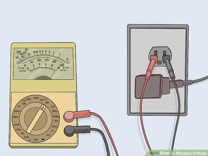
Πίστωση σε WIKIHOW
Για να μετρήσετε την τάση, θα χρησιμοποιήσετε ένα πολύμετρο ρυθμισμένο στη συνάρτηση τάσης (V). Σημαντική σημείωση ασφαλείας: Ξεκινάτε πάντα με το υψηλότερο εύρος τάσης στο πολύμετρό σας και μειώστε την τάση για να αποφύγετε την πρόκληση ζημιάς στο όργανο ή τη δημιουργία κινδύνων για την ασφάλεια.
Βασικά βήματα μέτρησης τάσης:
- Απενεργοποιήστε την παροχή ρεύματος στο κύκλωμα (όταν είναι δυνατόν)
- Ρυθμίστε το πολύμετρο στο κατάλληλο εύρος τάσης
- Συνδέστε τους αισθητήρες στο εξάρτημα ή στην πηγή τροφοδοσίας
- Διαβάστε την τιμή εμφάνισης
- Κόκκινος αισθητήρας στο θετικό, μαύρος αισθητήρας στο αρνητικό για τάση DC
Κοινές εφαρμογές μέτρησης τάσης:
- Έλεγχος επιπέδων φόρτισης μπαταρίας
- Επαλήθευση εξόδων τροφοδοτικού
- Αντιμετώπιση προβλημάτων κυκλώματος
- Έλεγχος πτώσεων τάσης εξαρτημάτων
Απλοποιημένο για αρχάριους και έργα DIY
Το ρεύμα, μετρούμενο σε αμπέρ ή αμπέρ (A), αντιπροσωπεύει τη ροή του ηλεκτρικού φορτίου. Συνεχίζοντας την αναλογία μας με το νερό, αν η τάση είναι ίση με την πίεση του νερού, τότε το ρεύμα είναι ίσο με την ποσότητα νερού που ρέει μέσω του σωλήνα ανά δευτερόλεπτο.
Κατανόηση της ροής ρεύματος
Το ρεύμα ρέει όταν εφαρμόζεται τάση σε μια αντίσταση, δημιουργώντας μια πλήρη ηλεκτρική διαδρομή που ονομάζεται κύκλωμα. Η βασική εικόνα: Το ρεύμα δεν «εξαντλείται» σε ένα κύκλωμα—ρέει σε έναν πλήρη βρόχο, επιστρέφοντας στην πηγή του. Αυτό είναι παρόμοιο με τον τρόπο που ρέει το νερό μέσω ενός κλειστού βρόχου υδραυλικού συστήματος.
Βασικές σύγχρονες έννοιες:
- Μετράται σε αμπέρ (A) ή μιλιαμπέρ (mA)
- Αντιπροσωπεύει τον ρυθμό ροής του ηλεκτρικού φορτίου
- Απαιτείται μια πλήρης διαδρομή κυκλώματος για ροή
- Το ίδιο ρεύμα ρέει μέσω όλων των εξαρτημάτων σε ένα κύκλωμα σε σειρά
- Ρεύμα διαιρείται σε παράλληλα κυκλώματα
Τρέχουσα σε Πρακτικές Εφαρμογές
Τυπικές απαιτήσεις ρεύματος για κοινές συσκευές:
- Ενδεικτική λυχνία LED: 10-20 mA
- Μικρός κινητήρας: 100-500 mA
- Φόρτιση smartphone: 1-2 Α
- Λάμπα οικιακού φωτισμού: 0,5-1 Α
- Ηλεκτρικός βραστήρας: 10-15 Α
Η κατανόηση αυτών των επιπέδων ρεύματος σάς βοηθά να επιλέξετε τα κατάλληλα εξαρτήματα και μέτρα ασφαλείας για τα ηλεκτρικά σας έργα DIY.
Μέτρηση ρεύματος με ασφάλεια
Η μέτρηση ρεύματος απαιτεί διακοπή του κυκλώματος, σε αντίθεση με τη μέτρηση τάσης που γίνεται σε όλα τα εξαρτήματα. Αυτό καθιστά τη μέτρηση ρεύματος ελαφρώς πιο περίπλοκη αλλά εξίσου σημαντική για την αντιμετώπιση προβλημάτων.
Τρέχουσα διαδικασία μέτρησης:
- Απενεργοποιήστε την παροχή ρεύματος στο κύκλωμα
- Διακόψτε το κύκλωμα στο σημείο όπου θέλετε να μετρήσετε το ρεύμα
- Ρυθμίστε το πολύμετρο στο κατάλληλο εύρος ρεύματος
- Συνδέστε το πολύμετρο σε σειρά με το κύκλωμα
- Επαναφέρετε την τροφοδοσία και διαβάστε τη μέτρηση
- Απενεργοποιήστε την παροχή ρεύματος πριν αφαιρέσετε το πολύμετρο
Προειδοποίηση ασφαλείας: Μην επιχειρήσετε ποτέ να μετρήσετε το ρεύμα τοποθετώντας αισθητήρες πολύμετρου σε μια πηγή ρεύματος—αυτό θα δημιουργήσει βραχυκύκλωμα και μπορεί να προκαλέσει ζημιά στον εξοπλισμό ή τραυματισμό.
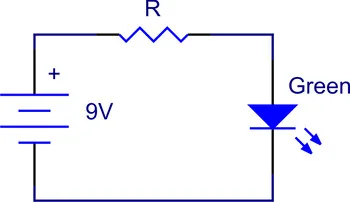
Παράδειγμα κυκλώματος LED
Ας εξετάσουμε ένα απλό κύκλωμα LED για να δείξουμε τη ροή ρεύματος:
- Μπαταρία 9V παρέχει τάση (ηλεκτρική πίεση)
- Αντίσταση 330Ω περιορίζει τη ροή ρεύματος
- LED μετατρέπει την ηλεκτρική ενέργεια σε φως
- Ροές ρεύματος από το θετικό της μπαταρίας, μέσω της αντίστασης, μέσω της λυχνίας LED, πίσω στο αρνητικό της μπαταρίας
Σε αυτό το κύκλωμα, το ίδιο ρεύμα ρέει μέσω όλων των εξαρτημάτων, συνήθως περίπου 20 mA με τις τιμές που δίνονται.
Πρακτικές διαφορές μεταξύ βολτ και ρεύματος
Τώρα που κατανοούμε την τάση και το ρεύμα ξεχωριστά, ας διερευνήσουμε τις πρακτικές διαφορές τους και τον τρόπο με τον οποίο αλληλεπιδρούν σε πραγματικά ηλεκτρικά συστήματα. Αυτή η ενότητα είναι ζωτικής σημασίας για όποιον σχεδιάζει DIY ηλεκτρικά έργα ή μελετά τα βασικά της ηλεκτρολογίας.
Σύγκριση δίπλα-δίπλα
| Όψη | Τάση (Βολτ) | Ρεύμα (Αμπέρ) |
|---|---|---|
| Ορισμός | Ηλεκτρική πίεση/διαφορά δυναμικού | Ρυθμός ροής ηλεκτρικού φορτίου |
| Αναλογία με το Νερό | Πίεση νερού | Ρυθμός ροής νερού |
| Σύμβολο | V | Εγώ ή Α |
| Μέτρηση | Σταυρωτά στοιχεία (παράλληλα) | Μέσω εξαρτημάτων (σειρά) |
| Απαιτήσεις κυκλώματος | Μπορεί να υπάρχει χωρίς ρεύμα | Απαιτείται πλήρες κύκλωμα |
| Ανησυχία για την ασφάλεια | Υψηλή τάση = κίνδυνος ηλεκτροπληξίας | Υψηλό ρεύμα = κίνδυνος πυρκαγιάς/εγκαύματος |
| Σχέση | Οδηγεί το ρεύμα μέσω της αντίστασης | Ελέγχεται από τάση και αντίσταση |
Νόμος του Ωμ: Η θεμελιώδης σχέση
Η σχέση μεταξύ τάσης, ρεύματος και αντίστασης ακολουθεί τον νόμο του Ohm: V = I × R
Αυτή η θεμελιώδης εξίσωση δείχνει πώς αλληλεπιδρούν η τάση, το ρεύμα και η αντίσταση:
- Αύξηση τάσης: Το ρεύμα αυξάνεται (αν η αντίσταση παραμείνει η ίδια)
- Αύξηση αντίστασης: Το ρεύμα μειώνεται (αν η τάση παραμείνει η ίδια)
- Διπλασιάστε την τάση: Το ρεύμα διπλασιάζεται (με σταθερή αντίσταση)
Πρακτικές εφαρμογές του νόμου του Ohm:
- Υπολογισμός τιμών αντίστασης LED
- Προσδιορισμός απαιτήσεων ισχύος
- Αντιμετώπιση προβλημάτων κυκλώματος
- Σχεδιασμός ασφαλών ηλεκτρικών συστημάτων
Υπολογισμοί τάσης έναντι ρεύματος σε ισχύ
Η ισχύς (μετρούμενη σε watt) συνδυάζει τάση και ρεύμα: P = V × I
Η κατανόηση της δύναμης σας βοηθά να:
- Επιλέξτε κατάλληλα τροφοδοτικά
- Υπολογίστε τη διάρκεια ζωής της μπαταρίας
- Βεβαιωθείτε ότι τα εξαρτήματα μπορούν να αντέξουν ηλεκτρικά φορτία
- Σχεδιάστε αποτελεσματικά ηλεκτρικά συστήματα
Παράδειγμα υπολογισμού:
Ένα σχέδιο κυκλώματος 12V 2A καταναλώνει: P = 12V × 2A = 24 watt
Αυτά τα ίδια 24 watt θα μπορούσαν να είναι: 24V × 1A ή 6V × 4A
Επιπτώσεις στην ασφάλεια
Διαφορετικοί συνδυασμοί τάσης και ρεύματος δημιουργούν διαφορετικά ζητήματα ασφαλείας:
Υψηλή τάση, χαμηλό ρεύμα (στατικός ηλεκτρισμός):
- Μπορεί να προκαλέσει σοκαριστική αίσθηση
- Γενικά δεν είναι θανατηφόρο λόγω χαμηλού ρεύματος
- Μπορεί να προκαλέσει ζημιά σε ευαίσθητα ηλεκτρονικά είδη
Χαμηλή τάση, υψηλό ρεύμα (μπαταρία αυτοκινήτου):
- Ασφαλή επίπεδα τάσης (12V)
- Μπορεί να παράγει επικίνδυνο ρεύμα σε περίπτωση βραχυκυκλώματος
- Κίνδυνος εγκαυμάτων και πυρκαγιάς
Υψηλή τάση, υψηλό ρεύμα (οικιακό δίκτυο):
- Εξαιρετικά επικίνδυνος συνδυασμός
- Μπορεί να προκαλέσει σοβαρό τραυματισμό ή θάνατο
- Απαιτούνται επαγγελματικές ηλεκτρολογικές εργασίες
Σενάρια αντιμετώπισης προβλημάτων
Συνηθισμένα ηλεκτρικά προβλήματα και οι υπογραφές τάσης/ρεύματος που τα συνοδεύουν:
Νεκρό κύκλωμα (χωρίς τάση, χωρίς ρεύμα):
- Ελέγξτε τη σύνδεση της πηγής τροφοδοσίας
- Επαληθεύστε τους διακόπτες/ασφάλειες
- Δοκιμή για σπασμένα καλώδια
Υψηλή τάση, χωρίς ρεύμα:
- Ανοικτό κύκλωμα (διακοπή σύνδεσης)
- Αποτυχημένο στοιχείο που εμποδίζει τη ροή ρεύματος
- Λανθασμένη καλωδίωση
Κανονική τάση, υπερβολικό ρεύμα:
- Βραχυκύκλωμα ή βλάβη εξαρτήματος
- Κίνδυνος υπερθέρμανσης και πυρκαγιάς
- Απαιτεί άμεση προσοχή
Βασικές Προβλέψεις Ασφαλείας για Ηλεκτρολογικές Εργασίες
Η ασφάλεια πρέπει να είναι η ύψιστη προτεραιότητά σας όταν εργάζεστε με ηλεκτρικό ρεύμα. Ακόμη και οι κατασκευές χαμηλής τάσης DIY μπορεί να είναι επικίνδυνες εάν δεν τηρούνται οι κατάλληλες προφυλάξεις. Αυτή η ενότητα παρέχει ολοκληρωμένες οδηγίες ασφαλείας για φοιτητές και λάτρεις των κατασκεών DIY.
Οδηγίες ασφαλείας για το επίπεδο τάσης
Χαμηλή τάση (κάτω από 50V DC / 30V AC):
- Γενικά ασφαλές από ηλεκτροπληξία
- Εξακολουθεί να είναι ικανό να προκαλέσει εγκαύματα ή πυρκαγιές
- Ασφαλές για τα περισσότερα ηλεκτρονικά έργα DIY
- Να αποσυνδέετε πάντα την παροχή ρεύματος όταν τροποποιείτε κυκλώματα
Μέση τάση (50-1000V):
- Επικίνδυνος κίνδυνος ηλεκτροπληξίας και ηλεκτροπληξίας
- Απαιτείται εξειδικευμένος εξοπλισμός ασφαλείας
- Συνηθισμένο σε ορισμένες βιομηχανικές εφαρμογές
- Δεν είναι κατάλληλο για περιστασιακές εργασίες DIY
Υψηλή τάση (πάνω από 1000V):
- Έντονος κίνδυνος θανάτου ή σοβαρού τραυματισμού
- Απαιτείται επαγγελματική εκπαίδευση ηλεκτρολόγου
- Ποτέ μην επιχειρείτε DIY εργασίες σε αυτά τα επίπεδα.
- Καλέστε εξειδικευμένους ηλεκτρολόγους για οποιοδήποτε πρόβλημα με τις οικιακές ηλεκτρολογικές συσκευές
Βασικός εξοπλισμός ασφαλείας
Βασικός εξοπλισμός ασφαλείας για ηλεκτρολογικές εργασίες:
- Μονωμένα εργαλεία: Αποτρέψτε την τυχαία επαφή με τα κυκλώματα υπό τάση
- Γυαλιά ασφαλείας: Προστασία από σπινθήρες και βλάβες εξαρτημάτων
- Μονωμένο χαλάκι εργασίας: Παρέχει ηλεκτρική μόνωση
- Πολύμετρο με τις κατάλληλες ονομαστικές τιμές: Βεβαιωθείτε ότι το όργανο μπορεί να χειριστεί τις αναμενόμενες τάσεις
- Κιτ πρώτων βοηθειών: Συμπεριλάβετε θεραπεία για ηλεκτρικά εγκαύματα
Προηγμένος εξοπλισμός ασφαλείας για εργασίες υψηλότερης τάσης:
- Μονωμένα γάντια: Ονομαστική τιμή για τα αναμενόμενα επίπεδα τάσης
- Ρούχα με βαθμολογία Arc: Προστασία από ηλεκτρικά τόξα
- Ανιχνευτές τάσης: Βεβαιωθείτε ότι τα κυκλώματα είναι απενεργοποιημένα
- Εξοπλισμός κλειδώματος/σήμανσης: Αποτρέψτε την τυχαία επανενεργοποίηση
Ασφαλείς διαδικασίες εργασίας
Πριν ξεκινήσετε οποιαδήποτε ηλεκτρική εργασία:
- Απενεργοποιήστε την τροφοδοσία ρεύματος στην πηγή (διακόπτης κυκλώματος ή αποσύνδεση)
- Δοκιμάστε τον εξοπλισμό δοκιμών σας σε ένα γνωστό κύκλωμα υπό τάση
- Βεβαιωθείτε ότι το κύκλωμα είναι νεκρό χρησιμοποιώντας κατάλληλο εξοπλισμό δοκιμών
- Κλείδωμα και έξοδος με ετικέτα πηγές ενέργειας, όταν είναι δυνατόν
- Χρησιμοποιήστε κατάλληλο ατομικό προστατευτικό εξοπλισμό
Κατά τη διάρκεια ηλεκτρολογικών εργασιών:
- Εργαστείτε με το ένα χέρι όταν είναι δυνατόν (μειώνει τη διαδρομή του σοκ στην καρδιά)
- Διατηρήστε τον χώρο εργασίας καθαρό και στεγνό
- Ποτέ μην εργάζεστε μόνοι σας σε δυνητικά επικίνδυνα κυκλώματα
- Κάντε διαλείμματα για να διατηρήσετε την προσοχή σας και να αποφύγετε την κόπωση
- Διακόψτε την εργασία εάν δεν είστε σίγουροι για οποιαδήποτε διαδικασία
Διαδικασίες έκτακτης ανάγκης:
- Να γνωρίζετε τη θέση των διακοπτών κυκλώματος και των ηλεκτρικών πινάκων
- Να έχετε άμεσα διαθέσιμους τους αριθμούς επικοινωνίας έκτακτης ανάγκης
- Κατανοήστε τις βασικές πρώτες βοήθειες για ηλεκτρικούς τραυματισμούς
- Να έχετε κοντά σας πυροσβεστήρα κατάλληλο για ηλεκτρικές πυρκαγιές
Συνηθισμένα λάθη ασφαλείας που πρέπει να αποφεύγετε
Επικίνδυνες υποθέσεις που μπορούν να οδηγήσουν σε ατυχήματα:
- «Η χαμηλή τάση είναι πάντα ασφαλής» – Ακόμα και τα 12V μπορούν να προκαλέσουν πυρκαγιές σε περίπτωση βραχυκυκλώματος
- «Το ρεύμα είναι κλειστό» – Επαληθεύστε πάντα με τον κατάλληλο εξοπλισμό δοκιμών
- «Είναι απλώς ένα μικρό έργο» – Ατυχήματα συμβαίνουν συχνά σε απλές εργασίες
- «Μπορώ να χειριστώ την τάση του δικτύου» – Αφήστε τις ηλεκτρικές συσκευές σε επαγγελματίες.
Πρακτικά Έργα για την Κατανόηση των Βολτ και του Ρεύματος
Ο καλύτερος τρόπος για να κατανοήσουμε τις ηλεκτρικές έννοιες είναι μέσω της πρακτικής εφαρμογής. Αυτά τα τρία προοδευτικά έργα θα σας βοηθήσουν να βιώσετε από πρώτο χέρι τη διαφορά μεταξύ βολτ και ρεύματος, ενώ παράλληλα θα αναπτύξετε χρήσιμες δεξιότητες για μελλοντικά ηλεκτρικά έργα DIY.
Έργο 1: Βασικό κύκλωμα LED (Επίπεδο αρχαρίων)
Σκοπός: Κατανοήστε τη σχέση μεταξύ τάσης, ρεύματος και αντίστασης χρησιμοποιώντας ένα απλό κύκλωμα LED.
Απαιτούμενα υλικά:
- Μπαταρία 9V με υποδοχή
- Κόκκινο LED (5mm)
- Αντίσταση 330Ω (πορτοκαλί-πορτοκαλί-καφέ ρίγες)
- Πλέγμα ψωμιού
- Καλώδια βραχυκυκλωτήρα
- Πολύμετρο
Θέματα ασφάλειας:
- Τα 9V είναι ασφαλή για χειρισμό
- Το LED μπορεί να υποστεί ζημιά από υπερβολικό ρεύμα
- Συνδέετε πάντα τα εξαρτήματα πριν από την τροφοδοσία ρεύματος
Οδηγίες βήμα προς βήμα:
Βήμα 1: Συναρμολόγηση κυκλώματος
- Τοποθετήστε το LED στο breadboard (το μακρύτερο πόδι είναι θετικό)
- Συνδέστε αντίσταση 330Ω σε σειρά με LED
- Χρησιμοποιήστε καλώδια βραχυκύκλωσης για να ολοκληρώσετε το κύκλωμα
- Ελέγξτε ξανά τις συνδέσεις πριν από την τροφοδοσία ρεύματος
Βήμα 2: Μετρήσεις τάσης
- Ρυθμίστε το πολύμετρο σε λειτουργία τάσης DC (εύρος 20V)
- Μετρήστε την τάση της μπαταρίας (θα πρέπει να είναι περίπου 9V)
- Μετρήστε την τάση στα άκρα της λυχνίας LED (συνήθως 2-3V για την κόκκινη λυχνία LED)
- Μετρήστε την τάση στην αντίσταση (υπόλοιπη τάση)
Βήμα 3: Μέτρηση ρεύματος
- Απενεργοποιήστε την τροφοδοσία (αποσυνδέστε την μπαταρία)
- Ρυθμίστε το πολύμετρο σε λειτουργία συνεχούς ρεύματος (εύρος 200mA)
- Διακόψτε το κύκλωμα και τοποθετήστε το πολύμετρο σε σειρά
- Επανασυνδέστε την παροχή ρεύματος και μετρήστε το ρεύμα (περίπου 20mA)
Μαθησιακά αποτελέσματα:
- Οι πτώσεις τάσης στα εξαρτήματα αθροίζονται στην τάση τροφοδοσίας
- Το ίδιο ρεύμα ρέει σε σειρά μέσω όλων των εξαρτημάτων
- Η αντίσταση ελέγχει τη ροή ρεύματος μέσω του κυκλώματος
- Το LED μετατρέπει την ηλεκτρική ενέργεια σε φωτεινή ενέργεια
Συμβουλές αντιμετώπισης προβλημάτων:
- Η λυχνία LED δεν ανάβει: Ελέγξτε την πολικότητα (θετικό στο μακρύτερο σκέλος)
- Η λυχνία LED είναι πολύ φωτεινή/καίγεται: Πολύ υψηλό ρεύμα, χρειάζεται μεγαλύτερη αντίσταση
- Δεν υπάρχει ροή ρεύματος: Ελέγξτε για σπασμένες συνδέσεις
Έργο 2: Δείκτης τάσης μπαταρίας (ενδιάμεσο επίπεδο)
Σκοπός: Δημιουργήστε έναν οπτικό δείκτη τάσης χρησιμοποιώντας πολλαπλές λυχνίες LED για να κατανοήσετε την κατανομή τάσης και την κατανομή ρεύματος.
Απαιτούμενα υλικά:
- Μεταβλητή τροφοδοσία DC (0-12V) ή πολλαπλές μπαταρίες
- 5 LED (διαφορετικά χρώματα)
- 5 αντιστάσεις (220Ω η καθεμία)
- Breadboard και καλώδια jumper
- Πολύμετρο
Έννοια κυκλώματος: Αυτό το έργο δημιουργεί έναν απλό δείκτη στάθμης τάσης όπου διαφορετικά LED ανάβουν σε διαφορετικά επίπεδα τάσης, δείχνοντας πώς η τάση επηρεάζει τη ροή ρεύματος.
Οδηγίες συναρμολόγησης:
Βήμα 1: Κατασκευάστε το κύκλωμα του δείκτη
- Συνδέστε τα LED παράλληλα, το καθένα με τη δική του αντίσταση περιορισμού ρεύματος
- Χρησιμοποιήστε διαφορετικά έγχρωμα LED για να αναπαραστήσετε διαφορετικά επίπεδα τάσης
- Ξεκινήστε με μία λυχνία LED και προσθέστε άλλες σταδιακά
Βήμα 2: Δοκιμή απόκρισης τάσης
- Ξεκινήστε με είσοδο 3V (πρέπει να ανάψει μία λυχνία LED)
- Σταδιακά αυξήστε την τάση σε 6V, 9V και 12V
- Παρατηρήστε πώς ανάβουν περισσότερες λυχνίες LED καθώς αυξάνεται η τάση
- Μετρήστε το ρεύμα που διαπερνά κάθε κλάδο του κυκλώματος
Βήμα 3: Ανάλυση και μετρήσεις
- Καταγράψτε μετρήσεις τάσης και ρεύματος σε κάθε επίπεδο
- Υπολογίστε την κατανάλωση ενέργειας χρησιμοποιώντας P = V × I
- Παρατηρήστε πώς τα παράλληλα κυκλώματα διαιρούν το ρεύμα αλλά μοιράζονται την τάση
Μαθησιακά αποτελέσματα:
- Τα παράλληλα κυκλώματα διατηρούν την ίδια τάση στους κλάδους
- Τρέχουσες διαιρέσεις μεταξύ παράλληλων κλάδων
- Η υψηλότερη τάση επιτρέπει τη λειτουργία περισσότερων LED
- Το συνολικό ρεύμα είναι το άθροισμα των ρευμάτων των επιμέρους κλάδων
Έργο 3: Απλός Ρυθμιστής Τάσης (Προχωρημένο Επίπεδο)
Σκοπός: Κατασκευάστε έναν βασικό ρυθμιστή τάσης για να κατανοήσετε πώς μπορούν να ελεγχθούν η τάση και το ρεύμα για διαφορετικές εφαρμογές.
Απαιτούμενα υλικά:
- Ρυθμιζόμενος ρυθμιστής τάσης LM317 IC
- Τροφοδοσία εισόδου (12-15V DC)
- Αντίσταση 240Ω (R1)
- Ποτενσιόμετρο 1,5kΩ (R2)
- Δύο πυκνωτές 10μF
- Πλέγμα ψωμιού και πολύμετρο
- Ψύκτρα για LM317
Σημείωση ασφαλείας: Αυτό το έργο περιλαμβάνει υψηλότερα ρεύματα και παραγωγή θερμότητας. Το LM317 ενδέχεται να υπερθερμανθεί κατά τη λειτουργία.
Εξήγηση κυκλώματος: Ο ρυθμιστής τάσης LM317 διατηρεί σταθερά 1,25V μεταξύ των ακροδεκτών εξόδου και ρύθμισης, επιτρέποντάς σας να ρυθμίσετε την τάση εξόδου χρησιμοποιώντας εξωτερικές αντιστάσεις σύμφωνα με: Vout = 1,25V × (1 + R2/R1)
Βήματα συναρμολόγησης:
Βήμα 1: Κατασκευάστε το κύκλωμα του ρυθμιστή
- Τοποθετήστε το LM317 σε breadboard (μπορεί να χρειαστεί ψύκτρα)
- Συνδέστε πυκνωτές εισόδου και εξόδου για σταθερότητα
- Συνδέστε το δίκτυο των αντιστάσεων (R1 και ποτενσιόμετρο R2)
- Ελέγξτε ξανά όλες τις συνδέσεις πριν από την τροφοδοσία ρεύματος
Βήμα 2: Δοκιμή και προσαρμογή
- Εφαρμόστε ισχύ εισόδου 12V
- Μετρήστε την τάση εξόδου ενώ ρυθμίζετε το ποτενσιόμετρο
- Δοκιμή με διαφορετικά φορτία (LED, μικροί κινητήρες)
- Παρακολούθηση ρευμάτων εισόδου και εξόδου
Βήμα 3: Δοκιμή φορτίου
- Συνδέστε διάφορα φορτία στη ρύθμιση δοκιμής
- Μετρήστε πώς η τάση εξόδου ανταποκρίνεται στις αλλαγές φορτίου
- Υπολογισμός απόδοσης: (Pout/Pin) × 100%
- Παρατηρήστε την παραγωγή θερμότητας στον ρυθμιστή
Μαθησιακά αποτελέσματα:
- Η ρύθμιση τάσης διατηρεί σταθερή την έξοδο παρά τις διακυμάνσεις εισόδου
- Οι απαιτήσεις ρεύματος εξαρτώνται από τα χαρακτηριστικά φορτίου
- Η απαγωγή ισχύος στους ρυθμιστές παράγει θερμότητα
- Τα πραγματικά κυκλώματα έχουν απώλειες και ζητήματα απόδοσης
Προηγμένη ανάλυση:
- Σχεδιάγραμμα τάσης εξόδου έναντι ρεύματος φορτίου
- Μέτρηση ακρίβειας ρύθμισης υπό διαφορετικές συνθήκες
- Υπολογισμός θερμικών απαιτήσεων για εφαρμογές υψηλότερου ρεύματος
Οδηγός για προχωρημένες έννοιες και αντιμετώπιση προβλημάτων
Καθώς εξοικειώνεστε περισσότερο με τις βασικές έννοιες τάσης και ρεύματος, η κατανόηση των προηγμένων σχέσεων και των τεχνικών αντιμετώπισης προβλημάτων καθίσταται απαραίτητη για επιτυχημένα ηλεκτρικά έργα DIY.
Σκέψεις AC έναντι DC
Ενώ έχουμε επικεντρωθεί κυρίως σε κυκλώματα συνεχούς ρεύματος (DC), η κατανόηση των διαφορών μεταξύ των κυκλωμάτων εναλλασσόμενου ρεύματος (AC) είναι σημαντική για την πλήρη γνώση των ηλεκτρικών θεμάτων.
Χαρακτηριστικά DC:
- Σταθερή πολικότητα τάσης
- Σταθερή κατεύθυνση ροής ρεύματος
- Χρησιμοποιείται σε μπαταρίες, ηλεκτρονικά είδη, φωτισμό LED
- Ευκολότερο στη μέτρηση και την κατανόηση για αρχάριους
Χαρακτηριστικά AC:
- Εναλλαγή πολικότητας τάσης (60Hz στις ΗΠΑ, 50Hz στην Ευρώπη)
- Η κατεύθυνση του ρεύματος αντιστρέφεται περιοδικά
- Χρησιμοποιείται σε οικιακή ισχύ, κινητήρες, μετασχηματιστές
- Πιο περίπλοκο στη μέτρηση και την ανάλυση
Σημείωση ασφαλείας: Η τάση AC μπορεί να είναι πιο επικίνδυνη από την ισοδύναμη τάση DC λόγω της επίδρασής της στον έλεγχο των ανθρώπινων μυών.
Συντελεστής Ισχύος και Απόδοση
Σε κυκλώματα εναλλασσόμενου ρεύματος και σε ορισμένες εφαρμογές συνεχούς ρεύματος, η σχέση μεταξύ τάσης, ρεύματος και ισχύος γίνεται πιο περίπλοκη.
Πραγματική ισχύς έναντι φαινομενικής ισχύος:
- Πραγματική δύναμη: Πραγματική κατανάλωση ενέργειας (watt)
- Φαινομενική ισχύς: Γινόμενο τάσης και ρεύματος (βολτ-αμπέρ)
- Συντελεστής ισχύος: Λόγος πραγματικής ισχύος προς φαινομενική ισχύ
Ζητήματα αποδοτικότητας:
- Κανένα ηλεκτρικό σύστημα δεν είναι αποδοτικό 100%
- Οι απώλειες ισχύος εμφανίζονται ως θερμότητα στις αντιστάσεις
- Τα τροφοδοτικά μεταγωγής μπορούν να επιτύχουν απόδοση 85-95%
- Οι γραμμικοί ρυθμιστές μπορούν να επιτύχουν απόδοση μόνο 30-60%
Συνήθη σενάρια αντιμετώπισης προβλημάτων
Πρόβλημα: Το κύκλωμα δεν λειτουργεί καθόλου
Διαγνωστικά βήματα:
- Ελέγξτε την πηγή τροφοδοσίας: Μετρήστε την τάση τροφοδοσίας
- Επαλήθευση συνδέσεων: Αναζητήστε χαλαρά ή σπασμένα καλώδια
- Συνέχεια δοκιμής: Χρησιμοποιήστε τη λειτουργία αντίστασης του πολύμετρου
- Ελέγξτε τις ασφάλειες/διακόπτες: Βεβαιωθείτε ότι δεν έχουν ενεργοποιηθεί οι προστατευτικές συσκευές
Πρόβλημα: Το κύκλωμα λειτουργεί κατά διαστήματα
Πιθανές αιτίες:
- Χαλαρές συνδέσεις που δημιουργούν διακοπτόμενη επαφή
- Θέρμανση εξαρτημάτων που προκαλεί θερμικές διακοπές
- Η τάση τροφοδοσίας μειώνεται υπό φορτίο
- Ηλεκτρομαγνητικές παρεμβολές που επηρεάζουν ευαίσθητα κυκλώματα
Πρόβλημα: Το εξάρτημα θερμαίνεται.
Διαδικασία έρευνας:
- Μέτρηση ρεύματος: Ελέγξτε εάν το εξάρτημα καταναλώνει υπερβολικό ρεύμα
- Ελέγξτε την τάση: Βεβαιωθείτε ότι το εξάρτημα λαμβάνει τη σωστή τάση
- Επιθεώρηση φορτίου: Βεβαιωθείτε ότι το εξάρτημα δεν είναι υπερφορτωμένο
- Αξιολογήσεις αξιολόγησης: Επιβεβαιώστε ότι το εξάρτημα είναι κατάλληλο για την εφαρμογή
Πότε να καλέσετε επαγγελματίες
Ορισμένες ηλεκτρολογικές εργασίες θα πρέπει πάντα να ανατίθενται σε εξειδικευμένους ηλεκτρολόγους:
Έργα οικιακής καλωδίωσης:
- Εγκατάσταση νέων πριζών ή κυκλωμάτων
- Αναβάθμιση ηλεκτρικών πινάκων
- Οποιαδήποτε εργασία που περιλαμβάνει τάση δικτύου (120V/240V)
- Απαιτήσεις συμμόρφωσης με τον κώδικα
Βιομηχανικές εφαρμογές:
- Συστήματα ελέγχου κινητήρα
- Εξοπλισμός υψηλής τάσης
- Εμπορικές ηλεκτρικές εγκαταστάσεις
- Κρίσιμες για την ασφάλεια εφαρμογές
Σημάδια ότι χρειάζεστε επαγγελματική βοήθεια:
- Επαναλαμβανόμενες διακοπές του διακόπτη κυκλώματος
- Μυρωδιές καμένου από ηλεκτρικό εξοπλισμό
- Αισθήσεις σοκ από συσκευές
- Χαμηλώνουν τα φώτα όταν τίθενται σε λειτουργία οι συσκευές
Βελτιώνοντας τις Ηλεκτρολογικές σας Γνώσεις
Συνεχίζοντας την εκπαίδευσή σας στον τομέα της ηλεκτρολογίας πέρα από αυτόν τον οδηγό:
Προτεινόμενα επόμενα θέματα:
- Ηλεκτρομαγνητικές αρχές και επαγωγή
- Χωρητικότητα και αποθήκευση ενέργειας
- Ψηφιακά ηλεκτρονικά και λογικά κυκλώματα
- Έλεγχος κινητήρα και ηλεκτρονικά ισχύος
Ανάπτυξη πρακτικών δεξιοτήτων:
- Σχεδιασμός και συναρμολόγηση PCB
- Προγραμματισμός μικροελεγκτών
- Έργα αυτοματισμού κατοικιών
- Συστήματα ανανεώσιμων πηγών ενέργειας
Πιστοποίηση ασφαλείας:
- 10ωρη εκπαίδευση ηλεκτρικής ασφάλειας της OSHA
- Τοπικές κατηγορίες ηλεκτρικού κώδικα
- Εκπαίδευση ασφαλείας για φλας τόξου
- Διαδικασίες κλειδώματος/επισήμανσης
Συμπέρασμα: Κατακτώντας τα βολτ και το ρεύμα για την επιτυχία
Η κατανόηση της διαφοράς μεταξύ βολτ και ρεύματος είναι θεμελιώδης για την επιτυχία στον ηλεκτρισμό, είτε είστε φοιτητής που χτίζει βασικές γνώσεις είτε λάτρης των DIY που αναλαμβάνει το πρώτο του ηλεκτρονικό έργο. Οι βασικές πληροφορίες από αυτόν τον ολοκληρωμένο οδηγό παρέχουν τη βάση για ασφαλείς και επιτυχημένες ηλεκτρολογικές εργασίες.
Βασικά συμπεράσματα
Βασικές έννοιες που πρέπει να θυμάστε:
- Η τάση είναι ηλεκτρική πίεση που οδηγεί ρεύμα μέσω κυκλωμάτων
- Το ρεύμα είναι η ροή του ηλεκτρικού φορτίου αυτό κάνει πραγματικά τη δουλειά
- Η ασφάλεια έρχεται πάντα πρώτη ανεξάρτητα από τα επίπεδα τάσης ή ρεύματος
- Πρακτική εμπειρία ενισχύει τη θεωρητική γνώση
- Επαγγελματική βοήθεια είναι απαραίτητο για σύνθετες ή υψηλής τάσης εργασίες
Τα επόμενα βήματά σας
Για να συνεχίσετε να αναπτύσσετε την ηλεκτρολογική σας εμπειρία:
- Πρακτική εξάσκηση σε έργα χαμηλής τάσης να αποκτήσουν πρακτική εμπειρία
- Μελέτη ηλεκτρικής ασφάλειας εκτενώς πριν επιχειρήσετε οποιαδήποτε εργασία με τάση δικτύου
- Δημιουργήστε μια εργαλειοθήκη με ποιοτικά πολύμετρα και εξοπλισμό ασφαλείας
- Γίνετε μέλος των κοινοτήτων των λάτρεις και των κατασκευαστών ηλεκτρικών ειδών
- Σκεφτείτε την επίσημη εκπαίδευση για προηγμένες ηλεκτρολογικές εργασίες
Υπενθύμιση ασφαλείας
Μην ξεχνάτε ποτέ ότι το ηλεκτρικό ρεύμα μπορεί να είναι επικίνδυνο. Να δίνετε πάντα προτεραιότητα στην ασφάλεια έναντι της ευκολίας, να χρησιμοποιείτε κατάλληλο προστατευτικό εξοπλισμό και μη διστάζετε να συμβουλευτείτε επαγγελματίες όταν εργάζεστε πέρα από το επίπεδο εξειδίκευσής σας.
Ο συνδυασμός στέρεης θεωρητικής γνώσης, πρακτικής εμπειρίας και ακλόνητης προσοχής στην ασφάλεια θα σας εξυπηρετήσει άψογα σε όλες τις μελλοντικές σας ηλεκτρολογικές προσπάθειες. Είτε επιλύετε προβλήματα με ένα απλό κύκλωμα LED είτε σχεδιάζετε πολύπλοκα ηλεκτρονικά συστήματα, η βασική κατανόηση της σχέσης βολτ-ρεύματος θα αποτελέσει τη βάση της επιτυχίας σας.
Ξεκινήστε με απλά έργα, δίνοντας πάντα έμφαση στην ασφάλεια και σταδιακά βελτιώστε τις δεξιότητές σας μέσω της πρακτικής εφαρμογής. Ο κόσμος των ηλεκτρικών και ηλεκτρονικών έργων προσφέρει ατελείωτες ευκαιρίες για μάθηση, δημιουργικότητα και επίλυση προβλημάτων—όλα χτισμένα πάνω στα στέρεα θεμέλια της κατανόησης της τάσης και του ρεύματος.
