
যখন পাওয়ার চলে যায়, টাইমার চলতে থাকে
মোটর বন্ধ হয়ে যায়। পাওয়ার বন্ধ।.
কিন্তু আপনার কুলিং ফ্যানের আরও ৬০ সেকেন্ড ধরে চলা দরকার যাতে অবশিষ্ট তাপে বিয়ারিং-এর ক্ষতি না হয়। একটি সাধারণ ইলেকট্রনিক টাইমারের সাথে, আপনি যখনই রিলে-র পাওয়ার বন্ধ করেন, টাইমিং সার্কিটটি সঙ্গে সঙ্গে বন্ধ হয়ে যায় এবং ফ্যানটি তৎক্ষণাৎ থেমে যায়। তিন মিনিট পরে, আপনি একটি জ্যাম হয়ে যাওয়া বিয়ারিং এবং ₹8,000 টাকার মোটর প্রতিস্থাপন দেখছেন—কারণ আপনার “স্মার্ট” ইলেকট্রনিক টাইমারটি পাওয়ার সাপ্লাই থেকে ৬০ সেকেন্ড বেশি বাঁচতে পারেনি।.
তাহলে পাওয়ার সোর্স চলে গেলে আপনি কীভাবে নির্ভরযোগ্য টাইমিং পাবেন?
পাওয়ার প্যারাডক্স: ইলেকট্রনিক টাইমারের কেন সেই জিনিস দরকার যা তারা হারিয়েছে

এখানে পরিহাসটি হল: ইলেকট্রনিক টাইমিং রিলেগুলি তাদের নিউম্যাটিক পূর্বসূরীদের চেয়ে স্মার্ট হওয়ার কথা—ছোট, সস্তা, আরও নির্ভুল। এবং পাওয়ার ছাড়া কাজ করার দরকার না হওয়া পর্যন্ত তারা তাই।.
স্ট্যান্ডার্ড ইলেকট্রনিক অফ-ডিলে রিলেগুলির পুরো টাইমিং পিরিয়ড জুড়ে একটানা ইনপুট ভোল্টেজ প্রয়োজন। মাইক্রোপ্রসেসর বা আরসি টাইমিং সার্কিটের গণনা করার জন্য বিদ্যুতের প্রয়োজন। আউটপুট রিলে কয়েলকে সক্রিয় থাকার জন্য বিদ্যুতের প্রয়োজন। পাওয়ার বন্ধ করুন, এবং পুরো সিস্টেমটি সঙ্গে সঙ্গে ভেঙে যায়—টাইমিং বন্ধ হয়ে যায়, রিলে খোলে, আপনার লোড বন্ধ হয়ে যায়।.
এটা অনেকটা ডিজিটাল ঘড়ির মতো যা আনপ্লাগ করার সাথে সাথেই কাজ করা বন্ধ করে দেয়।.
নিউম্যাটিক টাইমারের এই সমস্যা ছিল না। আপনি যখন একটি নিউম্যাটিক টাইমারের সোলেনয়েডের পাওয়ার বন্ধ করতেন, তখন সংকুচিত বাতাস ধীরে ধীরে একটি সামঞ্জস্যযোগ্য অরফিসের মাধ্যমে বের হওয়ার সময় কন্টাক্টগুলি তাদের পরিবর্তিত অবস্থায় থাকত—কোনও একটানা পাওয়ারের প্রয়োজন ছিল না। টাইমিং মেকানিজমটি ছিল মেকানিক্যাল, যা বায়ুচাপ দ্বারা চালিত, ইলেকট্রনিক লজিক দ্বারা নয়। সেগুলি ছিল ভারী, ব্যয়বহুল (₹200-400), এবং নির্দিষ্ট টাইমিং রেঞ্জের মধ্যে সীমাবদ্ধ, তবে পাওয়ার চলে গেলে সেগুলি কাজ করত।.
1970-এর দশকে আরসি সার্কিট এবং পরবর্তীকালে মাইক্রোপ্রসেসর সহ সলিড-স্টেট টাইমিং রিলে আসে—আকার, খরচ এবং নমনীয়তার ক্ষেত্রে বিশাল উন্নতি। কিন্তু প্রতিস্থাপন অ্যাপ্লিকেশন একটি বাধার সম্মুখীন হয়। নিউম্যাটিক টাইমারের জন্য রেট্রোফিট প্রতিস্থাপন নির্দিষ্ট করা ইঞ্জিনিয়াররা আবিষ্কার করেন যে তাদের মসৃণ নতুন ইলেকট্রনিক ইউনিটগুলি ঠিক সেই পরিস্থিতিতে ব্যর্থ হয়েছে যেখানে নিউম্যাটিকগুলি উৎকৃষ্ট ছিল: পাওয়ার অপসারণের পরে টাইমিং।.
বাজার একটি সমাধান চেয়েছিল। নির্মাতাদের নিউম্যাটিক-স্টাইল “পোস্ট-পাওয়ার” অপারেশন সহ ইলেকট্রনিক নির্ভুলতা প্রয়োজন ছিল।.
প্রবেশ করুন “true off-delay relay”—যাকে আরও বলা হয় “Ghost Power Timer.”
Ghost Power Timer: পাওয়ার চলে যাওয়ার পরে শক্তি সঞ্চয় করার তিনটি উপায়

True off-delay relay তাদের নিজস্ব শক্তি সরবরাহ বহন করে পাওয়ার প্যারাডক্স সমাধান করে। যখন ইনপুট পাওয়ার সরানো হয়, তখন রিলে বন্ধ হয় না—এটি সঞ্চিত শক্তিতে স্যুইচ করে এবং এমনভাবে টাইমিং চালিয়ে যায় যেন কিছুই হয়নি।.
এটি অর্জনের তিনটি পদ্ধতি রয়েছে, প্রতিটির আলাদা সুবিধা এবং অসুবিধা রয়েছে:
পদ্ধতি 1: ক্যাপাসিটর ডিসচার্জ (সবচেয়ে সাধারণ)
পাওয়ার প্রয়োগ করার সময় একটি ক্যাপাসিটর সরবরাহের ভোল্টেজে চার্জ হয়। যখন পাওয়ার বন্ধ করা হয়, তখন ক্যাপাসিটর ধীরে ধীরে রিলে কয়েল এবং টাইমিং সার্কিটের মাধ্যমে ডিসচার্জ হয়, যা পূর্বনির্ধারিত বিলম্বের সময়কালের জন্য সবকিছুকে সচল রাখে।.
এটিকে এভাবে ভাবুন “ক্যাপাসিটরের শেষ নিঃশ্বাস”—সেই সঞ্চিত বৈদ্যুতিক চার্জ ধীরে ধীরে নির্গত হয়, টাইমিং চক্রটি সম্পূর্ণ করার জন্য রিলে কয়েলকে যথেষ্ট সময় ধরে শক্তি সরবরাহ করে।.
12V-এ একটি 2200μF ক্যাপাসিটর প্রায় 0.16 জুল শক্তি সঞ্চয় করে। এটি খুব বেশি শোনাচ্ছে না—এটি একটি পেপারক্লিপকে এক মিটার উপরে তোলার চেয়েও কম শক্তি—তবে এটি একটি 12V রিলে কয়েলকে (সাধারণ 85-ওহম রেজিস্ট্যান্স, 140mW পাওয়ার খরচ) 5-10 সেকেন্ডের জন্য সক্রিয় রাখতে যথেষ্ট, রিলে-র ড্রপআউট ভোল্টেজের উপর নির্ভর করে।.
এটিকে 10,000μF ক্যাপাসিটারে স্কেল করুন, এবং আপনি কোনও বাহ্যিক পাওয়ার ছাড়াই 30-60 সেকেন্ডের টাইমিং পাচ্ছেন।.
পদ্ধতি 2: ল্যাচিং রিলে + ছোট ক্যাপাসিটর (সবচেয়ে দক্ষ)
একটানা একটি স্ট্যান্ডার্ড রিলে কয়েলকে শক্তি সরবরাহ করার পরিবর্তে, একটি ল্যাচিং (বাই-স্টেবল) রিলে ব্যবহার করুন যা সক্রিয় হলে যান্ত্রিকভাবে অবস্থানে লক হয়ে যায়, যার জন্য কোনও হোল্ডিং কারেন্টের প্রয়োজন হয় না। যখন পাওয়ার বন্ধ করা হয়, তখন একটি ছোট ক্যাপাসিটরকে পূর্বনির্ধারিত বিলম্বের পরে রিলেটিকে আনল্যাচ করার জন্য যথেষ্ট শক্তি সরবরাহ করতে হয়—সম্ভবত 60 সেকেন্ডের একটানা কারেন্টের পরিবর্তে 50-100ms পালস শক্তি।.
এই পদ্ধতির জন্য একই টাইমিং সময়কালের জন্য প্রায় 1/10 তম ক্যাপাসিটরের আকারের প্রয়োজন। একটি 470μF ক্যাপাসিটর সেই কাজটি করতে পারে যার জন্য পদ্ধতি 1-এর সাথে 4700μF প্রয়োজন ছিল।.
অসুবিধা? ল্যাচিং রিলেগুলির দাম স্ট্যান্ডার্ড রিলেগুলির চেয়ে 2-3 গুণ বেশি, এবং আনল্যাচ টাইমিং সার্কিট আরও জটিল। আপনি ক্যাপাসিটরের আকারের জন্য কম্পোনেন্টের দামের বিনিময় করছেন।.
পদ্ধতি 3: ছোট ব্যাটারি (দীর্ঘতম হোল্ড-আপ)
কয়েক মিনিটের বেশি সময়কালের জন্য, বা কয়েক বছরের স্ট্যান্ডবাই নির্ভরযোগ্যতার প্রয়োজন এমন অ্যাপ্লিকেশনগুলির জন্য, একটি ছোট লিথিয়াম কয়েন সেল (CR2032 বা অনুরূপ) অনির্দিষ্টকালের জন্য টাইমিং সার্কিটকে পাওয়ার দিতে পারে।.
ব্যাটারি আউটপুট রিলে কয়েলকে পাওয়ার দেয় না—এটি কয়েক ঘণ্টার মধ্যে নিষ্কাশন হয়ে যাবে। পরিবর্তে, এটি শুধুমাত্র মাইক্রোপ্রসেসর এবং টাইমিং লজিককে পাওয়ার দেয়, যা মাইক্রোঅ্যাম্প খরচ করে। যখন টাইমিং পিরিয়ড শেষ হয়, তখন ব্যাটারি-চালিত মাইক্রোপ্রসেসর আউটপুট রিলেটিকে ড্রপ করার জন্য একটি ছোট ক্যাপাসিটর-সঞ্চিত পালস নির্গত করে।.
সুবিধা: অত্যন্ত দীর্ঘ টাইমিং ক্ষমতা (মিনিট থেকে ঘন্টা), সময়ের সাথে সাথে ক্যাপাসিটরের কোনও অবনতি হয় না।.
অসুবিধা: ব্যাটারি প্রতিস্থাপনের প্রয়োজনীয়তা (প্রতি 3-5 বছরে), উচ্চ প্রাথমিক খরচ, ব্যাটারি নিষ্পত্তির জন্য নিয়ন্ত্রক বিবেচনা।.
এই নিবন্ধের বাকি অংশে, আমরা পদ্ধতি 1—ক্যাপাসিটর ডিসচার্জ টাইমিং—এর উপর ফোকাস করব কারণ এটি সবচেয়ে সাধারণ, সবচেয়ে সাশ্রয়ী এবং যান্ত্রিকভাবে সরল সমাধান।.
কীভাবে একটি ক্যাপাসিটর ঘড়ি হয়ে ওঠে: আরসি টাইম কনস্ট্যান্ট ব্যাখ্যা করা হয়েছে
সঞ্চিত চার্জ কীভাবে সুনির্দিষ্ট টাইমিংয়ে পরিণত হয় তা বুঝতে হলে একটি রেজিস্টরের মাধ্যমে ক্যাপাসিটর ডিসচার্জ বোঝা দরকার—মৌলিক আরসি সার্কিট।.
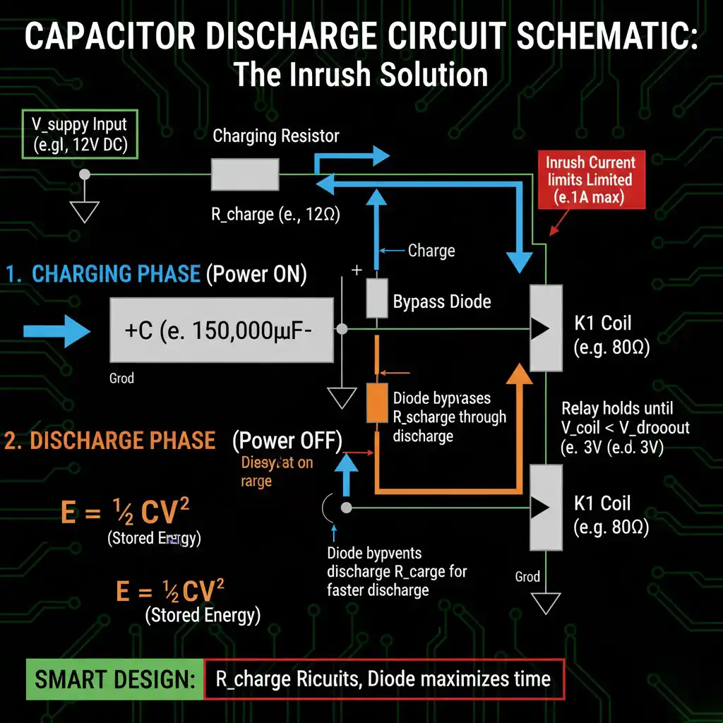
চার্জিং ফেজ: গোস্ট পাওয়ার সঞ্চয় করা
যখন একটি true off-delay relay-তে পাওয়ার প্রয়োগ করা হয়, তখন দুটি জিনিস একই সাথে ঘটে: আউটপুট রিলে সক্রিয় হয় (অ্যাপ্লিকেশন অনুসারে কন্টাক্টগুলি বন্ধ বা খোলা), এবং স্টোরেজ ক্যাপাসিটর চার্জিং রেজিস্টরের মাধ্যমে সরবরাহের ভোল্টেজে চার্জ হয়।.
সম্পূর্ণরূপে চার্জ করা ক্যাপাসিটরে সঞ্চিত শক্তি একটি সরল সূত্র অনুসরণ করে:
E = ½CV²
কোথায়:
- E = শক্তি (জুল)
- C = ক্যাপাসিট্যান্স (ফ্যারাড)
- V = ভোল্টেজ (ভোল্ট)
12V-এ চার্জ করা একটি 2200μF ক্যাপাসিটরের জন্য:
E = ½ × 0.0022F × (12V)² = 0.158 জুল
এটি একটি 12V/85Ω রিলে কয়েলকে (পাওয়ার = V²/R = 1.69W) প্রায় 0.094 সেকেন্ডের জন্য সক্রিয় রাখার জন্য যথেষ্ট শক্তি... যদি আপনি এটিকে সম্পূর্ণ পাওয়ারে তাৎক্ষণিকভাবে ডিসচার্জ করেন।.
কিন্তু আপনি তা করেন না। ক্যাপাসিটর ডিসচার্জ হয় ধীরে ধীরে রিলে কয়েল রেজিস্ট্যান্সের মাধ্যমে, এবং সেখানেই টাইমিং ম্যাজিক ঘটে।.
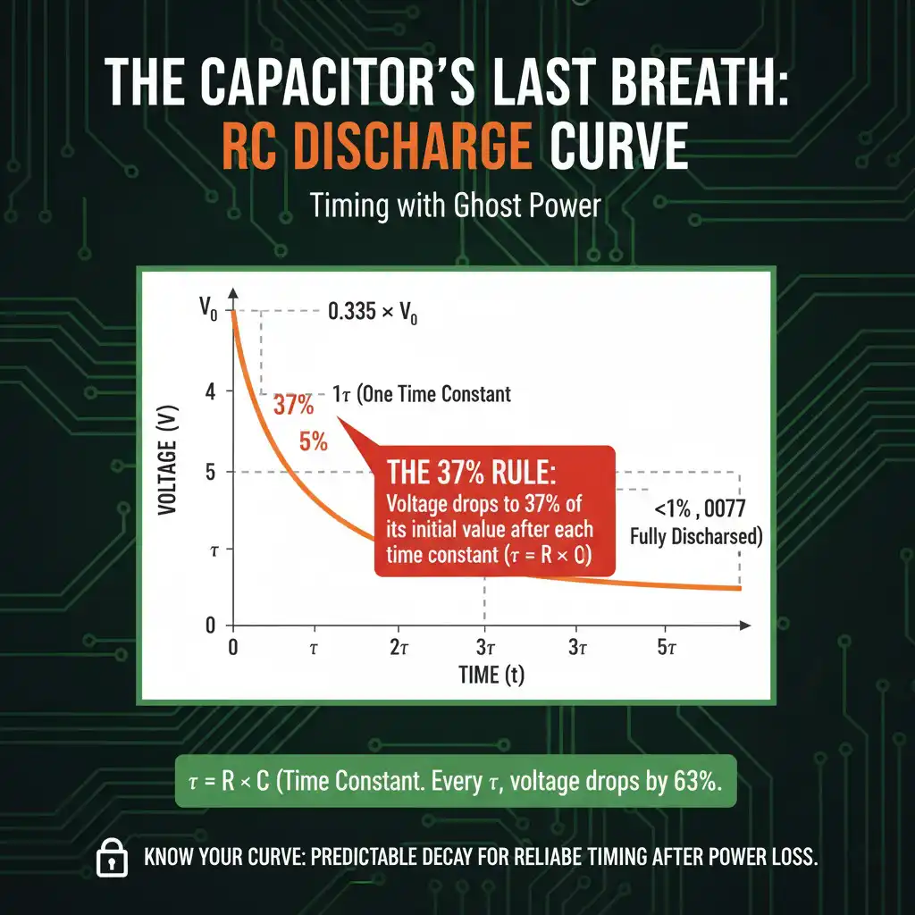
ডিসচার্জ ফেজ: 37% নিয়ম
যখন ইনপুট পাওয়ার সরানো হয়, তখন ক্যাপাসিটর রিলে কয়েল রেজিস্ট্যান্সের মাধ্যমে ডিসচার্জ হতে শুরু করে। ক্যাপাসিটরের ভোল্টেজ রৈখিকভাবে কমে যায় না—এটি একটি সূচকীয় ক্ষয় কার্ভ অনুসরণ করে যা দ্বারা নিয়ন্ত্রিত হয় আরসি টাইম কনস্ট্যান্ট:
τ (টাউ) = R × C
কোথায়:
- τ = টাইম কনস্ট্যান্ট (সেকেন্ড)
- R = রেজিস্ট্যান্স (ওহম)
- C = ক্যাপাসিট্যান্স (ফ্যারাড)
এখানে সুন্দর অংশটি হল: ঠিক একটি টাইম কনস্ট্যান্ট (τ) পরে, ভোল্টেজ অবিকল ক্ষয় হয়ে যাবে তার প্রাথমিক মানের 37%.
40% নয়। 35% নয়। অবিকল 37% (আসলে 36.8%, বা আরও স্পষ্টভাবে, 1/e যেখানে e ≈ 2.718)।.
এটি নির্বিচারে নয়—এটি সূচকীয় ফাংশনে বেক করা হয়েছে যা আরসি ডিসচার্জকে নিয়ন্ত্রণ করে:
V(t) = V₀ × e^(-t/τ)
t = τ-এ: V(τ) = V₀ × e^(-1) = V₀ × 0.368 = V₀-এর 37%
কেন এটি গুরুত্বপূর্ণ: প্রতিটি অতিরিক্ত টাইম কনস্ট্যান্ট ভোল্টেজকে আরও 37% কমিয়ে দেয় অবশিষ্ট ভোল্টেজ।.
- 1τ-এ: 37% অবশিষ্ট (63% ডিসচার্জ)
- 2τ-এ: 13.5% অবশিষ্ট (86.5% ডিসচার্জ হয়েছে)
- 3τ-এ: 5% অবশিষ্ট (95% ডিসচার্জ হয়েছে)
- 5τ-এ: 99% ডিসচার্জ হয়েছে)
আমাদের 85Ω কয়েল এবং 2200μF ক্যাপাসিটর সহ 12V রিলে জন্য:
τ = 85Ω × 0.0022F = 0.187 সেকেন্ড
0.187 সেকেন্ড পরে, ক্যাপাসিটরের ভোল্টেজ (এবং সেইজন্য রিলে কয়েলের ভোল্টেজ) হবে 4.4V। 0.374 সেকেন্ড (2τ) পরে, এটি হবে 1.6V। 0.56 সেকেন্ড (3τ) পরে, মাত্র 0.6V।.
কিন্তু এখানে গুরুত্বপূর্ণ প্রশ্ন হল: কত ভোল্টেজে রিলে কয়েল আসলে রিলিজ করে?
ড্রপআউট কৌশল: কেন বাস্তব সময় গণনা করা সময়ের চেয়ে বেশি হয়
একবার টেনে আনার পরে একটি 12V রিলেকে সক্রিয় রাখতে 12V প্রয়োজন হয় না।.
দ্য পিকআপ ভোল্টেজ (একটি ডি-এনার্জাইজড রিলেকে প্রাথমিকভাবে সক্রিয় করতে প্রয়োজনীয় ভোল্টেজ) সাধারণত রেটেড ভোল্টেজের 75-85% হয়—একটি 12V রিলের জন্য এটিকে 9-10V ধরা হয়। কিন্তু ড্রপআউট ভোল্টেজ (যে ভোল্টেজে একটি ইতিমধ্যে-সক্রিয় রিলে রিলিজ করে) অনেক কম: সাধারণত রেটেড ভোল্টেজের 20-30%, অথবা আমাদের 12V রিলের জন্য 2.4-3.6V।.
এটি চৌম্বকীয় সার্কিটের হিস্টেরেসিসের কারণে ঘটে। যখন রিলে আর্মেচার পোল পিসের সাথে স্পর্শ করে (সম্পূর্ণরূপে সক্রিয় অবস্থান), তখন বাতাসের ব্যবধান শূন্য হয়, চৌম্বকীয় অনিচ্ছা হ্রাস পায় এবং আর্মেচারকে ধরে রাখার জন্য চৌম্বক ক্ষেত্র বজায় রাখতে অনেক কম ম্যাগনেটোমোটিভ ফোর্স (এবং সেইজন্য কম কয়েল কারেন্ট/ভোল্টেজ) প্রয়োজন হয়।.
এর মানে হল আপনার সময় গণনা RC হিসাবের চেয়ে অনেক বেশি হবে।.
আসুন 2.8V (রেটেড ভোল্টেজের 23%) এর ড্রপআউট ভোল্টেজ ধরে নিয়ে আমাদের 12V রিলের (85Ω কয়েল, 2200μF ক্যাপাসিটর) জন্য পুনরায় গণনা করি:
V(t) = V₀ × e^(-t/τ) ব্যবহার করে, যখন V(t) = 2.8V তখন t এর মান বের করুন:
2.8V = 12V × e^(-t/0.187s)
0.233 = e^(-t/0.187s)
ln(0.233) = -t/0.187s
-1.46 = -t/0.187s
t = 0.273 সেকেন্ড
সুতরাং আমাদের 2200μF ক্যাপাসিটর রিলেটিকে 0.273 সেকেন্ডের জন্য সক্রিয় রাখে, যা সরল শক্তি গণনা দ্বারা প্রস্তাবিত <0.1 সেকেন্ড নয়।.
সেটাই হল ড্রপআউট কৌশল বাস্তবে।.
5 সেকেন্ডের হোল্ড-আপ সময় চান? পিছন থেকে কাজ করুন:
t_desired = 5 সেকেন্ড, τ = RC = 0.187s (আগে থেকে)
5 সেকেন্ড কতগুলি টাইম কনস্ট্যান্ট? 5s / 0.187s = 26.7 টাইম কনস্ট্যান্ট
26.7τ-এ, ভোল্টেজ মূলত শূন্য হবে—ড্রপআউটের অনেক নিচে। ভোল্টেজ 2.8V এ পৌঁছালে আমাদের সমাধান করতে হবে:
2.8/12 = 0.233, তাই আমাদের প্রয়োজন: e^(-t/τ) = 0.233
-t/τ = ln(0.233) = -1.46
t = 5s এর জন্য: τ = 5s / 1.46 = 3.42 সেকেন্ড
অতএব: C = τ/R = 3.42s / 85Ω = 0.040F = 40,000μF
12V এ একটি 40,000μF ক্যাপাসিটর? এটি শারীরিকভাবে বড় (প্রায় একটি D-সেল ব্যাটারির আকারের) এবং খরচ $15-25। করা সম্ভব, কিন্তু মার্জিত নয়।.
এই কারণে ল্যাচিং রিলে (পদ্ধতি 2) বা দীর্ঘ সময়কালের জন্য প্রায়শই ছোট ব্যাটারি সহ মাইক্রোপ্রসেসর-ভিত্তিক ডিজাইন ব্যবহার করা হয়—ক্যাপাসিটরের আকার 30-60 সেকেন্ডের বেশি একটানা রিলে ধরে রাখার জন্য অবাস্তব হয়ে যায়।.
আপনার ক্যাপাসিটরের আকার নির্ধারণ: 3-ধাপের পদ্ধতি
আসুন একটি বাস্তব-বিশ্বের নকশা উদাহরণের মাধ্যমে কাজ করি: পাওয়ার অপসারণের পরে আপনার একটি 12V রিলেকে 10 সেকেন্ডের জন্য সক্রিয় রাখতে হবে।.
ধাপ 1: আপনার রিলের স্পেসিফিকেশন জানুন
আপনার যা প্রয়োজন:
- কয়েল ভোল্টেজ: 12V DC
- কয়েল রেজিস্ট্যান্স: একটি মাল্টিমিটার দিয়ে পরিমাপ করুন বা ডেটাশিট দেখুন (ধরা যাক 80Ω)
- ড্রপআউট ভোল্টেজ: হয় অভিজ্ঞতার সাথে পরীক্ষা করুন অথবা রেটেড এর 25% এ অনুমান করুন = 3.0V
যদি আপনার ড্রপআউট ভোল্টেজ না থাকে, তাহলে এটি পরীক্ষা করুন: রিলে কয়েলে রেটেড ভোল্টেজ প্রয়োগ করুন। একবার সক্রিয় হয়ে গেলে, কন্টাক্টগুলি নিরীক্ষণ করার সময় একটি পরিবর্তনশীল পাওয়ার সাপ্লাই দিয়ে ধীরে ধীরে ভোল্টেজ কমান। যে ভোল্টেজে রিলে রিলিজ করে সেটি নোট করুন। সেটাই আপনার ড্রপআউট ভোল্টেজ।.
প্রো-টিপ #1: ড্রপআউট ভোল্টেজ আপনার বন্ধু। বেশিরভাগ রিলে কয়েল রেটেড ভোল্টেজের 20-30% এ ধরে রাখে, যা আপনাকে সরল শক্তি গণনা থেকে 3-5 গুণ বেশি সময় দেয়।.
ধাপ 2: প্রয়োজনীয় ক্যাপাসিট্যান্স গণনা করুন
আগে থেকে প্রাপ্ত ড্রপআউট কৌশল সূত্রটি ব্যবহার করুন:
t = -τ × ln(V_dropout / V_initial)
যেখানে τ = RC, তাই:
t = -RC × ln(V_dropout / V_initial)
C এর জন্য সমাধান করতে পুনর্বিন্যাস করুন:
C = -t / [R × ln(V_dropout / V_initial)]
আমাদের উদাহরণের জন্য:
- t = 10 সেকেন্ড
- R = 80Ω
- V_initial = 12V
- V_dropout = 3.0V
C = -10s / [80Ω × ln(3.0V / 12V)]
C = -10s / [80Ω × ln(0.25)]
C = -10s / [80Ω × (-1.386)]
C = 10s / 110.9
C = 0.090F = 90,000μF
এটাই তাত্ত্বিকভাবে সর্বনিম্ন।.
ধাপ ৩: বাস্তব-বিশ্বের কারণগুলো বিবেচনা করুন
এখানে তত্ত্ব এবং বাস্তবতার মিলন ঘটে। তিনটি বিষয় আপনার সময়কে প্রভাবিত করবে:
ফ্যাক্টর ১: ক্যাপাসিটরের লিকেজ কারেন্ট
বাস্তব ক্যাপাসিটর নিখুঁত অন্তরক নয়। লিকেজ কারেন্ট একটি সমান্তরাল ডিসচার্জ পথ সরবরাহ করে, যা কার্যকরভাবে সময় কমিয়ে দেয়। ইলেক্ট্রোলাইটিক ক্যাপাসিটরের জন্য, লিকেজ রুম তাপমাত্রায় 0.01CV থেকে 0.03CV (μA প্রতি μF-V) হতে পারে।.
আমাদের 90,000μF/12V ক্যাপাসিটরের জন্য: লিকেজ ≈ 0.02 × 90,000μF × 12V = 21,600μA = 21.6mA
ড্রপআউটে রিলে কয়েলের কারেন্টের সাথে তুলনা করুন (3V / 80Ω = 37.5mA)। লিকেজ কারেন্ট রিলে কয়েলের প্রায় অর্ধেক কারেন্ট ব্যবহার করছে!
সমাধান: ক্রিটিক্যাল টাইমিং অ্যাপ্লিকেশনের জন্য লো-লিকেজ ফিল্ম ক্যাপাসিটর (পলিপ্রোপিলিন বা পলিয়েস্টার) ব্যবহার করুন অথবা ইলেক্ট্রোলাইটিকের জন্য 30-50% ক্যাপাসিটেন্স মার্জিন যোগ করুন।.
প্রো-টিপ ১: ক্যাপাসিটর লিকেজ কারেন্ট আপনার সময় চুরি করে। ১০ সেকেন্ডের বেশি ডিলে-র জন্য ফিল্ম ক্যাপাসিটর (পলিপ্রোপিলিন/পলিয়েস্টার) ব্যবহার করুন, ইলেক্ট্রোলাইটিক নয়।.
ফ্যাক্টর ২: তাপমাত্রার প্রভাব
তাপমাত্রা প্রতি ১০°C বৃদ্ধিতে ক্যাপাসিটরের লিকেজ কারেন্ট প্রায় দ্বিগুণ হয়। ২৫°C তাপমাত্রায় ২০mA লিকেজযুক্ত ক্যাপাসিটরের ৩৫°C তাপমাত্রায় ৪০mA এবং ৪৫°C তাপমাত্রায় ৮০mA হতে পারে।.
রিলে ড্রপআউট ভোল্টেজও তাপমাত্রার সাথে পরিবর্তিত হয়—সাধারণত তাপমাত্রা বৃদ্ধির সাথে কয়েলের রেজিস্ট্যান্স সামান্য বৃদ্ধি পায় (তামার পজিটিভ তাপমাত্রা সহগ)। এটি সামান্য সাহায্য করে, তবে ক্যাপাসিটরের লিকেজের ক্ষতিপূরণ দেওয়ার জন্য যথেষ্ট নয়।.
ফ্যাক্টর ৩: ক্যাপাসিটরের সহনশীলতা
ইলেক্ট্রোলাইটিক ক্যাপাসিটরের সাধারণত -২০%/+৮০% সহনশীলতা থাকে। সেই ৯০,০০০μF ক্যাপাসিটরটি আসলে ৭২,০০০μF হতে পারে (-২০% এ)। ফিল্ম ক্যাপাসিটরগুলো আরও টাইট, সাধারণত ±৫-১০%।.
সুরক্ষা মার্জিন প্রয়োগ করুন:
এই কারণগুলো বিবেচনা করে, তাপমাত্রা এবং কম্পোনেন্টের সহনশীলতার কারণে নির্ভরযোগ্য কার্যক্রমের জন্য আপনার হিসাব করা ক্যাপাসিটেন্সকে ১.৫ থেকে ২.০ গুণ করুন:
C_actual = 90,000μF × 1.75 = 157,500μF
একটি স্ট্যান্ডার্ড মানে উন্নীত করুন: 2 × 82,000μF = 164,000μF প্যারালালে, অথবা যদি পাওয়া যায় তবে একটি একক 150,000μF ক্যাপাসিটর ব্যবহার করুন।.
12V-এ, একটি 150,000μF ইলেক্ট্রোলাইটিক ক্যাপাসিটরের আকার প্রায় 35mm ব্যাস × 60mm উচ্চতা, দাম $8-15 এবং এটি প্রায় 10.8 জুল সঞ্চয় করে।.
ইনরাশ কারেন্ট সীমিত করা: চার্জিং রেজিস্টরের কথা ভুলবেন না
আপনি যখন প্রথম পাওয়ার প্রয়োগ করেন, তখন সেই বড় আনচার্জড ক্যাপাসিটরটিকে একটি শর্ট সার্কিটের মতো দেখায়। শূন্য রেজিস্ট্যান্সের মাধ্যমে 0V থেকে 12V-এ চার্জ হওয়া একটি 150,000μF ক্যাপাসিটর তাত্ত্বিকভাবে অসীম কারেন্টের দাবি করবে।.
বাস্তবে, তারের রেজিস্ট্যান্স এবং পাওয়ার সাপ্লাই ইম্পিডেন্স এটিকে সীমিত করে, তবে আপনি প্রথম কয়েক মিলিসেকেন্ডের জন্য 10-50A এর ইনরাশ কারেন্ট দেখতে পাবেন, যা সম্ভবত কন্টাক্ট, ফিউজ বা পাওয়ার সাপ্লাইয়ের ক্ষতি করতে পারে।.
সমাধান: ইনরাশ কারেন্ট সীমিত করতে ক্যাপাসিটরের সাথে সিরিজে একটি চার্জিং রেজিস্টর (R_charge) যোগ করুন, ডিসচার্জের সময় এটিকে বাইপাস করার জন্য একটি সমান্তরাল ডায়োড ব্যবহার করুন:
[পাওয়ার ইন] → [R_charge] → [+ক্যাপাসিটর-] → [রিলে কয়েল] → [গ্রাউন্ড]
ডায়োড ক্যাপাসিটরকে রিলে কয়েলের মাধ্যমে সরাসরি ডিসচার্জ করার অনুমতি দেয় (কোনো সিরিজ রেজিস্ট্যান্স নেই) এবং R_charge এর মাধ্যমে চার্জিং কারেন্টকে বাধ্য করে।.
R_charge এর আকার নির্ধারণ করুন চার্জিং কারেন্টকে একটি যুক্তিসঙ্গত স্তরে (0.5-2A) সীমিত করতে:
R_charge = V_supply / I_charge_max = 12V / 1A = 12Ω
এটি শুধুমাত্র চার্জিংয়ের সময় RC টাইম কনস্ট্যান্টে 12Ω যোগ করে, চার্জের সময়কাল প্রায় 5τ = 5 × (12Ω + 80Ω) × 0.15F = সম্পূর্ণরূপে চার্জ হতে ৬৯ সেকেন্ড পর্যন্ত বাড়িয়ে দেয়.
যদি এটি খুব বেশি হয়, তবে R_charge কমিয়ে দিন তবে উচ্চ ইনরাশ গ্রহণ করুন (যেমন ~2A ইনরাশের জন্য 6Ω, 35-সেকেন্ড চার্জের সময়)। এই আপসটি আপনার।.
প্রো-টিপ ২: RC টাইম কনস্ট্যান্ট (τ = RC) শুধুমাত্র শুরু—প্রকৃত হোল্ড-আপ সময় আপনার ক্যাপাসিটর ডিসচার্জ কার্ভের সাথে রিলে কয়েলের রেজিস্ট্যান্সের মিলের উপর নির্ভর করে।.
ক্যাপাসিটর নির্বাচন: কেন আকারের চেয়ে প্রকার গুরুত্বপূর্ণ
আপনি ক্যাপাসিটেন্স হিসাব করেছেন। এখন আপনাকে আসল কম্পোনেন্টটি নির্বাচন করতে হবে। ক্যাপাসিটরের রসায়ন টাইমিং অ্যাপ্লিকেশনে কর্মক্ষমতাকে নাটকীয়ভাবে প্রভাবিত করে—আকার সবকিছু নয়।.
ফিল্ম ক্যাপাসিটর বনাম ইলেক্ট্রোলাইটিক: লিকেজ যুদ্ধ
ইলেক্ট্রোলাইটিক ক্যাপাসিটর (অ্যালুমিনিয়াম বা ট্যানটালাম):
সুবিধাদি:
- প্রতি ইউনিট আয়তনে সর্বোচ্চ ক্যাপাসিটেন্স (বড় মানের জন্য গুরুত্বপূর্ণ)
- প্রতি মাইক্রোফারডে কম খরচ ($0.05-0.15 প্রতি 1000μF)
- উচ্চ ভোল্টেজে সহজে পাওয়া যায়
অসুবিধা:
- উচ্চ লিকেজ কারেন্ট (0.01-0.03 CV স্পেক, বাস্তবে আরও খারাপ)
- পোলারিটি-সংবেদনশীল (বিপরীত ভোল্টেজ = তাৎক্ষণিক মৃত্যু)
- সীমিত জীবনকাল (5-10 বছরে ইলেক্ট্রোলাইট শুকিয়ে যায়)
- তাপমাত্রা-সংবেদনশীল ক্যাপাসিটেন্স এবং লিকেজ
এর জন্য সেরা: টাইমিং ডিলে <30 সেকেন্ড যেখানে আকার এবং খরচ প্রধান, অথবা যেখানে আপনি লিকেজের জন্য 1.5-2x মার্জিন যোগ করেছেন।.
ফিল্ম ক্যাপাসিটর (পলিপ্রোপিলিন, পলিয়েস্টার, পলিকார்பোনেট):
সুবিধাদি:
- খুব কম লিকেজ কারেন্ট (<0.001 CV, প্রায়শই ইলেক্ট্রোলাইটিকের চেয়ে 10-100 গুণ কম)
- চমৎকার তাপমাত্রা স্থিতিশীলতা
- দীর্ঘ জীবনকাল (20+ বছর)
- কোনো পোলারিটি বিধিনিষেধ নেই (AC বা বিপরীত DC পরিচালনা করতে পারে)
অসুবিধা:
- একই ক্যাপাসিটেন্সের জন্য অনেক বড় শারীরিক আকার
- বেশি খরচ ($0.50-2.00 প্রতি 1000μF)
- কম ক্যাপাসিটেন্স মানের মধ্যে সীমাবদ্ধ (বাস্তবিকভাবে যুক্তিসঙ্গত আকারের জন্য <50μF)
এর জন্য সেরা: প্রিসিশন টাইমিং >30 সেকেন্ড, উচ্চ-তাপমাত্রার পরিবেশ, অথবা যে অ্যাপ্লিকেশনগুলোতে দীর্ঘমেয়াদী ড্রিফট অগ্রহণযোগ্য।.
হাইব্রিড পদ্ধতি: উভয়ের সেরাটা
30-60 সেকেন্ডের মধ্যে টাইমিংয়ের জন্য, বিবেচনা করুন সমান্তরাল সংমিশ্রণ:
- বাল্ক শক্তি সঞ্চয়ের জন্য বড় ইলেক্ট্রোলাইটিক (হিসাবকৃত ক্যাপাসিটেন্সের ৮০%)
- কম-লিকেজ প্রিসিশনের জন্য ছোট ফিল্ম ক্যাপাসিটর (হিসাবকৃত ক্যাপাসিটেন্সের ২০%)
উদাহরণ: 120,000μF ইলেক্ট্রোলাইটিক + 30,000μF ফিল্ম = 150,000μF মোট
ফিল্ম ক্যাপ ইলেক্ট্রোলাইটিক লিকেজের ক্ষতিপূরণ করে, তাত্ত্বিক হিসাবের কাছাকাছি টাইমিং বাড়ায়। খরচ বৃদ্ধি মাঝারি (~পুরোপুরি ইলেক্ট্রোলাইটিকের চেয়ে প্রায় ৩০% বেশি), তবে টাইমিংয়ের নির্ভুলতা উল্লেখযোগ্যভাবে উন্নত হয়।.
সাধারণ ভুল এবং সমাধান
ভুল ১: সরবরাহের ভোল্টেজের নিচে রেটিংযুক্ত ক্যাপাসিটর ব্যবহার করা
নির্ভরযোগ্যতার জন্য 12V সরবরাহের জন্য 16V-রেটেড (বা উচ্চতর) ক্যাপাসিটর প্রয়োজন। ভোল্টেজ ট্রানজিয়েন্ট, রিপল এবং কম্পোনেন্ট টলারেন্সের কারণে একটি “12V সিস্টেম” কিছু পরিস্থিতিতে 14-15V দেখতে পারে। ক্যাপাসিটরকে তার ভোল্টেজ রেটিংয়ের কাছাকাছি চালালে ব্যর্থতা ত্বরান্বিত হয় এবং লিকেজ বৃদ্ধি পায়।.
সমাধান: কমপক্ষে 1.3x সরবরাহ ভোল্টেজের রেটিংযুক্ত ক্যাপাসিটর ব্যবহার করুন (12V সিস্টেমের জন্য 16V, 18V এর জন্য 25V, ইত্যাদি)।
ভুল #2: ESR (ইকুইভ্যালেন্ট সিরিজ রেজিস্ট্যান্স) উপেক্ষা করা
ক্যাপাসিটরের অভ্যন্তরীণ রেজিস্ট্যান্স (ESR) থাকে যা আদর্শ ক্যাপাসিট্যান্সের সাথে সিরিজে প্রদর্শিত হয়। উচ্চ ESR উপলব্ধ ডিসচার্জ কারেন্ট হ্রাস করে এবং লোডের অধীনে ভোল্টেজ ড্রপ তৈরি করে, যা কার্যকরভাবে হোল্ড-আপ সময় কমিয়ে দেয়।.
বড় ইলেক্ট্রোলাইটিক্সের ESR 0.1-1Ω হতে পারে। ড্রপআউটে 150mA কারেন্ট গ্রহণকারী একটি রিলে কয়েলের জন্য, 1Ω ESR মানে অভ্যন্তরীণ রেজিস্ট্যান্সের কারণে 0.15V ক্ষতি—যা আপনার মার্জিন কমাতে যথেষ্ট।.
সমাধান: ESR স্পেসিফিকেশন পরীক্ষা করুন। টাইমিং অ্যাপ্লিকেশনের জন্য, কম-ESR প্রকারগুলি (0.1Ω বা তার কম) পছন্দ করুন।.
ভুল #3: কারেন্ট ব্যালেন্সিং ছাড়া প্যারালাল সংযোগ
একাধিক ক্যাপাসিটরকে প্যারালালে সংযুক্ত করা (যেমন, একটি 40,000μF এর পরিবর্তে চারটি 10,000μF ক্যাপ) তাত্ত্বিকভাবে দারুণ কাজ করে কিন্তু ক্যাপাসিটরগুলির ESR বা লিকেজ অমিল থাকলে সমস্যা সৃষ্টি করতে পারে। “ভাল” ক্যাপাসিটরটি বেশি কাজ করে, দ্রুত বুড়ো হয় এবং প্রথমে ব্যর্থ হয়—তখন অবশিষ্ট ক্যাপগুলি হঠাৎ করে ছোট হয়ে যায়।.
সমাধান: প্যারালাল করার সময় একই ম্যানুফ্যাকচারিং ব্যাচের মিলিত ক্যাপাসিটর ব্যবহার করুন। কারেন্ট শেয়ারিং বাধ্য করতে প্রতিটি ক্যাপাসিটরের সাথে ছোট সিরিজ রেজিস্টর (0.1-0.5Ω) যোগ করুন।.
প্রো-টিপ #4: ল্যাচিং রিলে কৌশলটি ক্রমাগত পাওয়ার ব্যবহারের পরিবর্তে মেকানিক্যাল মেমরি ব্যবহার করে একই টাইমিংয়ের জন্য 1/10 তম ক্যাপাসিটরের আকার দেয়।.

ঘোস্ট পাওয়ার টাইমার: পাওয়ার লস থেকে বেঁচে থাকা টাইমিং
সত্যিকারের অফ-ডিলে রিলে একটি মৌলিক প্যারাডক্স সমাধান করে: ঘড়ির পাওয়ার উৎস অদৃশ্য হয়ে গেলে আপনি কীভাবে সময় পরিমাপ করবেন?
উত্তরটি বাস করে ক্যাপাসিটরের শেষ নিঃশ্বাসে—সংরক্ষিত বৈদ্যুতিক শক্তি যা ধীরে ধীরে নির্গত হয়, ইনপুট পাওয়ার অদৃশ্য হওয়ার পরে সেকেন্ড বা মিনিটের জন্য রিলে কয়েল এবং টাইমিং সার্কিটগুলিকে শক্তি সরবরাহ করে। এটি ঘোস্ট পাওয়ার: শূন্য হওয়ার আগে শেষ কাজটি সম্পন্ন করার জন্য যথেষ্ট রস।.
তিনটি পদ্ধতি এটি অর্জন করে:
- ক্যাপাসিটর ডিসচার্জ (সবচেয়ে সাধারণ)—RC টাইম কনস্ট্যান্টগুলি শক্তি সঞ্চয়কে সুনির্দিষ্ট টাইমিংয়ে পরিণত করে
- ল্যাচিং রিলে + ছোট ক্যাপাসিটর (সবচেয়ে দক্ষ)—মেকানিক্যাল মেমরির জন্য শুধুমাত্র পালস শক্তির প্রয়োজন
- ছোট ব্যাটারি ব্যাকআপ (দীর্ঘতম হোল্ড-আপ)—মাইক্রোঅ্যাম্প খরচ ঘণ্টার পর ঘণ্টা টাইমিং সক্ষম করে
পদার্থবিদ্যা মার্জিত: 37% নিয়ম এক্সপোনেনশিয়াল RC ডিসচার্জ পরিচালনা করে, কিন্তু ড্রপআউট কৌশল রিলে হিস্টেরেসিস ব্যবহার করে সরল হিসাবের চেয়ে 3-5 গুণ বেশি ব্যবহারিক টাইমিং প্রসারিত করে।.
একটি $2 ফিল্ম ক্যাপাসিটর এবং একটি $5 রিলে একবার $200 নিউম্যাটিক টাইমারের প্রয়োজনীয়তা পূরণ করতে পারে—যা ছোট, সস্তা, আরও নির্ভরযোগ্য এবং ক্ষেত্র-সমন্বয়যোগ্য।.
আধুনিক কন্ট্রোল সিস্টেমগুলিতে পাওয়ার ইন্টারাপশন থেকে বেঁচে থাকা টাইমিং প্রয়োজন। কুলিং ফ্যানগুলি বিয়ারিংয়ের ক্ষতি প্রতিরোধ করে, প্রসেস ভালভগুলি শাটডাউন সিকোয়েন্স সম্পন্ন করে, বা সুরক্ষা সার্কিটগুলি ট্রানজিয়েন্টের সময় সুরক্ষা বজায় রাখে, স্ট্যান্ডার্ড ইলেকট্রনিক্স ব্যর্থ হলে সত্যিকারের অফ-ডিলে রিলে টাইমিং বীমা সরবরাহ করে।.
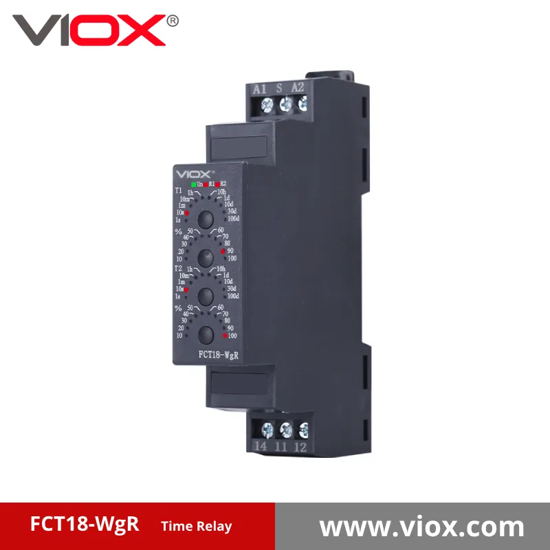
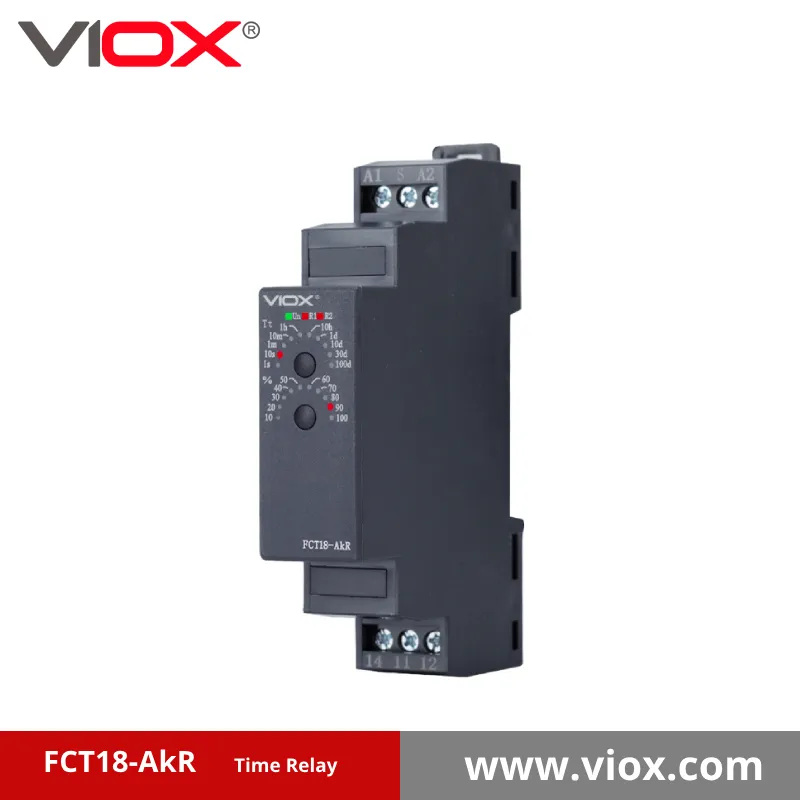
VIOX ELECTRIC ক্যাপাসিটর-ভিত্তিক শক্তি সঞ্চয় সহ সত্যিকারের অফ-ডিলে মডেল সহ ইলেকট্রনিক টাইমিং রিলের একটি সম্পূর্ণ পরিসর সরবরাহ করে, যা মোটর কন্ট্রোল, প্রসেস অটোমেশন এবং সুরক্ষা অ্যাপ্লিকেশনগুলির জন্য উপযুক্ত। আমাদের টাইমিং রিলেগুলি IEC 61810 মান পূরণ করে এবং শিল্প তাপমাত্রা পরিসীমা (-25°C থেকে +70°C পরিবেষ্টিত) জুড়ে নির্ভরযোগ্য অপারেশন সরবরাহ করে।.
প্রযুক্তিগত স্পেসিফিকেশন এবং নির্বাচনGuidance এর জন্য, আমাদের অ্যাপ্লিকেশন ইঞ্জিনিয়ারিং টিমের সাথে যোগাযোগ করুন। আমরা আপনার অ্যাপ্লিকেশনের জন্য সঠিক টাইমিং সমাধান নির্বাচন করতে আপনাকে সাহায্য করব—আমাদের প্রান্তে কোনো ঘোস্ট পাওয়ারের প্রয়োজন নেই।.
