
تعارف: وہ کلک جو کبھی نہیں آئی
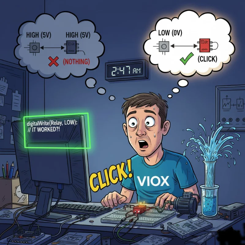
رات 2:47 بجے۔ آپ اس کام میں تین گھنٹے سے لگے ہوئے ہیں۔.
آپ کا Arduino پروجیکٹ بالکل ٹھیک لگ رہا ہے۔ ریلے ماڈیول آپ کے بریڈ بورڈ پر وہیں رکھا ہوا ہے، بالکل اسی طرح وائر کیا گیا ہے جیسے ٹیوٹوریل میں دکھایا گیا تھا۔ آپ نے تین بار چیک کیا ہے: VCC سے 5V، GND سے GND، IN1 سے ڈیجیٹل پن 7۔ کوڈ کمپائل ہوتا ہے۔ آپ اسے اپ لوڈ کرتے ہیں۔ پن 7 HIGH ہو جاتا ہے۔.
کچھ بھی نہیں۔.
کوئی کلک نہیں۔ کوئی ایل ای ڈی نہیں۔ ریلے بس… وہیں بیٹھا ہے۔ آپ کا مذاق اڑاتا ہوا۔.
آپ ریلے ماڈیول بدل دیتے ہیں۔ پھر بھی کچھ نہیں۔ آپ ایک مختلف Arduino پن آزماتے ہیں۔ نہیں۔ آپ کوڈ کو دوبارہ لکھتے ہیں تاکہ بالکل یقینی ہو جائے کہ آپ پن کو HIGH پر سیٹ کر رہے ہیں۔ یہ تصدیق کرتا ہے: HIGH۔ 5 وولٹ۔ ملٹی میٹر بھی اس سے متفق ہے۔.
اور ریلے پھر بھی ٹرگر نہیں ہوگا۔.
پھر، مایوسی یا کیفین سے پیدا ہونے والی تجسس کی وجہ سے، آپ کوڈ کی ایک لائن تبدیل کرتے ہیں:
digitalWrite(relayPin, LOW); // HIGH سے تبدیل کیا گیاکلک۔.
ریلے منسلک ہو جاتا ہے۔ ایل ای ڈی روشن ہو جاتی ہے۔ آپ کا پمپ چلنا شروع ہو جاتا ہے۔ سب کچھ کام کرتا ہے۔.
انتظار کریں… کیا؟ ریلے اس وقت ٹرگر ہوتا ہے جب آپ پن کو HIGH کے بجائے LOW پر سیٹ کرتے ہیں؟ یہ الٹا ہے۔ یہ غلط ہے۔ یہ—
دراصل، یہ بالکل اسی طرح ہے جیسے لو لیول ٹرگر ریلے کام کرتے ہیں۔ اور ایک بار جب آپ سمجھ جائیں کہ کیوں، تو آپ کو احساس ہوگا کہ وہ عجیب نہیں ہیں—وہ دراصل ایک بہتر ڈیزائن ہیں۔.
مجھے وضاحت کرنے دیں۔.
“لو لیول ٹرگر” کا اصل مطلب کیا ہے (آسان انگریزی میں)
ایک لو لیول ٹرگر ریلے اس وقت فعال ہوتا ہے جب اس کے کنٹرول پن کو HIGH سگنل (5V) کے بجائے LOW سگنل (0V/GND) ملتا ہے۔.
ڈیجیٹل منطق کی اصطلاحات میں:
- LOW سگنل (0V) = ریلے آن
- HIGH سگنل (5V) = ریلے آف
اسے ایکٹیو-لو لاجک یا انورس لاجک بھی کہا جاتا ہے۔.
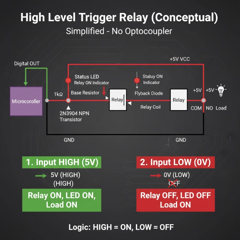
اس کا موازنہ ہائی لیول ٹرگر ریلے سے کریں:
- HIGH سگنل (5V) = ریلے آن
- LOW سگنل (0V) = ریلے آف
بس اتنا ہی ہے۔ یہ بنیادی فرق ہے۔ لیکن یہاں یہ دلچسپ ہو جاتا ہے: ریلے ماڈیول اس بظاہر الٹے طریقے کو کیوں استعمال کریں گے؟
ریلے ماڈیول لو لیول ٹرگرنگ کیوں استعمال کرتے ہیں (راز آپٹوکوپلر ہے)
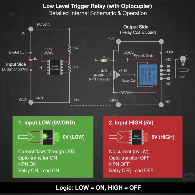
زیادہ تر ریلے ماڈیولز میں صرف ایک ریلے نہیں ہوتی—ان میں ایک مکمل ڈرائیور سرکٹ بنا ہوا ہوتا ہے۔ اس سرکٹ کا دل ایک آپٹوکوپلر (جسے آپٹو-آئسولیٹر بھی کہا جاتا ہے) ہے، عام طور پر ایک PC817 یا اس سے ملتا جلتا۔.
آپٹوکوپلر سرکٹ ڈیزائن
آپ کے ریلے ماڈیول کے اندر اصل میں یہ ہے:
ان پٹ سائیڈ (کنٹرول سگنل):
- آپ کے Arduino کا ڈیجیٹل پن “IN” سے جڑتا ہے”
- IN آپٹوکوپلر کے اندر ایک ایل ای ڈی سے جڑتا ہے (ایک ریزسٹر کے ذریعے)
- ایل ای ڈی کا کیتھوڈ GND سے جڑتا ہے
آؤٹ پٹ سائیڈ (ریلے کوائل):
- ایک فوٹو ٹرانزسٹر (آپٹوکوپلر کے اندر) ایل ای ڈی کی روشنی کا پتہ لگاتا ہے
- یہ ٹرانزسٹر ایک NPN ٹرانزسٹر (جیسے 2N3904) چلاتا ہے
- NPN ٹرانزسٹر ریلے کوائل کو توانائی دیتا ہے
اہم تفصیل: آپٹوکوپلر کی ایل ای ڈی VCC اور IN پن کے درمیان وائرڈ ہے۔ یہ لو-لیول ٹرگرنگ کو سمجھنے کی کلید ہے۔.
لو لیول ٹرگرنگ کیسے کام کرتی ہے
جب IN پن = HIGH (5V):
- ایل ای ڈی کے پار وولٹیج کا فرق = 5V – 5V = 0V
- ایل ای ڈی کے ذریعے کوئی کرنٹ نہیں بہتا
- ایل ای ڈی بند رہتی ہے
- فوٹو ٹرانزسٹر بند رہتا ہے
- ریلے کوائل کو کوئی طاقت نہیں ملتی
- ریلے بند رہتی ہے
جب IN پن = LOW (0V/GND):
- ایل ای ڈی کے پار وولٹیج کا فرق = 5V – 0V = 5V
- ایل ای ڈی کے ذریعے کرنٹ بہتا ہے (ریزسٹر کے ذریعے محدود)
- ایل ای ڈی روشن ہو جاتی ہے
- فوٹو ٹرانزسٹر آن ہو جاتا ہے
- NPN ٹرانزسٹر کنڈکٹ کرتا ہے
- ریلے کوائل توانائی حاصل کرتا ہے
- ریلے آن ہو جاتی ہے
“آہا لمحہ”: سرکٹ VCC سے GND تک IN پن کے ذریعے کرنٹ کھینچتا ہے۔ جب آپ کا Arduino پن LOW ہوتا ہے، تو یہ گراؤنڈ تک ایک راستہ فراہم کرتا ہے، سرکٹ کو مکمل کرتا ہے۔ جب HIGH ہوتا ہے، تو کوئی وولٹیج کا فرق نہیں ہوتا، اس لیے کوئی کرنٹ نہیں بہتا۔.
یہ ڈیزائن دراصل شاندار کیوں ہے
- فیل-سیف رویہ: اگر آپ کی کنٹرول وائر ٹوٹ جاتی ہے یا منقطع ہو جاتی ہے، تو IN پن مؤثر طریقے سے HIGH فلوٹ کرتا ہے (ریزسٹر نیٹ ورک کے ذریعے اندرونی طور پر اوپر کھینچا جاتا ہے)۔ یہ ریلے کو ڈیفالٹ طور پر بند رکھتا ہے—غلطی سے آن ہونے سے زیادہ محفوظ۔.
- فلوٹنگ پنوں کے خلاف تحفظ: Arduino بوٹ اپ کے دوران، پنیں چند ملی سیکنڈ کے لیے ایک غیر متعین حالت میں ہوتی ہیں۔ لو-لیول ٹرگر کے ساتھ، اس کے نتیجے میں عام طور پر ریلے آف (محفوظ) ہوتا ہے بجائے ریلے آن (اعلی طاقت والے بوجھ کے لیے ممکنہ طور پر خطرناک)۔.
- مائیکرو کنٹرولر سے کم کرنٹ ڈرا: جب ریلے آف ہوتی ہے (بہت سے ایپلی کیشنز کے لیے آپ کی سب سے عام حالت)، تو مائیکرو کنٹرولر پن HIGH ہوتا ہے اور تقریباً صفر کرنٹ سورس کرتا ہے۔ جب آپ کو ریلے کو فعال کرنے کی ضرورت ہوتی ہے، تو پن LOW ہو جاتا ہے اور کرنٹ سنک کرتا ہے—جسے مائیکرو کنٹرولر پن عام طور پر سورس کرنے سے بہتر طریقے سے سنبھالتے ہیں۔.
- 3.3V مطابقت: ESP32 اور اسی طرح کے 3.3V آلات ہائی-لیول کنفیگریشن میں 5V ریلے ماڈیولز کو قابل اعتماد طریقے سے چلانے کے لیے جدوجہد کرتے ہیں۔ لیکن لو-لیول موڈ میں، 3.3V پن گراؤنڈ پر کرنٹ کو ٹھیک طرح سے سنک کر سکتا ہے، یہاں تک کہ جب VCC 5V ہو۔ یہ لو-لیول ٹرگر ماڈیولز کو زیادہ عالمگیر طور پر مطابقت پذیر بناتا ہے۔.
پرو ٹپ: یہی وجہ ہے کہ زیادہ تر تجارتی ریلے ماڈیولز ڈیفالٹ طور پر لو-لیول ٹرگر پر ہوتے ہیں—یہ زیادہ مضبوط، مطابقت پذیر اور فیل-سیف ڈیزائن ہے۔.
لو لیول ٹرگر ریلے کو کیسے وائر کریں (مرحلہ وار)
آرڈوینو اونو کے لیے بنیادی وائرنگ (5V لاجک)
پاور کنکشنز:
- ریلے VCC → آرڈوینو 5V
- ریلے GND → آرڈوینو GND
کنٹرول سگنل:
- ریلے IN → آرڈوینو ڈیجیٹل پن (مثال کے طور پر، پن 7)
کوڈ مثال:
const int relayPin = 7;کیا ہو رہا ہے:
- HIGH (5V) ریلے کو آف رکھتا ہے
- LOW (0V) ریلے کو آن کرتا ہے
ESP32 کے لیے وائرنگ (3.3V لاجک)
ESP32 ہائی پر 3.3V آؤٹ پٹ کرتا ہے، جو کچھ 5V ریلے ماڈیولز کے ساتھ مسائل پیدا کر سکتا ہے۔ یہاں قابل اعتماد طریقہ ہے:
پاور کنکشنز:
- ریلے VCC → بیرونی 5V سپلائی (یا ESP32 کی 5V پن اگر USB پاور استعمال کر رہے ہیں)
- ریلے GND → ESP32 کے ساتھ مشترکہ گراؤنڈ
کنٹرول سگنل:
- ریلے IN → ESP32 GPIO پن (مثال کے طور پر، GPIO 23)
کوڈ مثال:
const int relayPin = 23; // ESP32 GPIO23یہ 3.3V کے ساتھ کیسے کام کرتا ہے:
جب ESP32 پن LOW (0V) ہو جاتا ہے، تو یہ گراؤنڈ پاتھ فراہم کرتا ہے۔ آپٹوکوپلر کی LED کو 5V VCC سپلائی سے پاور ملتی ہے، اس لیے پوری 5V وولٹیج ڈراپ LED پر ہوتی ہے—اسے روشن کرنے اور ریلے کو متحرک کرنے کے لیے کافی ہے۔.
پرو ٹپ: اگر آپ کے ریلے ماڈیول میں JD-VCC (ریلے پاور) کے لیے VCC (لاجک پاور) سے الگ جمپر ہے، تو جمپر کو ہٹا دیں اور JD-VCC کو 5V سے پاور دیں جبکہ VCC کو 3.3V پر رکھیں۔ یہ 3.3V مائیکرو کنٹرولرز کے ساتھ مکمل تنہائی اور بہتر وشوسنییتا فراہم کرتا ہے۔.
لو لیول بمقابلہ ہائی لیول: آپ کو کون سا انتخاب کرنا چاہیے؟
زیادہ تر ریلے ماڈیولز لو لیول اور ہائی لیول ٹرگر موڈ کے درمیان انتخاب کرنے کے لیے جمپر یا سوئچ کے ساتھ آتے ہیں۔ یہاں ہر ایک کو استعمال کرنے کا طریقہ بتایا گیا ہے:
لو لیول ٹرگر کب منتخب کریں:
- ✅ 3.3V مائیکرو کنٹرولرز کا استعمال کرتے وقت (ESP32, ESP8266, Raspberry Pi)
- ✅ آپ فیل-سیف رویہ چاہتے ہیں (کنٹرول وائر فیل ہونے پر ریلے ڈیفالٹ طور پر آف ہو جاتی ہے)
- ✅ نامعلوم یا غیر آزمائشی ریلے ماڈیولز کے ساتھ کام کرتے وقت (یہ زیادہ عام/مطابقت پذیر موڈ ہے)
- ✅ آپ کی ایپلیکیشن کو زیادہ تر وقت لوڈ آف رکھنے کی ضرورت ہوتی ہے
- ✅ آپ ابتدائی ہیں (مطابقت کے مسائل کا امکان کم ہے)
درخواستوں کی مثال:
- ہوم آٹومیشن (لائٹس ڈیفالٹ طور پر آف)
- الارم سسٹم (سائرن ڈیفالٹ طور پر آف)
- پمپ کنٹرولز (پمپ آف جب تک کہ فعال طور پر متحرک نہ ہو)
- حفاظتی انٹر لاکس (آلات غیر فعال جب تک کہ فعال طور پر فعال نہ ہو)
ہائی لیول ٹرگر کب منتخب کریں:
- ✅ آپ کو آرڈوینو ری سیٹ/بوٹ کے دوران ریلے آن کرنے کی ضرورت ہے (نایاب لیکن مخصوص استعمال کے معاملات)
- ✅ عام طور پر بند (NC) لوڈز کے ساتھ کام کرتے وقت جہاں آپ الٹا رویہ چاہتے ہیں
- ✅ آپ کے کوڈ لاجک “HIGH = ON” کے ساتھ آسان ہے (ذاتی ترجیح)
- ✅ فعال-ہائی کنٹرول سسٹم کے ساتھ انٹرفیسنگ (PLCs، صنعتی کنٹرولرز)
درخواستوں کی مثال:
- ایمرجنسی لائٹنگ (پاور فیل ہونے کے دوران آن رہیں)
- کولنگ فینز (حفاظت کے لیے ڈیفالٹ طور پر آن)
- بیٹری ڈس کنیکٹ سسٹم (مخصوص فیل-سیف ضروریات)
ایماندارانہ سچائی: آرڈوینو/ESP32 پروجیکٹس کے 95% کے لیے، لو لیول ٹرگر ایک بہتر انتخاب ہے۔.
یہ زیادہ مطابقت پذیر، زیادہ قابل اعتماد اور محفوظ ہے۔ اس کے بارے میں زیادہ نہ سوچیں۔.
عام غلطیاں اور ان کو ٹھیک کرنے کا طریقہ
غلطی 1: “میری ریلے ہمیشہ آن رہتی ہے!”
علامت: آپ کے کوڈ چلنے سے پہلے ہی، آرڈوینو کو پاور دیتے ہی ریلے آن ہو جاتی ہے۔.
وجہ: بوٹ کے دوران، آرڈوینو پن غیر متعینہ (فلوٹنگ) حالت میں ہوتے ہیں۔ اگر پن LOW فلوٹ کرتا ہے، تو ریلے متحرک ہو جاتی ہے۔.
حل:
void setup() {پن کو OUTPUT کے طور پر سیٹ کرنے سے پہلے اس کی حالت سیٹ کرنے سے یہ یقینی ہوتا ہے کہ یہ آف حالت میں شروع ہوتا ہے۔.
غلطی 2: “یہ کام کرتا ہے... لیکن پھر بے ترتیب طور پر متحرک ہو جاتا ہے”
علامت: ریلے کبھی کبھار آن ہو جاتی ہے جب اسے نہیں ہونا چاہیے، خاص طور پر لمبی تاروں یا شور والے ماحول میں۔.
وجہ: برقی شور یا فلوٹنگ پن اسٹیٹس۔.
حل 1 – بیرونی پل-اپ ریزسٹر شامل کریں:
IN پن اور VCC کے درمیان 10kΩ ریزسٹر جوڑیں۔ یہ IN کو HIGH (ریلے آف) رکھتا ہے جب آپ کا آرڈوینو اسے فعال طور پر LOW نہیں کر رہا ہوتا ہے۔.
حل 2 – اندرونی پل-اپ کو فعال کریں:
void setup() {غلطی 3: “ESP32 ریلے مستقل طور پر کلک نہیں کرتی”
علامت: ریلے کبھی کام کرتی ہے، کبھی ناکام ہو جاتی ہے۔ ریلے بورڈ پر LED روشن ہوتی ہے لیکن ریلے کلک نہیں کرتی۔.
وجہ: آپٹوکوپلر LED کو قابل اعتماد طریقے سے چلانے کے لیے 3.3V GPIO سے ناکافی کرنٹ۔.
حل – ایک وقف شدہ 3.3V ریلے ماڈیول استعمال کریں:
خاص طور پر 3.3V ٹرگر وولٹیج کے لیے ریٹیڈ ریلے ماڈیولز تلاش کریں (صرف 3.3V مطابقت پذیر نہیں)۔ ان میں کم LED فارورڈ وولٹیج کی ضروریات کے ساتھ آپٹمائزڈ آپٹوکوپلر سرکٹس ہوتے ہیں۔.
یا – ریلے ماڈیول کے VCC کو 5V پر پاور دیں:
اگرچہ ESP32 3.3V ہے، آپ ریلے ماڈیول کے VCC کو 5V سے پاور دے سکتے ہیں (ESP32 کی 5V پن یا بیرونی سپلائی) جبکہ ESP32 GPIO کرنٹ کو GND میں سنک کرتا ہے۔ یہ آپٹوکوپلر کے ذریعے مضبوط LED کرنٹ فراہم کرتا ہے۔.
غلطی 4: “میں نے جمپر غلط سیٹ کیا”
علامت: ریلے کا رویہ آپ کے کوڈ کی توقع کے برعکس ہے۔.
وجہ: ریلے ماڈیول میں جمپر ہائی لیول ٹرگر موڈ پر سیٹ ہے۔.
حل:
سکرو ٹرمینلز کے قریب 3-پن جمپر تلاش کریں، جو عام طور پر اس طرح لیبل لگا ہوتا ہے:
- H (ہائی لیول ٹرگر)
- COM (کامن)
- L (لو لیول ٹرگر)
لو لیول ٹرگر موڈ کے لیے جمپر کو COM اور L سے جوڑنے کے لیے منتقل کریں۔.
اگر کوئی جمپر موجود نہیں ہے: کچھ ریلے ماڈیولز صرف لو لیول پر فکس ہوتے ہیں۔ پروڈکٹ کی تفصیل چیک کریں یا ٹیسٹ کریں: اگر LOW اسے آن کرتا ہے، تو یہ لو لیول ٹرگر ہے۔.
غلطی #5: “ریلے کلک کرتی ہے لیکن لوڈ آن نہیں ہوتا”
علامت: آپ ریلے کی کلک کی آواز سنتے ہیں، ایل ای ڈی روشن ہوتی ہے، لیکن آپ کا لیمپ/موٹر/پمپ ایکٹیویٹ نہیں ہوتا۔.
وجہ: یہ ٹرگر کا مسئلہ نہیں ہے—یہ ہائی وولٹیج سائیڈ پر وائرنگ کا مسئلہ ہے۔.
حل - لوڈ وائرنگ چیک کریں:
COM (کامن) پاور سورس سے جڑتا ہے (مثال کے طور پر، 12V+ یا AC لائن)
NO (نارمل اوپن) لوڈ پازیٹو ٹرمینل سے جڑتا ہے
لوڈ نیگیٹو پاور سورس نیگیٹو پر واپس جاتا ہے
AC لوڈز کے لیے (جیسے لیمپ):
- COM سے AC ہاٹ وائر
- NO سے لیمپ
- لیمپ کا دوسرا ٹرمینل AC نیوٹرل سے
اہم حفاظتی نوٹ:
اگر AC مینز وولٹیج (110V/220V) کے ساتھ کام کر رہے ہیں، تو وائرنگ کرنے سے پہلے بریکر پر پاور آف کر دیں۔ اگر آپ AC وائرنگ کے ساتھ آرام دہ نہیں ہیں، تو کسی مستند الیکٹریشن سے رجوع کریں۔.
عملی اطلاقات: آپ کو لو لیول ٹرگر ریلے کی اصل میں کب ضرورت ہوتی ہے
1. ہوم آٹومیشن پروجیکٹس
منظرنامہ: لیمپ کے لیے ESP32-کنٹرولڈ سمارٹ آؤٹ لیٹ۔.
لو لیول ٹرگر کیوں:
- ESP32 3.3V ہے (بہتر مطابقت)
- لیمپ کو ڈیفالٹ طور پر آف ہونا چاہیے (فیل-سیف)
- WiFi دوبارہ کنیکٹ ہونے کے دوران بے ترتیب ٹرگرز پریشان کن ہوں گے
نفاذ:
const int relayPin = 23;2. گارڈن اریگیشن کنٹرولر
منظرنامہ: گارڈن بیڈز کے لیے Arduino-ٹائمڈ واٹر پمپ۔.
لو لیول ٹرگر کیوں:
- پمپ ڈیفالٹ طور پر آف (اگر Arduino کریش ہو جائے تو سیلاب سے بچاتا ہے)
- آؤٹ ڈور ریلے تک لمبی تاریں (پل-اپ کے ساتھ شور سے استثنیٰ)
- فیل-سیف: ٹوٹی ہوئی تار = کوئی پانی نہیں = پودا زندہ رہتا ہے
نفاذ:
void waterGarden(int minutes) {3. 3D پرنٹر پاور مینجمنٹ
منظرنامہ: پرنٹ جاب سے پہلے خود بخود پرنٹر کو آن کریں، مکمل ہونے پر آف کریں۔.
لو لیول ٹرگر کیوں:
- پرنٹر اس وقت آف ہوتا ہے جب پرنٹنگ نہیں ہو رہی ہوتی (پاور بچاتا ہے، آگ کے خطرے کو کم کرتا ہے)
- OctoPrint (Raspberry Pi) 3.3V GPIO استعمال کرتا ہے
- فیل-سیف: سسٹم کریش = پرنٹر آف رہتا ہے
4. ایکویریم کنٹرولر
منظرنامہ: Arduino کے ساتھ درجہ حرارت پر مبنی ہیٹر کنٹرول۔.
لو لیول ٹرگر کیوں:
- ہیٹر ڈیفالٹ طور پر آف (اگر سینسر فیل ہو جائے تو مچھلی کو زیادہ گرم ہونے سے بچاتا ہے)
- 5V Arduino یا 3.3V ESP32 مطابقت
- متعدد ریلے (لائٹس، فلٹر، ہیٹر) سب کو مربوط فیل-سیف رویے کی ضرورت ہے
اس کا آپ کے اگلے پروجیکٹ کے لیے کیا مطلب ہے
لو لیول ٹرگر ریلے عجیب نہیں ہیں—یہ معیاری ہیں۔ ایک بار جب آپ منطق کو اندرونی کر لیتے ہیں (“LOW = ON, HIGH = OFF”)، تو یہ فطرت ثانیہ بن جاتے ہیں۔ اور فوائد—فیل-سیف رویہ، بہتر مطابقت، شور سے استثنیٰ—انہیں زیادہ تر Arduino اور ESP32 پروجیکٹس کے لیے ایک سمارٹ انتخاب بناتے ہیں۔.
فوری فیصلہ گائیڈ:
لو لیول ٹرگر ریلے استعمال کریں اگر:
- ✅ آپ ESP32، ESP8266، یا کوئی 3.3V مائیکرو کنٹرولر استعمال کر رہے ہیں
- ✅ آپ کا لوڈ ڈیفالٹ طور پر آف ہونا چاہیے (پمپ، ہیٹر، الارم)
- ✅ آپ فیل-سیف رویہ چاہتے ہیں (تار ٹوٹنا = ریلے آف)
- ✅ آپ ایک ابتدائی پروجیکٹ بنا رہے ہیں
- ✅ آپ منطق کی سطحوں سے لڑنے کے بجائے مطابقت کو اہمیت دیتے ہیں
ہائی لیول ٹرگر ریلے استعمال کریں اگر:
- ✅ آپ کی مخصوص ایپلیکیشن کو مائیکرو کنٹرولر بوٹ کے دوران ریلے آن کی ضرورت ہے
- ✅ آپ صنعتی کنٹرول سسٹم (PLCs) کے ساتھ انٹرفیس کر رہے ہیں
- ✅ آپ کے پاس ایک بہت ہی مخصوص وجہ ہے (اور آپ جانتے ہیں کہ یہ کیا ہے)
پرو ٹپ:
ریلے ماڈیولز خریدتے وقت، ان کی تلاش کریں جو جمپر کے ساتھ ہائی اور لو لیول ٹرگرنگ دونوں کو سپورٹ کرتے ہیں۔ یہ آپ کو ہر پروجیکٹ کے لیے بہترین موڈ منتخب کرنے کی لچک فراہم کرتا ہے۔.
صحیح ریلے ماڈیول کا انتخاب
ریلے ماڈیولز کی خریداری کرتے وقت، یہاں چیک کرنے کے لیے کچھ چیزیں ہیں:
Arduino Uno / Mega (5V) کے لیے:
- آپریٹنگ وولٹیج: 5V DC
- ٹرگر وولٹیج: 5V مطابقت پذیر
- ٹرگر کرنٹ: <15mA (Arduino پن زیادہ سے زیادہ 20-40mA سورس کرتے ہیں)
- آپٹوکوپلر آئسولیشن: ہاں (PC817 یا اس سے ملتا جلتا)
ESP32 / ESP8266 (3.3V) کے لیے:
- آپریٹنگ وولٹیج: 5V DC (ریلے کوائل پاور کے لیے)
- ٹرگر وولٹیج: 3.3V مطابقت پذیر یا لو-لیول ٹرگر موڈ
- ٹرگر کرنٹ: <12mA (ESP32 پن زیادہ سے زیادہ 12mA فراہم کرتے ہیں)
- آپٹوکوپلر آئسولیشن: لازمی
- علیحدہ VCC/JD-VCC: ترجیحی
عام خصوصیات:
- کانٹیکٹ ریٹنگ: 10A @ 250VAC یا 10A @ 30VDC (عام)
- چینلز کی تعداد: 1، 2، 4، 8 (آپ کی ضروریات پر مبنی)
- ماؤنٹنگ: آسان وائرنگ کے لیے سکرو ٹرمینلز
- انڈیکیٹرز: پاور اور ریلے اسٹیٹ کے لیے ایل ای ڈی
VIOX Electric آرڈینو، ESP32، اور صنعتی کنٹرول ایپلی کیشنز کے لیے موزوں ریلے ماڈیولز کی ایک مکمل رینج پیش کرتا ہے۔ ہمارے ریلے ماڈیولز میں یہ خصوصیات ہیں:
- لو-لیول ٹرگر ڈیزائن کے ساتھ حقیقی 3.3V/5V مطابقت
- اعلیٰ معیار کی آپٹوکوپلر آئسولیشن (PC817)
- محفوظ وائرنگ کے لیے سکرو ٹرمینل کنکشنز
- ڈوئل-ایل ای ڈی انڈیکیٹرز (پاور + ریلے اسٹیٹ)
- منتخب کرنے کے قابل ٹرگر موڈز (ہائی/لو لیول کے لیے جمپر)
VIOX ریلے ماڈیولز براؤز کریں → یا ایپلیکیشن کے لحاظ سے مخصوص سفارشات کے لیے ہماری تکنیکی ٹیم سے رابطہ کریں۔.
