اس صفحے پر
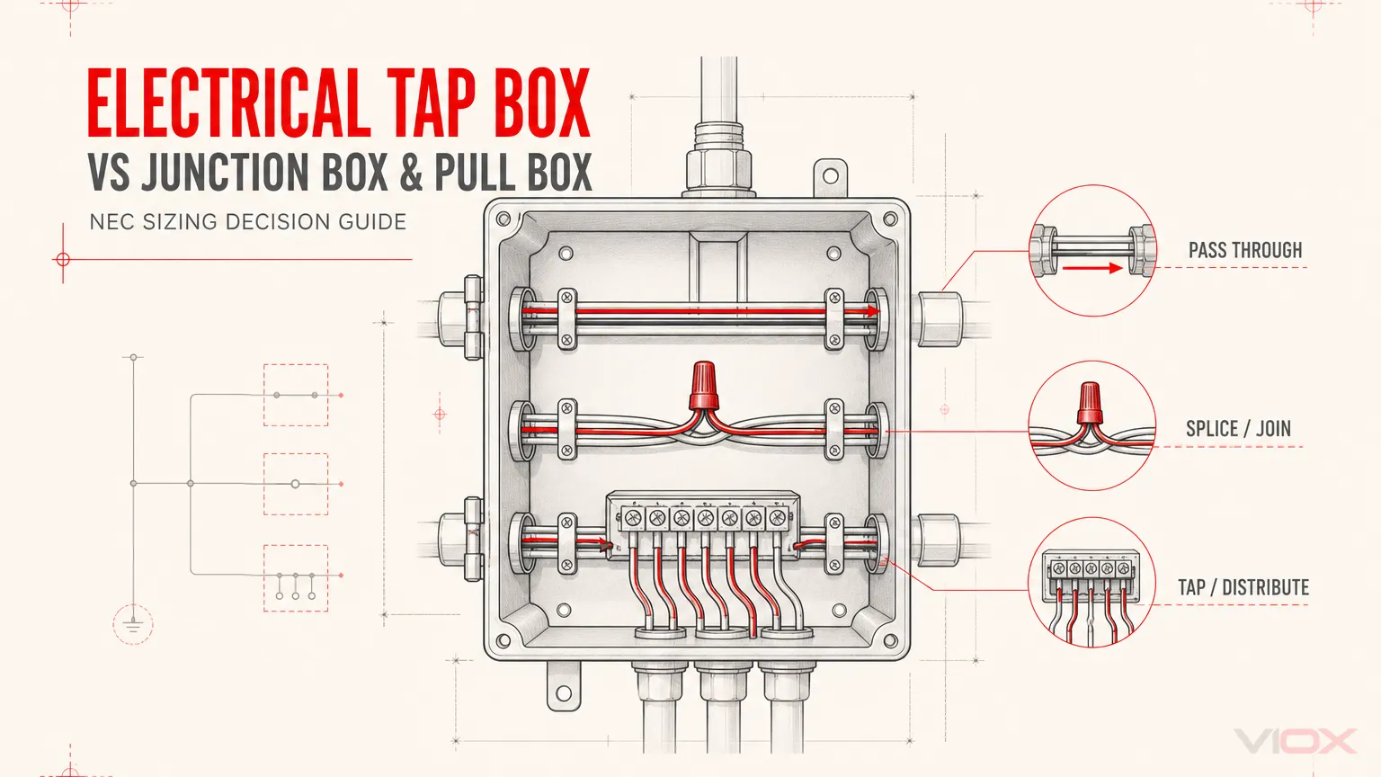
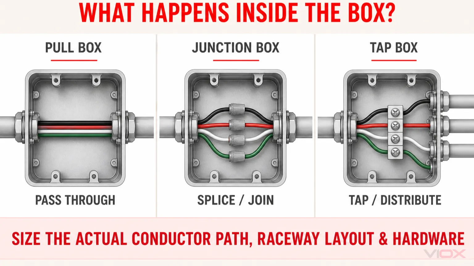
ایک الیکٹریکل ٹیپ باکس ایک ایسا انکلوژر ہے جہاں فیڈر کو ٹیپ کیا جاتا ہے یا اضافی کنڈکٹرز میں تقسیم کیا جاتا ہے، جس کے لیے اکثر لسٹڈ سپلائسنگ کنیکٹرز، ٹرمینل آلات، یا پاور ڈسٹری بیوشن بلاکس کا استعمال کیا جاتا ہے۔ ایک جنکشن باکس ایک وسیع تر اصطلاح ہے جو ایسے انکلوژر کے لیے استعمال ہوتی ہے جس میں کنڈکٹر سپلائسز یا کنکشنز موجود ہوں۔ ایک پل باکس بنیادی طور پر ریس وے سسٹم کے ذریعے کنڈکٹرز کو کھینچنے کے لیے رسائی فراہم کرتا ہے۔.
یہ نام ان کے مطلوبہ کام کی وضاحت کرتے ہیں، لیکن ڈرائنگ پر موجود لیبل خود بخود ضروری نہیں حتمی انکلوژر کے سائز کا تعین نہیں کرتا۔ کنٹرولنگ تقاضوں کا انحصار کنڈکٹر کے سائز، ریس وے لے آؤٹ، اس بات پر ہے کہ آیا کنڈکٹرز کو کھینچا، جوڑا، ٹیپ کیا یا ٹرمینیٹ کیا گیا ہے، نصب شدہ ہارڈویئر، اور مقامی اتھارٹی (AHJ) کی طرف سے اختیار کردہ نیشنل الیکٹریکل کوڈ (NEC) کے ایڈیشن پر ہوتا ہے۔.
فوری فیصلہ سازی کا جدول
| انکلوژر (باکس) کی تفصیل | اندرونی عمل | عام ڈیزائن کا مرکز | NEC کی عام طور پر زیر نظر دفعات* |
|---|---|---|---|
| پل باکس | کنڈکٹرز کا گزرنا؛ باکس پلنگ پوائنٹ فراہم کرتا ہے | ریس وے کی جیومیٹری، کھینچنے کی سمت، کنڈکٹر کا تحفظ، رسائی | 314.28, 314.29 |
| 接线盒 | کنڈکٹرز کو جوڑنا، ملانا، یا سمت تبدیل کرنا | چھوٹے کنڈکٹرز کے لیے باکس فل؛ بڑے کنڈکٹرز کے لیے جیومیٹری اور موڑنے کی جگہ؛ رسائی | 314.16, 314.28, 314.29 |
| ٹیپ باکس | ایک فیڈر یا سرکٹ کو اضافی کنڈکٹرز میں ٹیپ کیا جاتا ہے، اکثر کنیکٹرز یا پاور ڈسٹری بیوشن بلاک کے ذریعے | کنیکٹر کی لسٹنگ، کنڈکٹر کی رینج، انکلوژر کی درجہ بندی، موڑنے کی جگہ، وائرنگ کی جگہ، رسائی | اس میں 312.6، 312.8، 314.28، اور پروڈکٹ لسٹنگ کے تقاضے شامل ہو سکتے ہیں |
قابل اطلاق سیکشن کا انحصار انکلوژر کی قسم اور تنصیب پر ہوتا ہے۔ ہمیشہ اپنائے گئے NEC ایڈیشن، مقامی ترامیم، پروڈکٹ کی ہدایات، اور AHJ کی تشریح کی تصدیق کریں۔.
سب سے اہم اصول: تنصیب کی درجہ بندی کریں، نہ کہ مخفف کی
PB، JB، اور TB ڈرائنگ کے مفید مخففات ہیں، لیکن یہ انجینئرنگ کے جائزے کا متبادل نہیں ہیں۔ انکلوژر منتخب کرنے سے پہلے، پانچ سوالات کے جواب دیں:
- انکلوژر میں سب سے بڑا کنڈکٹر کون سا ہے؟
- کیا کنڈکٹرز سیدھے گزرتے ہیں، مڑتے ہیں، یو-پل (U-pull) بناتے ہیں، سپلائس ہوتے ہیں، ٹیپ ہوتے ہیں، یا ٹرمینیٹ ہوتے ہیں؟
- کون سی ریس ویز (raceways) میں ایک جیسے کنڈکٹرز موجود ہیں؟
- کیا انکلوژر میں لسٹڈ سپلائسنگ کنیکٹرز، ٹرمینلز، یا پاور ڈسٹری بیوشن بلاکس شامل ہوں گے؟
- کیا یہ پروڈکٹ پل/جنکشن باکس ہے، کیبنٹ یا کٹ آؤٹ باکس ہے، یا کسی لسٹڈ آلات کا حصہ ہے؟
یہ ترتیب ایک عام غلطی سے بچاتی ہے: یہ فرض کر لینا کہ سپلائسز والے ہر باکس میں صرف کیوبک انچ باکس-فل کا حساب استعمال ہوتا ہے، جبکہ بغیر سپلائسز والے ہر باکس میں صرف پل-باکس فارمولا استعمال ہوتا ہے۔ بڑے کنڈکٹرز کے لیے، سپلائسز والا جنکشن باکس اب بھی NEC 314.28 کے تحت آ سکتا ہے۔.
دو طرفہ مرکوز موازنہ کے لیے، ملاحظہ کریں پل باکس بمقابلہ جنکشن باکس: اہم فرق اور NEC سائزنگ. رسائی، سپورٹ، کورز، اور آرٹیکل 314 کی عمومی ضروریات کے لیے، الگ گائیڈ استعمال کریں۔ این ای سی (NEC) جنکشن باکس کی ضروریات کی گائیڈ.
الیکٹریکل ٹیپ باکس کیا ہے؟
ٹیپ باکس ایک بند پوائنٹ فراہم کرتا ہے جہاں آنے والے کنڈکٹر یا فیڈر کو ایک یا زیادہ آؤٹ گوئنگ کنڈکٹرز سے جوڑا جاتا ہے۔ سسٹم کے لحاظ سے، ٹیپ ایک لسٹڈ مکینیکل کنیکٹر، کمپریشن کنیکٹر، ٹرمینل اسمبلی، بس اسٹرکچر، یا پاور ڈسٹری بیوشن بلاک (PDB) کے ذریعے بنایا جا سکتا ہے۔.
عام ایپلی کیشنز میں شامل ہیں:
- ایک فیڈر کو کئی پینل بورڈز یا لوڈز میں تقسیم کرنا؛;
- ملٹی ٹیننٹ اور میٹرنگ کے انتظامات؛;
- انڈسٹریل کنٹرول اور پاور ڈسٹری بیوشن سسٹمز؛;
- آلات کی ریٹروفٹنگ جہاں کنڈکٹرز کو قابل رسائی انکلوژر کے اندر برانچ کرنا ضروری ہو؛;
- لسٹڈ ٹرمینل یا ڈسٹری بیوشن ہارڈویئر کا استعمال کرتے ہوئے ماڈیولر ڈسٹری بیوشن سسٹمز۔.
“ٹیپ باکس” ایک فنکشنل انڈسٹری کی اصطلاح ہے، نہ کہ کسی ایک سائزنگ فارمولے کا عالمی شارٹ کٹ۔ فیلڈ میں اسمبل شدہ ٹیپ انکلوژر کو ایک ڈیزائن میں پل یا جنکشن باکس کے طور پر اور دوسرے میں کیبنٹ یا کٹ آؤٹ باکس کے طور پر سمجھا جا سکتا ہے۔ لسٹڈ آلات کی تعمیر اور تنصیب کے تقاضے مختلف ہو سکتے ہیں۔.
ٹیپ باکس بمقابلہ جنکشن باکس بمقابلہ پل باکس
پل باکس کنڈکٹر کو کھینچنے کا ایک پوائنٹ بناتا ہے۔
ایک عام پل باکس میں، کنڈکٹرز مسلسل رہتے ہیں جبکہ انسٹالرز انہیں ایک طویل یا سمت بدلنے والے ریس وے کے ذریعے کھینچتے ہیں۔ انکلوژر کو کنڈکٹرز کو موڑنے کے لیے کافی جگہ فراہم کرنی چاہیے تاکہ انسولیشن کو نقصان نہ پہنچے یا موڑنے اور فاصلے کے قابل اطلاق اصولوں کی خلاف ورزی نہ ہو۔.
لفظ “پل” فنکشن کو بیان کرتا ہے؛ یہ ہر ممکن پل یا جنکشن انکلوژر میں ہر قسم کے اسپلائس (جوڑ) کو منع نہیں کرتا۔ اگر اسپلائسز نصب کیے جاتے ہیں، تو ڈیزائن کا جائزہ ان دفعات کے تحت لیا جانا چاہیے جو اسپلائسز اور اینگل یا یو-پل (U-pull) پر لاگو ہوتی ہیں، بجائے اس کے کہ یہ فرض کر لیا جائے کہ باکس ایک سادہ سیدھا پل کیس ہے۔.
جنکشن باکس اسپلائسز اور کنکشنز کی حفاظت کرتا ہے۔
جنکشن باکس میں برانچ سرکٹ اسپلائسز، فیڈر اسپلائسز، ٹرمینیشنز، یا وائرنگ کے طریقوں کے درمیان ٹرانزیشن شامل ہو سکتے ہیں۔ NEC 314.16 باکس فل طریقہ کار کے تحت عام طور پر کور کیے جانے والے کنڈکٹرز کے لیے، درکار حجم کا انحصار کنڈکٹرز کی تعداد اور سائز، اور آلات، کلیمپس، گراؤنڈنگ کنڈکٹرز، اور دیگر اشیاء پر ہوتا ہے جنہیں اختیار کردہ کوڈ ایڈیشن کے مطابق شمار کیا جاتا ہے۔.
جب کسی باکس میں 4 AWG یا اس سے بڑے کنڈکٹرز موجود ہوں، تو صرف چھوٹے کنڈکٹر والے باکس فل کیلکولیشن پر اکتفا نہ کریں۔ NEC 314.28 ریس وے کی ترتیب، پل ڈائریکشن، اور اسپلائسز کی بنیاد پر کم از کم طول و عرض بھی متعین کر سکتا ہے۔.
ٹیپ باکس ڈسٹری بیوشن ہارڈویئر اور ٹرمینیشن کی حدود میں اضافہ کرتا ہے۔
ٹیپ باکس ایک کنکشن انکلوژر ہے جس میں ایک اضافی ڈیزائن کا مسئلہ ہوتا ہے: ٹیپ ہارڈویئر خود جگہ گھیرتا ہے اور کنڈکٹر کے داخلے، سٹرپ کی لمبائی، ٹارک، فاصلے، اور وائر رینج کی ضروریات قائم کرتا ہے۔ باکس کو کسی فرضی عام بلاک کے بجائے اصل کنیکٹر یا PDB کے مطابق ہونا چاہیے۔.
لہذا انکلوژر کے جائزے میں درج ذیل چیزیں شامل ہونی چاہئیں:
- بلاک یا کنیکٹر کی لسٹنگ اور تنصیب کی ہدایات؛;
- کنڈکٹر کا مجاز مواد، مقدار، اور سائز کی حد؛;
- لائن اور لوڈ کنڈکٹر کی روٹنگ؛;
- ہر ٹرمینل پر موڑنے کی جگہ (بینڈنگ اسپیس)؛;
- انکلوژر کی دیوار اور دیگر لائیو حصوں سے علیحدگی؛;
- تنصیب کا طریقہ اور مکینیکل سپورٹ؛;
- ٹائٹننگ، معائنے، اور مستقبل کی سروس کے لیے رسائی؛;
- مکمل تنصیب کے لیے قابل اطلاق شارٹ سرکٹ کرنٹ ریٹنگ اور اوور کرنٹ پروٹیکشن کی شرائط۔.
VIOX پیشکش کرتا ہے۔ پاور ڈسٹری بیوشن بلاکس پینل اور ڈسٹری بیوشن ایپلی کیشنز کے لیے، لیکن ماڈل کا انتخاب ماڈل کی مخصوص ریٹنگز، کنڈکٹر رینج، تنصیبی ہدایات، اور مکمل اسمبلی کی ضروریات پر مبنی ہونا چاہیے۔.
NEC 314.16 بمقابلہ 314.28: پرانا آرٹیکل کہاں غلط تھا
اس آرٹیکل کے پچھلے ورژن میں فرق کو اس طرح بیان کیا گیا تھا:
پل باکس = NEC 314.28؛ جنکشن باکس = NEC 314.16۔.
یہ شارٹ کٹ نامکمل ہے۔ ایک زیادہ محفوظ فیصلہ کن اصول یہ ہے:
| تنصیب کی شرط | بنیادی حساب کتاب یا جائزہ |
|---|---|
| آؤٹ لیٹ، ڈیوائس، یا جنکشن باکس میں چھوٹے کنڈکٹرز | NEC 314.16 کے تحت باکس فل والیوم، بشمول تمام مطلوبہ الاؤنسز |
| پل یا جنکشن باکس میں 4 AWG یا اس سے بڑے کنڈکٹرز والی ریس ویز یا کیبلز | کنڈکٹر کے راستے اور ریس وے کی ترتیب کی بنیاد پر NEC 314.28 کے تحت کم از کم طول و عرض |
| بڑے کنڈکٹرز کے ساتھ سیدھا کھنچاؤ (Straight pull) | 314.28 سیدھی کھنچائی (straight-pull) کے طول و عرض |
| زاویہ دار کھنچائی (angle pull)، یو-پل (U-pull)، یا بڑے کنڈکٹرز کے ساتھ اسپلائسنگ | 314.28 زاویہ دار/یو-پل/اسپلائس کے طول و عرض اور ریس وے کا درمیانی فاصلہ |
| پل یا جنکشن باکس میں نصب ٹیپ ہارڈویئر | 314.28 کے تقاضے بمعہ لسٹڈ ڈسٹری بیوشن یا اسپلائسنگ ہارڈویئر کے لیے دفعات |
| کیبنٹ یا اسی طرح کے آلات کے انکلوژر میں نصب ٹیپ ہارڈویئر | قابل اطلاق آرٹیکل 312 وائرنگ-اسپیس اور بینڈنگ-اسپیس کی دفعات، آلات کی لسٹنگ، اور مینوفیکچرر کی ہدایات |
سیکشن کا درست سیٹ انکلوژر اور آلات کے لحاظ سے مختلف ہو سکتا ہے۔ اہم تصحیح یہ ہے کہ اسپلائس (splice) کا اضافہ خود بخود NEC 314.28 کو ختم نہیں کرتا۔.
NEC 314.28 اسٹریٹ پل (Straight-Pull) کا اصول
NEC 314.28 کے دائرہ کار میں سیدھے کھنچاؤ (straight pull) کے لیے، کنڈکٹرز ایک دیوار سے داخل ہوتے ہیں اور سمت تبدیل کیے بغیر مخالف دیوار سے باہر نکلتے ہیں۔ کھنچاؤ کی سمت میں باکس کی کم از کم لمبائی یہ ہے:
کم از کم اسٹریٹ پل لمبائی = 8 × سب سے بڑے ریس وے (raceway) کا تجارتی سائزمثال: 3 انچ کا اسٹریٹ پل
اگر سب سے بڑا ریس وے 3 انچ کا ہو:
8 × 3 انچ = 24 انچ.لہذا اس اسٹریٹ پل کی سمت میں کم از کم طول و عرض 24 انچ ہے۔ یہ حساب کتاب ہر مطلوبہ طول و عرض کا تعین نہیں کرتا۔ ڈیزائنر کو اب بھی باقی کنڈکٹر کے راستوں، اندراجات، کورز، رسائی، عملی کھنچاؤ کی جگہ، اور کسی بھی آلات سے متعلق مخصوص تقاضوں کو چیک کرنا ہوگا۔.
NEC 314.28 اینگل پلز، یو-پلز، اور سپلائسز
جب کنڈکٹرز اپنی سمت تبدیل کرتے ہیں، اسی دیوار سے واپس آتے ہیں، یا انہیں جوڑا (splice) جاتا ہے، تو مخالف دیوار کا طول و عرض اس دیوار پر موجود ہر قطار میں ریس ویز (raceways) کی بنیاد پر طے کیا جاتا ہے:
مخالف دیوار تک کم از کم فاصلہ = 6 × قطار میں سب سے بڑا ریس وے + اسی قطار میں موجود دیگر ریس ویز کا مجموعہایک ہی کنڈکٹرز کو گھیرنے والے ریس وے کے اندراجات کے درمیان فاصلے کی بھی جانچ کی جانی چاہیے۔ صرف باکس کی مجموعی چوڑائی کا حساب نہ لگائیں اور ناک آؤٹس یا ہبز کے مقامات کو نظر انداز نہ کریں۔.
مثال: ایک 3 انچ اور ایک 2 انچ ریس وے کے ساتھ اینگل پل
فرض کریں کہ ایک دیوار پر موجود قطار میں شامل ہیں:
- ایک 3 انچ کا ریس وے؛;
- ایک 2 انچ کا ریس وے؛;
- وہ کنڈکٹرز جو دوسری دیوار کی طرف مڑتے ہیں۔.
اس قطار کے لیے مخالف دیوار کا کم از کم فاصلہ یہ ہے:
(6 × 3 انچ) + 2 انچ = 20 انچ۔.یہ صرف ایک مطلوبہ پیمائش ہے، نہ کہ انکلوژر کی مکمل تفصیلات۔ ہر متعلقہ دیوار اور کنڈکٹر کے راستے کے لیے حساب کو دہرائیں، پھر ہر سمت میں سب سے زیادہ پابندی والے نتیجے کا اطلاق کریں۔.
باکس فل اور پل-باکس کے مکمل حساب کتاب کے طریقہ کار کے لیے، مخصوص جنکشن باکس سائزنگ گائیڈ.
ٹیپ باکس کا سائز صرف ایمپیئر ریٹنگ کی بنیاد پر کیوں طے نہیں کیا جا سکتا
اس طرح کا کوئی قابل اعتماد اصول نہیں ہے کہ “400 ایمپیئر کے ٹیپ کے لیے X انچ کا انکلوژر درکار ہے۔” ایک ہی برائے نام کرنٹ والے دو ٹیپ باکسز کو درج ذیل وجوہات کی بنا پر مختلف پیمائشوں کی ضرورت ہو سکتی ہے:
- تانبے بمقابلہ ایلومینیم کنڈکٹرز؛;
- کنڈکٹر کا سائز اور فی ٹرمینل کنڈکٹرز کی تعداد؛;
- کنڈکٹر کی انسولیشن اور مڑنے کی خصوصیات؛;
- اوپر، نیچے، یا سائیڈ سے داخلہ؛;
- لائن اور لوڈ ٹرمینل کی سمت؛;
- پی ڈی بی (PDB) یا کنیکٹر کا جسمانی سائز اور ماؤنٹنگ پوزیشن؛;
- انکلوژر کی درجہ بندی؛;
- درکار وائر بینڈنگ اور وائرنگ کی جگہ؛;
- شارٹ سرکٹ کرنٹ کی ریٹنگ اور تحفظ کے حالات؛;
- ماحولیاتی اور رسائی کے تقاضے۔.
پہلے ٹیپ ہارڈویئر کا انتخاب کریں، مجاز کنڈکٹرز اور ریٹنگز کی تصدیق کریں، کنڈکٹر کے راستے طے کریں، اور پھر انکلوژر کا انتخاب یا ڈیزائن کریں۔ اس ترتیب کو الٹ دینے سے اکثر ایسا باکس بنتا ہے جو باہر سے تو کافی بڑا ہوتا ہے لیکن اندر سے محفوظ طریقے سے ٹرمینیشن کرنا ناممکن ہوتا ہے۔.
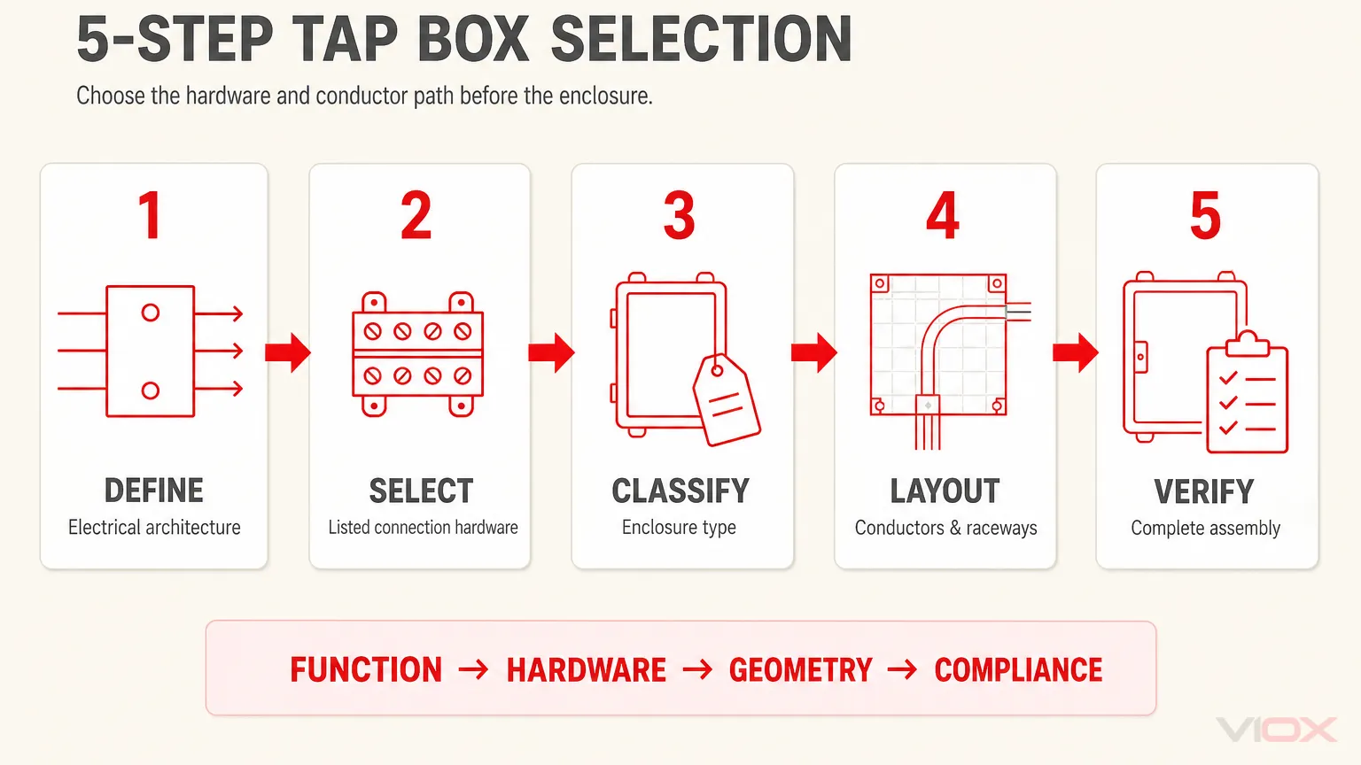
ٹیپ باکس کے انتخاب کا پانچ مرحلہ وار ورک فلو
مرحلہ 1: برقی آرکیٹیکچر کی وضاحت کریں
سسٹم وولٹیج، دستیاب فالٹ کرنٹ، اپ اسٹریم اوور کرنٹ پروٹیکشن، آنے والے کنڈکٹرز، جانے والے کنڈکٹرز، ٹیپس کی تعداد، گراؤنڈنگ اور بانڈنگ کا طریقہ، اور یہ کہ آیا تنصیب سروس کا سامان ہے یا کسی اور لسٹڈ اسمبلی کا حصہ ہے، ان سب کو دستاویزی شکل دیں۔.
مرحلہ 2: لسٹڈ کنکشن ہارڈویئر کا انتخاب کریں
کنیکٹر، ٹرمینل اسمبلی، یا پی ڈی بی (PDB) کا انتخاب اس کے اصل ڈیٹا شیٹ اور تنصیبی ہدایات کے مطابق کریں۔ کنڈکٹر کا مواد، سائز کی حد، فی پورٹ کنڈکٹرز کی تعداد، درجہ حرارت کی ریٹنگ، ٹارک کی ہدایات، اور قابل اطلاق شارٹ سرکٹ کی شرائط کی تصدیق کریں۔.
ایک ٹرمینل میں دو کنڈکٹرز نہ لگائیں جب تک کہ وہ ٹرمینل اس کنڈکٹر کے امتزاج کے لیے مخصوص نہ ہو۔.
مرحلہ 3: انکلوژر (Enclosure) کی درجہ بندی کریں
تعین کریں کہ آیا تنصیب پل/جنکشن باکس، کیبنٹ یا کٹ آؤٹ باکس، وائر وے، یا کسی لسٹڈ آلات کا حصہ ہے۔ یہ درجہ بندی طے کرتی ہے کہ NEC کی کن دفعات کا جائزہ لینا ضروری ہے۔.
مرحلہ 4: طول و عرض کا انتخاب کرنے سے پہلے کنڈکٹرز کی ترتیب طے کریں
ہر ریس وے انٹری، کنڈکٹر کا راستہ، کنیکٹر، اور ٹرمینیشن کو ڈرا کریں۔ مطلوبہ سٹریٹ پل، اینگل پل، سپلائس، اور ٹرمینل بینڈنگ اسپیس چیکس کا اطلاق کریں۔ تصدیق کریں کہ کور کو کنڈکٹرز کو لائیو پارٹس یا تیز کناروں کے خلاف دبائے بغیر انسٹال کیا جا سکتا ہے۔.
مرحلہ 5: مکمل اسمبلی کی تصدیق کریں
رسائی، سپورٹ، بانڈنگ، ماحولیاتی مناسبیت، غیر استعمال شدہ سوراخوں، کور کی مناسبیت، لیبلنگ، کام کرنے کی جگہ، اور مینوفیکچرر کی ہدایات کو چیک کریں۔ AHJ تنصیب کا جائزہ لیتا ہے، نہ کہ صرف خالی باکس کے کیٹلاگ صفحے کا۔.
وائر بینڈنگ اسپیس: وہ موقع جو GSC دکھا رہا ہے
وائر بینڈنگ اسپیس کوئی آرائشی کلیئرنس نہیں ہے۔ یہ کنڈکٹرز کو اس قابل بناتی ہے کہ وہ قابل قبول موڑ سے تجاوز کیے بغیر، ٹرمینل پر بوجھ ڈالے بغیر، یا انکلوژر کے خلاف انسولیشن کو دبائے بغیر ٹرمینلز میں داخل ہو سکیں۔.
کنٹرولنگ کی ضرورت اس بات پر منحصر ہے کہ کنڈکٹرز کہاں ختم ہوتے ہیں اور انکلوژر کی درجہ بندی کیا ہے۔ NEC 312.6 کیبنٹ اور کٹ آؤٹ بکس میں ٹرمینلز پر وائر بینڈنگ کی جگہ سے متعلق ہے، جبکہ NEC 314.28 بڑے کنڈکٹرز پر مشتمل پل اور جنکشن بکس میں طول و عرض اور کنڈکٹر کے راستوں سے متعلق ہے۔ لسٹڈ آلات اور ٹرمینل کی ہدایات کے لیے اضافی جگہ درکار ہو سکتی ہے۔.
اسی وجہ سے، “وائر بینڈنگ اسپیس NEC” کا جواب ایک آفاقی پیمائش کے بجائے ایک فیصلہ سازی کے عمل کے ذریعے دیا جانا چاہیے:
- انکلوژر اور آلات کی قسم کی شناخت کریں؛;
- کنڈکٹر اور ٹرمینل کی شناخت کریں؛;
- اپنائے گئے ایڈیشن میں قابل اطلاق NEC ٹیبل یا جیومیٹری کے اصول کو چیک کریں؛;
- آلات کی ہدایات کو چیک کریں؛;
- صرف خالی بکس کے طول و عرض ہی نہیں، بلکہ کنڈکٹر کے حقیقی راستے کی تصدیق کریں۔.
ڈیزائن کی عام غلطیاں
| غلطی | یہ ناکام کیوں ہوتا ہے | بہتر طریقہ |
|---|---|---|
| PB، JB یا TB لیبل سے سائزنگ | لیبل ہر کنڈکٹر کے راستے یا قابل اطلاق اصول کی وضاحت نہیں کرتا | اندرونی کنڈکٹر کی ترتیب بنائیں اور انکلوژر کی درجہ بندی کریں |
| یہ فرض کرتے ہوئے کہ ہر جنکشن باکس صرف NEC 314.16 کا استعمال کرتا ہے | بڑے کنڈکٹرز 314.28 کے طول و عرض کو بھی متحرک کر سکتے ہیں | حساب کا طریقہ منتخب کرنے سے پہلے کنڈکٹر کے سائز کی جانچ کریں |
| 8× اصول سے بچنے کے لیے اسپلائس کا اضافہ | اسپلائسز کو اینگل/یو-پل جیومیٹری کے ساتھ حل کیا جاتا ہے؛ وہ خود بخود 314.28 کو ختم نہیں کرتے | اصل اسپلائسڈ ترتیب کے لیے انکلوژر کا دوبارہ حساب لگائیں |
| صرف ایمپیئرز کی بنیاد پر ٹیپ باکس کا انتخاب کرنا | ہارڈویئر اور کنڈکٹر کی روٹنگ سائز کو کنٹرول کر سکتی ہے | پہلے کنیکٹر کا انتخاب کریں اور کنڈکٹرز کی میپنگ کریں |
| ریس وے میں داخلے کے فاصلے کو نظر انداز کرنا | مجموعی طول و عرض درست ہو سکتے ہیں جبکہ ہب کے مقامات ناکام ہو سکتے ہیں | ہر دیوار، قطار، اور ایک جیسے کنڈکٹر والے ریس وے کے جوڑے کی پیمائش کریں |
| کسی عام پی ڈی بی (PDB) کو اس کی لسٹنگ چیک کیے بغیر استعمال کرنا | کنڈکٹر کے امتزاج اور شارٹ سرکٹ کی شرائط ماڈل کے لحاظ سے مخصوص ہوتی ہیں۔ | درست پروڈکٹ دستاویزات اور مکمل اسمبلی کے تقاضوں کا استعمال کریں۔ |
| کوڈ کی کم از کم جہتوں کو مکمل ڈیزائن سمجھنا۔ | کم از کم جیومیٹری اب بھی وائرنگ کھینچنے یا ٹرمینیشن کے لیے غیر عملی ہو سکتی ہے۔ | تمام کم از کم جانچ پڑتال کے بعد تنصیب اور دیکھ بھال کے لیے قابل استعمال جگہ چھوڑیں۔ |
انجینئرز اور پینل بنانے والوں کے لیے تصریحی چیک لسٹ۔
ٹیپ، پل، یا جنکشن انکلوژر جاری کرنے سے پہلے، درج ذیل کو ریکارڈ کریں:
- انکلوژر کی درجہ بندی اور مطلوبہ فنکشن؛;
- اپنایا گیا NEC ایڈیشن اور مقامی ترامیم؛;
- کنڈکٹر کے سائز، مقدار، مواد، اور انسولیشن کی اقسام؛;
- ریس وے کے تجارتی سائز اور داخلے کے مقامات؛;
- سیدھے، زاویہ دار، یو-پل، سپلائس، ٹیپ، اور ٹرمینیشن کے راستے؛;
- ہر سمت کے لیے شمار کردہ کم از کم طول و عرض؛;
- ایک ہی کنڈکٹر کے ریس وے میں داخلے کا درمیانی فاصلہ؛;
- کنیکٹر یا پی ڈی بی (PDB) بنانے والی کمپنی اور پارٹ نمبر؛;
- کنڈکٹر کے مجاز امتزاج اور ٹائٹ کرنے کی ہدایات؛;
- آلات اور اسمبلی کی شارٹ سرکٹ ضروریات؛;
- مقام کے لحاظ سے درکار انکلوژر کا مواد اور ماحولیاتی درجہ بندی؛;
- گراؤنڈنگ اور بانڈنگ کا طریقہ کار؛;
- کور، سپورٹ، رسائی، لیبلنگ، اور کام کرنے کی جگہ کے تقاضے؛;
- حساب کردہ کم از کم جگہ سے ہٹ کر اضافی تنصیبی کلیئرنس۔.
اگر پروجیکٹ کو معیاری کنسٹرکشن باکس کے بجائے کنفیگر ایبل انڈسٹریل انکلوژر کی ضرورت ہو، تو VIOX کا جائزہ لیں۔ واٹر پروف جنکشن باکس اور انکلوژر کے اختیارات صرف برقی، ماحولیاتی، اور جہتی تقاضوں کے تعین کے بعد۔.
اکثر پوچھے گئے سوالات
کیا ٹیپ باکس اور جنکشن باکس ایک ہی چیز ہیں؟
ٹیپ باکس ایک قسم کے جنکشن یا ڈسٹری بیوشن انکلوژر کے طور پر کام کر سکتا ہے، لیکن ہر ڈیزائن میں ان اصطلاحات کو ایک دوسرے کی جگہ استعمال نہیں کیا جا سکتا۔ “ٹیپ باکس” سے مراد وہ فیڈر یا سرکٹ ہے جہاں سے ٹیپنگ کی جا رہی ہو؛ جبکہ “جنکشن باکس” وسیع تر معنوں میں ایک ایسے انکلوژر کو بیان کرتا ہے جس میں کنڈکٹر کے کنکشن موجود ہوں۔ لاگو ہونے والے اصول انکلوژر کی درجہ بندی، کنڈکٹر کے سائز، ہارڈویئر اور وائرنگ کے انتظام پر منحصر ہوتے ہیں۔.
کیا ٹیپ باکس میں ہمیشہ پاور ڈسٹری بیوشن بلاک (PDB) موجود ہوتا ہے؟
نہیں۔ ٹیپس میں لسٹڈ سپلائسنگ کنیکٹرز، ٹرمینل اسمبلیاں، بس سٹرکچرز، یا PDBs استعمال ہو سکتے ہیں۔ منتخب کردہ کنکشن کا طریقہ کار کنڈکٹرز اور ایپلی کیشن کے مطابق ہونا چاہیے۔.
کیا NEC 314.28 صرف پل باکسز (pull boxes) پر لاگو ہوتا ہے؟
نہیں۔ NEC 314.28 اپنے دائرہ کار میں پل باکسز، جنکشن باکسز اور کونڈیوٹ باڈیز کا احاطہ کرتا ہے۔ بڑے کنڈکٹرز والے جنکشن باکسز کے لیے بھی 314.28 کے تحت جہتی (dimensional) جانچ کی ضرورت پڑ سکتی ہے۔.
کیا میں کنڈکٹرز کو کاٹ کر اور جوڑ کر (splice) پل باکس کا سائز کم کر سکتا ہوں؟
ایسا فرض نہ کریں۔ سپلائسز NEC 314.28 کی اینگل/یو-پل/سپلائس کی دفعات میں شامل ہیں۔ کنڈکٹر کی ترتیب کو تبدیل کرنے کے لیے نئے حساب کتاب کی ضرورت ہوتی ہے اور اس سے کنیکٹر، موڑنے کی جگہ (bending-space)، رسائی، اور دیکھ بھال کی ضروریات میں اضافہ ہو سکتا ہے۔.
پل باکس کے لیے 8× کا اصول کیا ہے؟
NEC 314.28 کے تحت سیدھے کھنچاؤ (straight pull) کے لیے، کھنچاؤ کی سمت میں باکس کی لمبائی سب سے بڑے ریس وے (raceway) کے ٹریڈ سائز سے کم از کم آٹھ گنا ہونی چاہیے۔ دیگر جہتوں اور تقاضوں کو بھی چیک کرنا ضروری ہے۔.
اینگل پل (angle pull) کے لیے 6 گنا کا اصول کیا ہے؟
اینگل پل، یو-پل (U-pull)، یا سپلائس (splice) کے لیے، ریس وے کے داخلے سے مخالف دیوار تک درکار فاصلہ اس قطار میں موجود سب سے بڑے ریس وے کے چھ گنا اور اسی قطار میں موجود دیگر ریس ویز کے ٹریڈ سائز کے مجموعے پر مبنی ہوتا ہے۔ ایک ہی کنڈکٹر رن کے لیے ریس وے کے درمیانی فاصلے کی تصدیق کرنا بھی ضروری ہے۔.
مجھے NEC کا کون سا ایڈیشن استعمال کرنا چاہیے؟
پروجیکٹ کے دائرہ اختیار میں اپنایا گیا ایڈیشن استعمال کریں، ساتھ ہی مقامی ترامیم اور AHJ کی تشریحات کو بھی مدنظر رکھیں۔ یہ فرض نہ کریں کہ تازہ ترین شائع شدہ ایڈیشن پروجیکٹ کے مقام پر پہلے سے نافذ العمل ہے۔.
نتیجہ
پل باکس، جنکشن باکس، اور ٹیپ باکس کے درمیان فرق کا آغاز ان کے کام سے ہوتا ہے، لیکن محفوظ سائزنگ کا انحصار اصل تنصیب پر ہوتا ہے۔ ڈرائنگ کا لیبل کنڈکٹر کے سائز، ریس وے کی جیومیٹری، سپلائس یا ٹیپ کی ترتیب، ٹرمینل موڑنے کی جگہ، آلات کی لسٹنگ، یا مینوفیکچرر کی ہدایات پر فوقیت نہیں رکھتا۔.
ٹیپ باکس کے لیے، سب سے قابل اعتماد ترتیب یہ ہے: برقی آرکیٹیکچر کی وضاحت کریں، لسٹڈ کنکشن ہارڈویئر کا انتخاب کریں، انکلوژر کی درجہ بندی کریں، کنڈکٹرز کو ترتیب دیں، ہر درکار جہت کا حساب لگائیں، اور مکمل اسمبلی کی تصدیق کریں۔ یہ عمل ایک قابل دفاع تفصیلات تیار کرتا ہے اور بہت جلد منتخب کردہ باکس میں تنصیب کو فٹ کرنے کی غیر محفوظ شارٹ کٹ سے بچاتا ہے۔.
تکنیکی حوالہ جات
- آرٹیکل 314.28 کے لیے NFPA NEC کی ترقیاتی دستاویزات
- آئی سی سی (ICC) کے زیر اہتمام این ای سی (NEC) آرٹیکل 314 کی دفعات
- شنائیڈر الیکٹرک (Schneider Electric) کے انکلوزڈ پاور ڈسٹری بیوشن بلاک سے متعلق معلومات
حفاظتی اور ضابطہ اخلاق کا نوٹ: یہ مضمون ایک انجینئرنگ کا جائزہ ہے، نہ کہ منظور شدہ این ای سی (NEC)، مقامی ترامیم، پروجیکٹ کی تفصیلات، پروڈکٹ کی ہدایات، یا اے ایچ جے (AHJ) کی منظوری کا متبادل۔ الیکٹریکل انکلوژر اور کنڈکٹر کا کام اہل افراد کے ذریعے ڈیزائن اور انجام دیا جانا چاہیے۔.