
It starts with a common scenario in industrial automation: a packaging line stops mid-shift. The maintenance technician traces the fault to a 24VDC solenoid valve that failed to close. Upon inspecting the control panel, they find the time delay relay driving that solenoid has stuck contacts. The relay is rated for 10 Amps, and the solenoid only draws 0.5 Amps. Why did a 10A relay fail on a 0.5A load?
This situation is a classic example of inductive load failure, a pervasive issue that costs manufacturing facilities thousands of dollars in downtime and replacement parts annually. While resistive loads like heaters and incandescent lamps are straightforward to switch, inductive loads—such as solenoid valves, motor brakes, contactor coils, and electromagnetic clutches—behave like compressed springs. When you release them (open the circuit), they release stored energy violently.
For senior electrical engineers and panel builders, understanding the physics behind this failure is critical. It is not a matter of quality control; it is a matter of physics and specification. The difference lies in understanding IEC 60947 utilization categories, specifically the critical distinction between AC-1 and AC-15 ratings. This article dissects why time relay contacts fail on inductive loads and provides the engineering frameworks to prevent it.
The Hidden Enemy: What Makes Inductive Loads So Destructive
To understand why contacts weld or erode, we must look at the nature of the load itself. Unlike resistive loads, where current and voltage are in phase and energy is dissipated as heat, inductive loads store energy in a magnetic field.
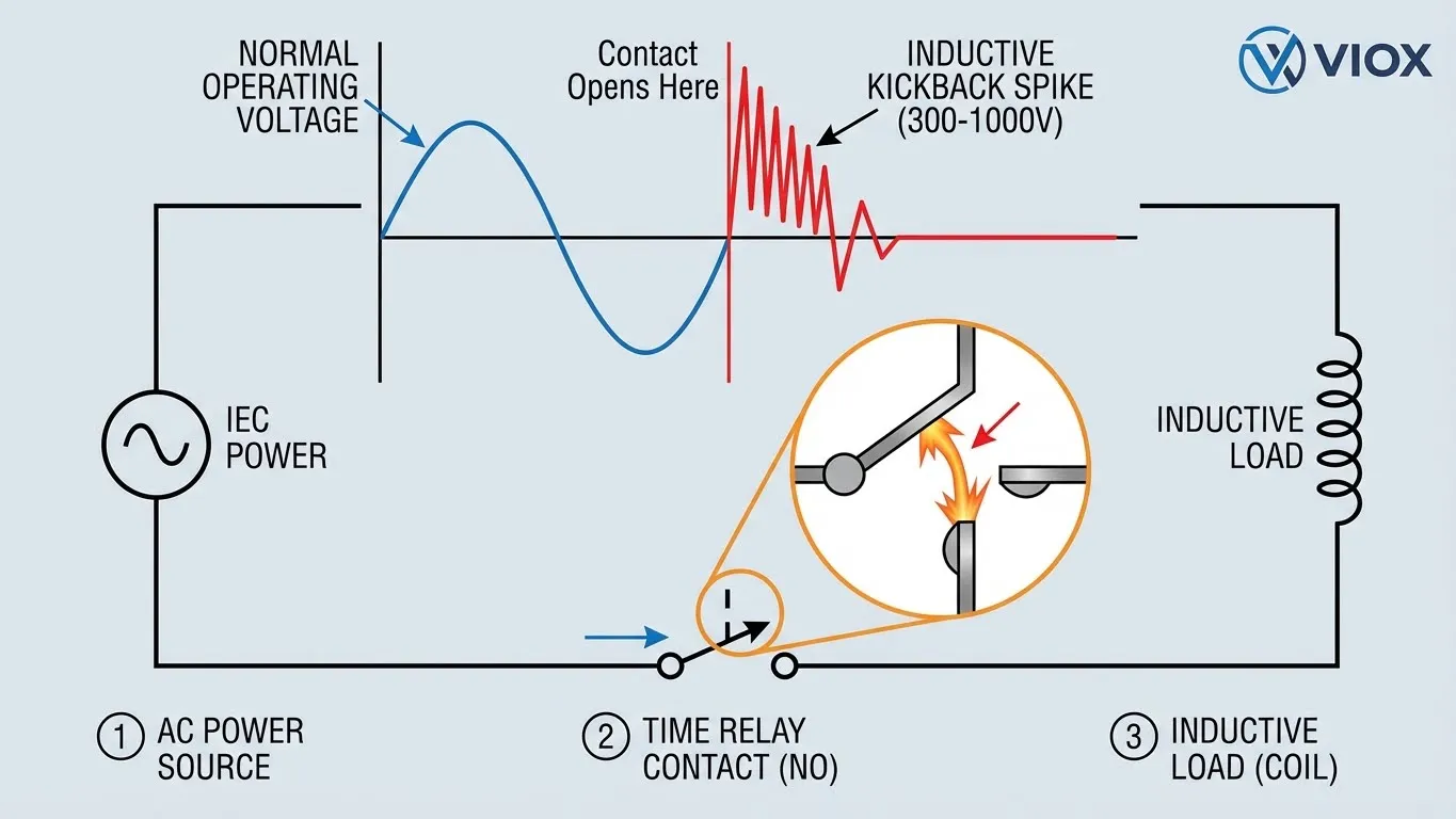
When a time relay energizes an inductive load (like a solenoid coil), current builds up to create a magnetic field. The real danger occurs when the relay contacts open to de-energize the load. According to Lenz’s Law, the collapsing magnetic field induces a voltage that opposes the change in current (V = -L · di/dt). Because the contact gap is opening rapidly (di/dt is very high), the inductor fights to keep the current flowing, generating a massive voltage spike known as inductive kickback သို့မဟုတ် back EMF.
The Physics of Failure
- Voltage Spikes: Without suppression, a 24V coil can generate a spike of 300V to 1,000V. A 230V AC motor brake can generate spikes exceeding 3,000V.
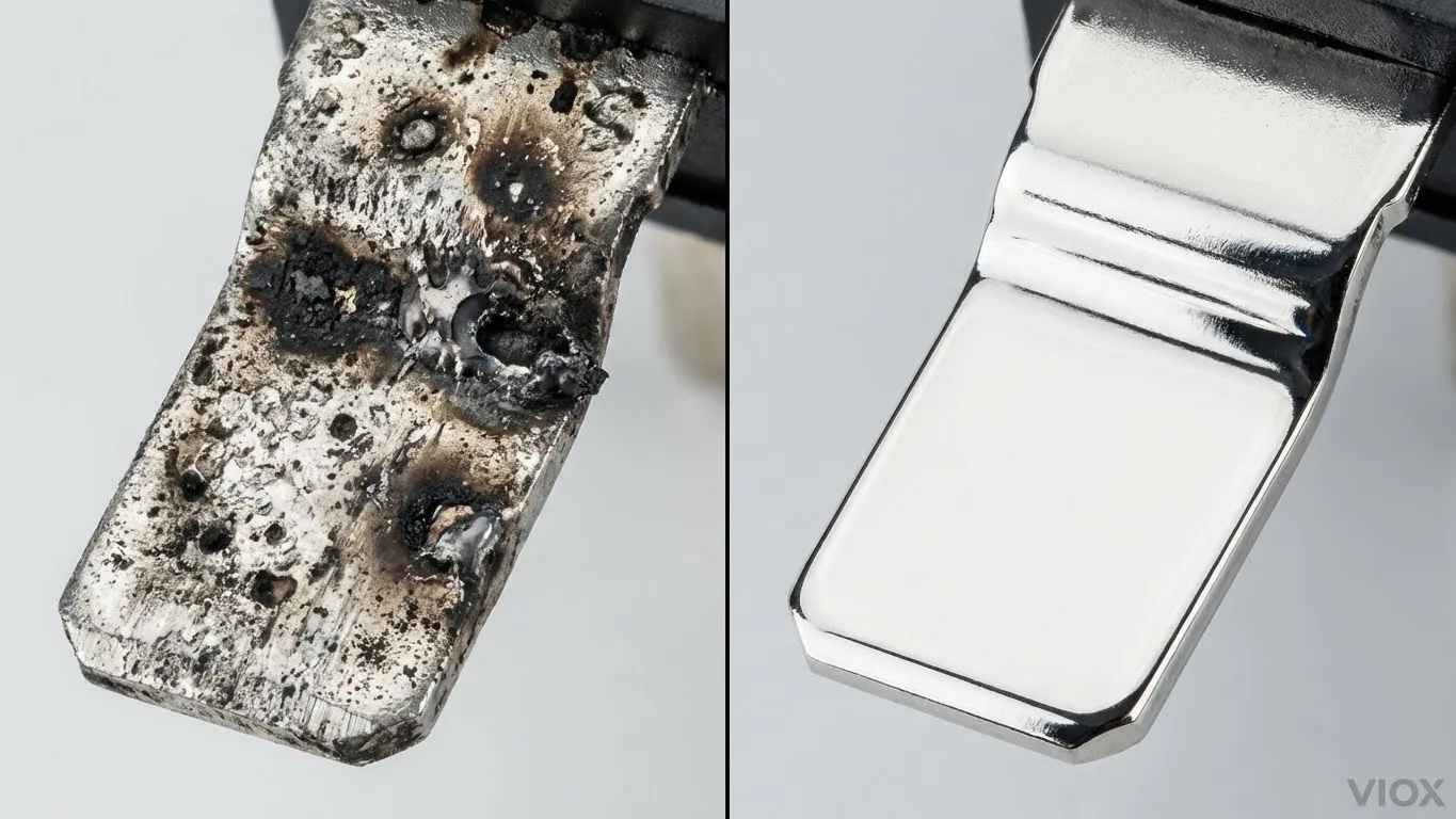
- Arcing: This high voltage ionizes the air between the opening contacts, creating a plasma arc. This arc can reach temperatures of 5,000°C to 10,000°C—hotter than the surface of the sun.
- Material Transfer: The intense heat melts microscopic portions of the silver alloy contact material. As the arc extinguishes and re-strikes (especially in AC circuits), molten metal is transferred between contacts, leaving pits and craters.
- Welding: If the relay is re-closed while the contacts are still molten or if the inrush current is too high during the “make” operation, the contacts fuse together. The next time the automation logic signals the relay to open, it physically cannot.
For a deeper dive into the differences between component ratings, see our guide on Circuit Protection Selection Frameworks.
Decoding IEC 60947-5-1: AC-1 vs. AC-15 Utilization Categories
The most common mistake in specifying time delay relays is looking only at the “Resistive Load” rating (often printed largest on the housing) and assuming it applies to all applications. The International Electrotechnical Commission (IEC) standard 60947-5-1 defines specific သုံးချမျိုးအစားများ that predict how a relay will perform under different electrical stresses.
The two most relevant categories for time relays are သတ္မွတ္အ-၁ နှင့် သတ္မွတ္အ-၁၅.
| အင်္ဂါ | AC-1 (Resistive / Low Inductive) | AC-15 (Electromagnetic Loads) |
|---|---|---|
| Primary Definition | Non-inductive or slightly inductive loads. | Control of AC electromagnetic loads greater than 72VA. |
| Power Factor (cos φ) | ≥ 0.95 | ≤ 0.3 (Testing condition) |
| ပံုမွန္အသံုးခ်ျခင္း | Resistive heaters, incandescent lighting, signaling lamps, pure resistance inputs. | Solenoid valves, contactor coils, magnetic brakes, electromagnetic clutches. |
| Make Current | 1x Rated Current (ငါင) | 10x Rated Current (ငါင) |
| Break Current | 1x Rated Current (ငါင) | 1x Rated Current (ငါင) |
| Break Voltage Stress | 1x Rated Voltage (Uင) | 1x Rated Voltage (Uင) + High Inductive Kickback |
| Contact Stress Level | Low. Arcing is minimal and easily extinguished. | Severe. Heavy inrush creates weld risks; inductive break creates heavy arcing. |
| Typical Electrical Life | 100,000+ operations at full load. | မကြာခဏ < 25,000 operations if wrongly specified; significantly reduced without suppression. |
Why the Difference Matters
A relay contact rated for 10A AC-1 might only be rated for 1.5A or 3A AC-15.
AC-15 အတွက်တည်ဆောက်ထားသော Relay များတွင် အောက်ပါအချက်များ ပါဝင်လေ့ရှိသည်။
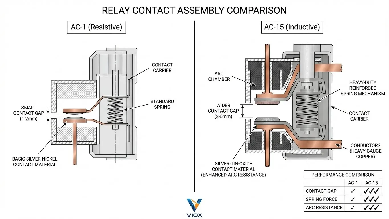
- မတူညီသော Contact ပစ္စည်းများ Silver-Tin-Oxide ကိုအသုံးပြုခြင်း (AgSnO2) Silver-Nickel အစား (AgNi) ဂဟေဆက်ခြင်းကိုခံနိုင်ရည်ရှိသည်။.
- ပိုမိုအားကောင်းသော Spring ယန္တရားများ contacts များကိုပိုမိုမြန်ဆန်စွာဖွင့်ရန်နှင့် arcs များကိုပိုမိုမြန်ဆန်စွာငြိမ်းသတ်ရန်။.
- ပိုမိုကျယ်ပြန့်သော Contact ကွာဟချက်များ ပွင့်နေသော contacts များအကြား dielectric ခွန်အားကိုတိုးမြှင့်ရန်။.
AC-15 load ကိုပြောင်းရန် AC-1 rated relay ကိုအသုံးပြုပါက၊ သင်သည် race car ကို off-road သို့မောင်းနှင်နေခြင်းနှင့်တူပါသည်။ မိုင်အနည်းငယ်ကြာအောင်အလုပ်လုပ်နိုင်သော်လည်း suspension (သို့မဟုတ်ဤကိစ္စတွင် contact မျက်နှာပြင်) သည်နောက်ဆုံးတွင်ကွဲအက်သွားလိမ့်မည်။.
သင်၏ Relay Contacts များပျက်ကွက်ရသည့်အကြောင်းရင်း- အဓိကအကြောင်းရင်း ၅ ချက်
VIOX တွင်ပြန်လည်ရောက်ရှိလာသောကုန်ပစ္စည်းများသို့မဟုတ် field failures များကိုခွဲခြမ်းစိတ်ဖြာသောအခါ၊ ကျွန်ုပ်တို့သည်အဓိကအကြောင်းရင်းကိုအချက် ၅ ချက်အနက်မှတစ်ခုသို့အမြဲခြေရာခံသည်။.
အကြောင်းရင်း ၁- မှားယွင်းသော Utilization အမျိုးအစားရွေးချယ်မှု
ဤသည်မှာအဖြစ်အများဆုံးအမှားဖြစ်သည်။ အင်ဂျင်နီယာတစ်ဦးသည် datasheet တွင် “10A 250VAC” ကိုမြင်ပြီး 5A solenoid valve ကိုချိတ်ဆက်သည်။ သို့သော် 10A rating သည် resistive load များအတွက်သာဖြစ်သည်။ (AC-1) ထို relay အတွက် inductive rating သည် 2A သာဖြစ်နိုင်သည်။ 5A solenoid သည်၎င်း၏ inductive စွမ်းရည်နှင့်နှိုင်းယှဉ်ပါက contact ကို 250% ဖြင့် overload လုပ်သည်။.
အကြောင်းရင်း ၂- Inrush Current Surge
Inductive load များ၊ အထူးသဖြင့် AC solenoids နှင့် contactors များသည် magnet ပွင့်နေချိန်တွင် impedance နည်းပါးသည်။ (လေကွာဟချက်) ၎င်းတို့သည် ကြီးမားသော inrush current—ပုံမှန်အားဖြင့် steady-state “holding” current ထက် ၅ ဆမှ ၁၀ ဆ— magnet ကိုအားသွင်းရန်ဆွဲယူသည်။.
- ပျက်ကွက်ခြင်း- relay contacts များပိတ်သွားသည်နှင့်အမျှ ၎င်းတို့သည် အဏုကြည့်မှန်ပြောင်းဖြင့် ပြန်ခုန်သည်။ ဤခုန်ခြင်းသည် 10x inrush peak အတွင်းဖြစ်ပေါ်ပါက ပြင်းထန်သောအပူသည် spot weld ကိုဖန်တီးပေးသည်။.
အကြောင်းရင်း ၃- Inductive Kickback Voltage Spikes
“Hidden Enemy” အပိုင်းတွင်ဖော်ပြထားသည့်အတိုင်း break operation သည် arc ပျက်စီးမှုဖြစ်ပွားသည့်နေရာဖြစ်သည်။.
- ပျက်ကွက်ခြင်း- ထပ်ခါထပ်ခါ arcing သည် contact တစ်ခုမှတစ်ခုသို့သတ္တုကိုလွှဲပြောင်းပေးသည် (material migration)။ နောက်ဆုံးတွင် contacts များသည် မျက်နှာပြင်ကြမ်းတမ်းမှုကြောင့် စက်ပိုင်းဆိုင်ရာအရ အတူတကွသော့ခတ်သွားကြသည် သို့မဟုတ် လျှပ်စစ်ချိတ်ဆက်မှုကို မပြုလုပ်နိုင်တော့သည်အထိ လုံးဝတိုက်စားခံရသည်။.
အကြောင်းရင်း ၄- မလုံလောက်သော Arc Suppression
panel တည်ဆောက်သူအများအပြားသည် relay ၏အတွင်းပိုင်းလေကွာဟချက်သည် arc ကိုကိုင်တွယ်ရန်လုံလောက်သည်ဟုယူဆကြသည်။ AC-15 load များအတွက် ၎င်းသည်ရှားပါးသည်။ ပြင်ပ snubbers သို့မဟုတ် varistors (MOVs) မပါဘဲ arc သည်လိုအပ်သည်ထက် milliseconds အနည်းငယ်ကြာရှည်ခံပြီး wear ကိုအရှိန်မြှင့်ပေးသည်။.
အကြောင်းရင်း ၅- ပတ်ဝန်းကျင်နှင့် စက်ပိုင်းဆိုင်ရာအချက်များ
- High Duty Cycle- လျင်မြန်စွာ cycling (ဥပမာ၊, < 1 စက္ကန့်ကြားကာလ) သည် contacts များအား လည်ပတ်မှုများကြားတွင် အေးသွားခြင်းမှ တားဆီးပေးပြီး thermal runaway သို့ ဦးတည်စေသည်။.
- ညစ်ညမ်းမှု- panel အတွင်းရှိ ဖုန်မှုန့်များ သို့မဟုတ် ဓာတုအငွေ့များသည် contacts များပေါ်တွင် အခြေချနိုင်ပြီး ခုခံမှုကို တိုးမြင့်စေပြီး အပူကိုဖြစ်စေသည်။.
- အပူချိန် relays များကို ၎င်းတို့၏ rated ambient temperature အထက်တွင် လည်ပတ်ခြင်းသည် ၎င်းတို့၏ current သယ်ဆောင်နိုင်စွမ်းကို လျော့နည်းစေသည်။ ကျွန်ုပ်တို့၏ဆောင်းပါးကိုကြည့်ပါ။ Electrical Derating Factors for more details.
မှန်ကန်သော Time Relay Contact Rating ကိုမည်သို့ရွေးချယ်မလဲ
မှန်ကန်သော relay ကိုရွေးချယ်ခြင်းသည် စနစ်တကျချဉ်းကပ်ရန်လိုအပ်သည်။ ခန့်မှန်းမနေပါနှင့်—တွက်ချက်ပါ။.
Contact ရွေးချယ်မှုအတွက် ဆုံးဖြတ်ချက် Matrix
| ဝန်အမျိုးအစား | သွင်ပြင်လက္ခဏာများ | အကြံပြုထားသော Contact ပစ္စည်း | Derating Factor (vs AC-1) |
|---|---|---|---|
| Resistive Heater | Pure resistance, PF=1.0 | AgNi (Silver Nickel) | 1.0 (Derating မရှိပါ) |
| Contactor Coil | High inrush, moderate inductance | AgSnO2 (Silver Tin Oxide) | 0.3 – 0.4 |
| Solenoid Valve | High inrush, high inductance | AgSnO2 | 0.2 – 0.3 |
| Motor Brake | Extreme inductance, severe kickback | AgSnO2 + ပြင်ပ Contactor | 0.15 – 0.2 |
| မီးခွက် | High inrush (cold filament) | AgSnO2 (Silver Tin Oxide) | 0.1 (10x inrush ကြောင့်) |
ခြေလှမ်းအားဖြင့်အဆင့်ရွေးချယ်ခြင်းလုပ်ငန်းစဉ်
- Load ကိုခွဲခြားသတ်မှတ်ပါ- ၎င်းသည် heater (AC-1) သို့မဟုတ် solenoid/motor (AC-15) လား။
- Steady-State Current ကိုဆုံးဖြတ်ပါ (ငါhold): load ၏ datasheet ကိုစစ်ဆေးပါ။.
- Inrush Current ကိုတွက်ချက်ပါ (ငါinrush): inductive AC load များအတွက် 10 × ကိုယူဆပါ။ ငါhold.
- Relay Datasheet ကိုစစ်ဆေးပါ- အထူးသဖြင့် သတ္မွတ္အ-၁၅ rating ကိုရှာပါ။ AC-1 သာစာရင်းသွင်းထားပါက AC-15 rating သည် 15-20% AC-1 rating ၏ဖြစ်သည်။.
- ဗို့အားကိုစစ်ဆေးပါ: ရီလေးဗို့အားအဆင့်သတ်မှတ်ချက်သည် စနစ်ဗို့အားထက် ကျော်လွန်ကြောင်းသေချာပါစေ။.
- ထုတ်ကုန်ကိုရွေးချယ်ပါ: AC-15 အဆင့်သတ်မှတ်ချက် > Load ဖြစ်သော ရီလေးကိုရွေးချယ်ပါ။ ငါhold.
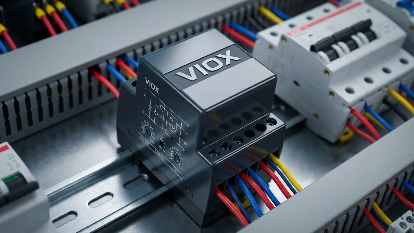
ခိုင်မာသောစက်မှုလုပ်ငန်းသုံးများအတွက်၊ VIOX စက်မှုအချိန်ရီလေးများကို အကြံပြုပါသည်။ ၎င်းတို့ကို AC-15 duty cycles များအတွက် အထူးစမ်းသပ်ပြီး အဆင့်သတ်မှတ်ထားပါသည်။.
VIOX Time Delay Relays များကိုလေ့လာပါ
ကာကွယ်ရေးနည်းဗျူဟာများ- အဆက်အသွယ်ပျက်စီးခြင်းကို ကာကွယ်ခြင်း
မှန်ကန်သောရီလေးဖြင့်ပင်၊ inductive load များသည် ပြင်းထန်သည်။ ကာကွယ်ရေးနည်းဗျူဟာများကို အကောင်အထည်ဖော်ခြင်းသည် အဆက်အသွယ်သက်တမ်းကို စက်ဝန်း ၂၀,၀၀၀ မှ ၁,၀၀၀,၀၀၀ ကျော်အထိ တိုးမြှင့်နိုင်သည်။.
နည်းဗျူဟာ ၁- မှန်ကန်စွာ အဆင့်သတ်မှတ်ထားသော အဆက်အသွယ်များကို အသုံးပြုပါ
သင်၏ load သည် inductive ဖြစ်ပါက AC-15 အတွက် အတိအကျအဆင့်သတ်မှတ်ထားသော အဆက်အသွယ်များကို အမြဲသတ်မှတ်ပါ။ ဒေတာစာရွက်တွင် AC-15 ကို မသတ်မှတ်ထားပါက၊ solenoids သို့မဟုတ် motors များအတွက် ပြင်းထန်စွာ derating မပါဘဲ မသုံးပါနှင့်။.
နည်းဗျူဟာ ၂- Arc Suppression ကို အကောင်အထည်ဖော်ပါ
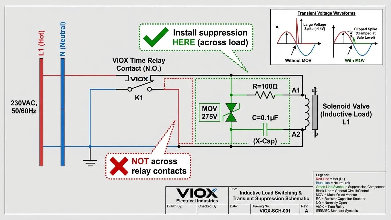
Suppression devices များသည် သံလိုက်စက်ကွင်းမှ ထုတ်လွှတ်သော စွမ်းအင်ကို စုပ်ယူပြီး ရီလေးအဆက်အသွယ်များတစ်လျှောက် arcing ဖြစ်ခြင်းမှ ကာကွယ်ပေးသည်။ ၎င်းတို့ကို အမြဲတပ်ဆင်သင့်သည်။ load နှင့်အပြိုင်, ရီလေးအဆက်အသွယ်များတစ်လျှောက်မဟုတ်ပါ (ယိုစိမ့်မှုပြဿနာများဖြစ်စေနိုင်သည်)။.
Arc Suppression အတွက် နည်းပညာဆိုင်ရာ သတ်မှတ်ချက်များ
| စနစ်ဗို့ | Suppression Device | အကြံပြုထားသော Specs | ၂၁၁။ တပ်ဆင်ခြင်းမှတ်စုများ |
|---|---|---|---|
| 24 VDC | Freewheeling Diode | 1N4007 သို့မဟုတ် အလားတူ | Cathode သည် positive သို့။ drop-out time ကို အနည်းငယ်နှေးကွေးစေသည်။. |
| 24 VAC | RC Snubber သို့မဟုတ် MOV | MOV: ~30-40V clamping | solenoid terminals တွင် တိုက်ရိုက်တပ်ဆင်ပါ။. |
| 120 VAC | RC Snubber + MOV | MOV: 150-275V clamping | Capacitor: 0.1µF – 0.47µF, Resistor: 47Ω – 100Ω (1/2W) |
| 230 VAC | RC Snubber + MOV | MOV: 275-300V clamping | Capacitor: 0.1µF – 0.47µF (X2 rated), Resistor: 100Ω – 220Ω |
suppression နည်းပညာများ၏ အသေးစိတ်နှိုင်းယှဉ်မှုအတွက်၊ ကျွန်ုပ်တို့၏ Freewheeling Diode vs. Surge Arrester Guide ကိုဖတ်ပါ။.
နည်းဗျူဟာ ၃- Zero-Crossing Switching ကို ထည့်သွင်းစဉ်းစားပါ
Solid-state relays (SSRs) သို့မဟုတ် zero-crossing circuits ပါသော အထူးပြု electromechanical relays များသည် AC sine wave voltage သည် သုညတွင်ရှိသောအခါ load ကိုဖွင့် သို့မဟုတ် ပိတ်သည်။ ၎င်းသည် arc အတွက်ရရှိနိုင်သောစွမ်းအင်ကို အနည်းဆုံးဖြစ်စေသည်။ ပိုမိုစျေးကြီးသော်လည်း၊ ၎င်းသည် မကြာခဏ စက်ဝန်းအသုံးပြုမှုများအတွက် အလွန်ထိရောက်သည်။.
နည်းဗျူဟာ ၄- Upsize and Derate
သင်သည် suppression ကိုထည့်၍မရပါက၊ ရီလေးကို ရိုးရှင်းစွာ oversizing လုပ်ခြင်းသည် မှန်ကန်သောနည်းဗျူဟာဖြစ်သည်။ သင်၏ load သည် 2A ဆွဲပါက၊ 10A AC-15 (သို့မဟုတ် 10A AC-1 relay derated heavily) အတွက် အဆင့်သတ်မှတ်ထားသော ရီလေးကိုသုံးပါ။ ပိုကြီးသောအဆက်အသွယ်မျက်နှာပြင်ဧရိယာသည် အပူကိုပိုမိုကောင်းမွန်စွာ စုပ်ယူနိုင်ပြီး တိုက်စားမှုကို ပိုမိုခံနိုင်ရည်ရှိသည်။.
နည်းဗျူဟာ ၅- ပုံမှန်ပြုပြင်ထိန်းသိမ်းခြင်း
အရေးကြီးသောအသုံးချပရိုဂရမ်များတွင် (လျှပ်စစ်ဓာတ်အားပေးစက်ရုံထိန်းချုပ်မှု သို့မဟုတ် လေးလံသောထုတ်လုပ်မှုကဲ့သို့)၊ သင်၏ပြုပြင်ထိန်းသိမ်းမှုအချိန်ဇယားတွင် အဆက်အသွယ်စစ်ဆေးခြင်းကို ထည့်သွင်းပါ။ ကာဗွန်တည်ဆောက်မှု သို့မဟုတ် ချိုင့်ခွက်များကို ရှာဖွေပါ။ ကျွန်ုပ်တို့၏ Industrial Contactor Maintenance Checklist လေးလံသောရီလေးများနှင့်လည်း သက်ဆိုင်သည့် စစ်ဆေးရေးပရိုတိုကောများအတွက် ကိုးကားပါ။.
လက်တွေ့အသုံးချမှုဥပမာ
ဇာတ်လမ်း- အလိုအလျောက်အင်ဂျင်နီယာတစ်ဦးသည် အချိန်နှောင့်နှေးရီလေးကို အသုံးပြု၍ ဟိုက်ဒရောလစ်ဆိုလီနွိုက်အဆို့ရှင်ကို ထိန်းချုပ်ရန်လိုအပ်သည်။.
- Load: 230VAC Solenoid Valve
- ပါဝါ- 150 VA (Volt-Amperes) holding power
- ထိန်းချုပ်ဗို့အား- 230VAC
တွက်ချက်မှု-
- Steady State Current: I = P / V = 150 / 230 = 0.65 Amps.
- Inrush Current ခန့်မှန်းချက်: 0.65 × 10 = 6.5 Amps.
- Load အမျိုးအစား: အလွန် inductive (AC-15)။.
“Standard” အမှား:
အင်ဂျင်နီယာသည် စျေးပေါသောရီလေးကို ရွေးချယ်သည်။ “5A 250VAC”.
- Hidden spec: ထို 5A သည် AC-1 (resistive) ဖြစ်နိုင်ဖွယ်ရှိသည်။.
- Real capability: AC-15 အဆင့်သတ်မှတ်ချက်သည် ~0.5A မှ 1A သာဖြစ်နိုင်သည်။.
- Result: 6.5A inrush current သည် welding limit အနီးတွင်ရှိသည်။ break arc သည် အဆက်အသွယ်များကို လျင်မြန်စွာ တိုက်စားစေမည်ဖြစ်သည်။ ရက်သတ္တပတ်အတွင်း ပျက်ကွက်ရန် မျှော်လင့်ထားသည်။.
VIOX အင်ဂျင်နီယာဖြေရှင်းချက်:
အင်ဂျင်နီယာသည် VIOX စက်မှု Timer Relay ကို ရွေးချယ်သည်။.
- Spec Check: ဒေတာစာရွက်တွင် “AC-15 အဆင့်သတ်မှတ်ချက်- 3A @ 230VAC” ဟုဖော်ပြထားသည်။.
- အပိုပစ္စည်း- 3A စွမ်းရည် > 0.65A ဝန်။ (ကိုင်ထားနိုင်သော လျှပ်စီးကြောင်းတွင် 4.6x လုံခြုံရေးအချက်)။.
- ကာကွယ်မှု- အင်ဂျင်နီယာသည် ဆိုလီနွိုက်ကွိုင်အဆက်များတွင် 275V MOV တစ်ခုကို တပ်ဆင်သည်။.
- Result: နှစ်ပေါင်းများစွာ ယုံကြည်စိတ်ချရသော လုပ်ဆောင်ချက်။.
သော့ထုတ်ယူမှုများ
- Inductive ဝန်များက ပြန်ခုခံသည်- ဆိုလီနွိုက်များနှင့် မော်တာများသည် ဗို့အားမြင့်တက်မှုများနှင့် လျှပ်စစ်မီးပွားများ ထုတ်ပေးပြီး စံအဆက်အသွယ်များကို ပျက်စီးစေသည်။.
- သင်၏ အမျိုးအစားများကို သိပါ- သတ္မွတ္အ-၁ သည် ခုခံအားရှိသော ဝန်များအတွက်ဖြစ်သည်။; သတ္မွတ္အ-၁၅ သည် လျှပ်စစ်သံလိုက်ဝန်များအတွက်ဖြစ်သည်။ ၎င်းတို့ကို ဘယ်တော့မှ မရောထွေးပါနှင့်။.
- လျှော့ချခြင်းသည် မဖြစ်မနေလိုအပ်သည်- အကယ်၍ ရီလေးတစ်ခုသည် AC-1 အဆင့်သတ်မှတ်ချက်ကိုသာ ဖော်ပြပါက၊ ၎င်းကို လျှော့ချပါ။ 40-60% inductive အသုံးချမှုများအတွက်။.
- ဖိနှိပ်ခြင်းသည် ရပ်ဆိုင်းချိန်ထက် စျေးသက်သာသည်- $0.50 MOV သို့မဟုတ် RC snubber သည် $50 ရီလေးနှင့် $5,000 ထုတ်လုပ်မှု ရပ်ဆိုင်းချိန်ကို သက်သာစေနိုင်သည်။.
- Inrush ကိုစစ်ဆေးပါ- AC ကွိုင်များအတွက် 10x inrush လျှပ်စီးကြောင်းကို အမြဲတွက်ချက်ပြီး ရီလေး၏ “ပြုလုပ်” စွမ်းရည်သည် ၎င်းကို ကိုင်တွယ်နိုင်ကြောင်း သေချာပါစေ။.
- VIOX ဖြင့် အတည်ပြုပါ- သံသယရှိလျှင် တိုင်ပင်ပါ။ VIOX အချိန် ရီလေးရွေးချယ်မှု လမ်းညွှန်များ သင့်လျှောက်လွှာအတွက် သီးခြားထုတ်ကုန်နှင့် ကိုက်ညီစေရန်။.
အမေးများသောမေးခွန်းများ (FAQ)
မေး- သေးငယ်သော ဆိုလီနွိုက်အဆို့ရှင်အတွက် AC-1 အဆင့်သတ်မှတ်ထားသော ရီလေးကို သုံးနိုင်ပါသလား။
ဖြေ- ရီလေးကို သိသိသာသာ လျှော့ချမှသာ ဖြစ်နိုင်သည်။ ဥပမာအားဖြင့်၊ 10A AC-1 ရီလေးသည် 1A ဆိုလီနွိုက်အဆို့ရှင်ကို ကိုင်တွယ်နိုင်သော်လည်း inductive switching သက်တမ်းမျဉ်းကွေးများအတွက် ထုတ်လုပ်သူ၏ အချက်အလက်များကို သင်အတည်ပြုရပါမည်။ လျှပ်စစ်မီးပွား ဖိနှိပ်ခြင်းကို အထူးအကြံပြုလိုပါသည်။.
မေး- အဆက်အသွယ် ဂဟေဆက်ခြင်းနှင့် အဆက်အသွယ် တိုက်စားခြင်းကြား ကွာခြားချက်ကဘာလဲ။
A- ဂဟေဆက်ခြင်း များသောအားဖြင့် အဆက်အသွယ်များကို အရည်ပျော်စေသော မြင့်မားသော inrush လျှပ်စီးကြောင်းကြောင့် “ပြုလုပ်” (ပိတ်ခြင်း) လုပ်ဆောင်နေစဉ်အတွင်း ဖြစ်ပေါ်ပြီး ၎င်းတို့ကို ပေါင်းစပ်စေသည်။. တိုက်စားခြင်း လျှပ်စစ်မီးပွားကြောင့် “ဖြတ်” (ဖွင့်ခြင်း) လုပ်ဆောင်နေစဉ်အတွင်း ဖြစ်ပေါ်ပြီး ချိတ်ဆက်မှု ပျောက်ဆုံးသည်အထိ အဆက်အသွယ်ပစ္စည်းကို တဖြည်းဖြည်း လောင်ကျွမ်းစေသည်။.
မေး- ကျွန်ုပ်၏ ရီလေးသည် AC-15 အဆင့်သတ်မှတ်ထားပါက snubber လိုအပ်ပါသလား။
ဖြေ- AC-15 ရီလေးများသည် လျှပ်စစ်မီးပွားများကို ပိုမိုခံနိုင်ရည်ရှိအောင် တည်ဆောက်ထားသော်လည်း snubber ထည့်ခြင်းသည် အကောင်းဆုံးအလေ့အကျင့်ဖြစ်သည်။ ၎င်းသည် ခံနိုင်ရည်ရှိရုံသာမက လျှပ်စစ်မီးပွား၏ အရင်းခံအကြောင်းရင်း (ဗို့အားမြင့်တက်မှု) ကို ဖယ်ရှားပေးပြီး ရီလေး၏ လျှပ်စစ်သက်တမ်းကို သိသိသာသာ တိုးစေသည်။.
မေး- မှန်ကန်သော MOV ဗို့အား အဆင့်သတ်မှတ်ချက်ကို မည်သို့တွက်ချက်ရမည်နည်း။
ဖြေ- သင်၏ မျှော်မှန်းထားသော လိုင်းဗို့အားအထက်တွင် Maximum Continuous Operating Voltage (MCOV) ရှိသော MOV ကို ရွေးချယ်ပါ။ 120VAC လိုင်းများအတွက်၊ 150V MCOV သည် အသုံးများသည်။ 230VAC အတွက် 275V သို့မဟုတ် 300V ကိုသုံးပါ။ ပုံမှန်ဗို့အားနှင့် အလွန်နီးကပ်စွာ မထားပါနှင့်၊ သို့မဟုတ် ပုံမှန်လိုင်းအတက်အကျများသည် အပူလွန်ကဲစေနိုင်သည်။.
မေး- လျှပ်စီးကြောင်းသည် အဆင့်သတ်မှတ်ချက်အတွင်းရှိသော်လည်း ကျွန်ုပ်၏ အဆက်အသွယ်များ အဘယ်ကြောင့် ပျက်ကွက်ရသနည်း။
ဖြေ- သင်သည် ခုခံအား (AC-1) အဆင့်သတ်မှတ်ချက်ကို ကြည့်ရှုနိုင်သော်လည်း inductive ဝန်ကို ပြောင်းနေခြင်း ဖြစ်နိုင်သည်။ သို့မဟုတ် ပတ်ဝန်းကျင် အပူချိန်သည် မြင့်မားလွန်းသောကြောင့် အပူလျှော့ချရန် လိုအပ်သည်။ ဒေတာစာရွက်ပေါ်ရှိ အသုံးပြုမှု အမျိုးအစားကို စစ်ဆေးပါ။.
မေး- Solid-state relays (SSRs) များသည် ဤပြဿနာကို ဖြေရှင်းနိုင်ပါသလား။
ဖြေ- ဟုတ်ကဲ့။ SSR များတွင် ရွေ့လျားနေသော အစိတ်အပိုင်းများ မပါရှိသောကြောင့် ၎င်းတို့သည် စက်ပိုင်းဆိုင်ရာအရ ဂဟေဆက်ခြင်း သို့မဟုတ် တိုက်စားခြင်း မပြုလုပ်နိုင်ပါ။ သို့သော် ၎င်းတို့သည် ဗို့အားမြင့်တက်မှုများကြောင့် ပျက်စီးနိုင်ချေရှိသောကြောင့် သင့်လျော်သော varistor ကာကွယ်မှုသည် electromechanical relays များထက် SSR များတွင် ပို၍ပင် အရေးကြီးပါသည်။.
မေး- ဤရီလေးများအတွက် ဝါယာကြိုး တပ်ဆင်ခြင်းဆိုင်ရာ နောက်ထပ်အချက်အလက်များကို ဘယ်မှာရှာနိုင်မလဲ။
ဖြေ- သင့်လျော်သော အဆုံးသတ်ခြင်းသည် ရီလေးရွေးချယ်ခြင်းကဲ့သို့ပင် အရေးကြီးပါသည်။ ကျွန်ုပ်တို့၏ Terminal Block ရွေးချယ်ရေးလမ်းညွှန် panel ဝါယာကြိုးအတွက် အကောင်းဆုံးအလေ့အကျင့်များအတွက်။.
