
ထိန်းချုပ်စနစ်တစ်ခုကို သတ်မှတ်နေပါသလား—မည်သည့် Relay နည်းပညာကို ရွေးချယ်မလဲ။

အပူပေးစက်များ၊ မော်တာများ သို့မဟုတ် ဆိုလီနွိုက်များကို တစ်ရက်လျှင် ရာနှင့်ချီ၍ ပြောင်းရန်လိုအပ်သော ထိန်းချုပ်ဘောင်တစ်ခုကို သင်ဒီဇိုင်းဆွဲနေပါသည်။ သင်၏အကြီးအကဲက ပြုပြင်ထိန်းသိမ်းမှုအနည်းဆုံးဖြစ်စေလိုသည်။ ထုတ်လုပ်မှုမန်နေဂျာက ရပ်နားချိန်မရှိစေလိုသည်။ ဝယ်ယူရေးအဖွဲ့က ကုန်ကျစရိတ်သက်သာသော အစိတ်အပိုင်းများကို လိုချင်သည်။.
သင်သည် ကတ်တလောက်ကိုဖွင့်လိုက်သောအခါ ရွေးချယ်စရာနှစ်ခုကို တွေ့ရသည်- ရိုးရာလျှပ်စစ်သံလိုက် Relay များနှင့် Solid-State Relay (SSR) များဖြစ်သည်။ SSR သည် သုံးဆပိုကုန်ကျသော်လည်း ဒေတာစာရွက်က “စက်ပိုင်းဆိုင်ရာ သက်တမ်း အကန့်အသတ်မရှိ” နှင့် “ထိတွေ့မှု မဟောင်းနွမ်းခြင်း” ကို ကတိပေးထားသည်။”
ဒါဆို Solid-State Relay ဆိုတာ ဘာလဲ၊ ဘယ်လိုအလုပ်လုပ်လဲ၊ ပရီမီယံစျေးနှုန်းက ဘယ်အချိန်မှာ အင်ဂျင်နီယာဆိုင်ရာ အဓိပ္ပာယ်ရှိလဲ။
အခြေခံခြားနားချက်- စက်ပိုင်းဆိုင်ရာ လှုပ်ရှားမှုနှင့် အီလက်ထရွန်နစ်ပြောင်းခြင်း
ဤသည်မှာ အင်ဂျင်နီယာတိုင်း နားလည်ရမည့် အဓိက ကွဲပြားချက်ဖြစ်သည်။
စက်ပိုင်းဆိုင်ရာ Relay များ ဆားကစ်များကိုဖွင့်ပြီးပိတ်သည့် အဆက်အသွယ်များကို ရွေ့လျားစေရန် လျှပ်စစ်သံလိုက်အားကို အသုံးပြုပါ။ ကွိုင်မှတဆင့် လျှပ်စီးကြောင်း စီးဆင်းသည် → သံလိုက်စက်ကွင်းကို ဖန်တီးသည် → အာမေချာကို ရွေ့လျားစေသည် → သတ္တုအဆက်အသွယ်များကို ပြောင်းသည်။.
Solid-State Relay များ ရွေ့လျားနေသော အစိတ်အပိုင်းများ လုံးဝမရှိပါ။ ယင်းအစား၊ ၎င်းတို့သည် လျှပ်စီးကြောင်းစီးဆင်းမှုကို အီလက်ထရွန်နစ်နည်းဖြင့် ထိန်းချုပ်ရန် ဆီမီးကွန်ဒတ်တာပြောင်းလဲသည့် အစိတ်အပိုင်းများ (သိုင်ရစ်စတာများ၊ ထရိုင်ယက်များ သို့မဟုတ် ထရန်စစ္စတာများ) ကို အသုံးပြုပြီး input နှင့် output အကြား အလင်းလျှပ်ကာကို အသုံးပြုသည်။.
သော့ယူသွားခြင်း- SSR သည် အလင်း (photocoupler များမှတဆင့်) ကို အသုံးပြု၍ အီလက်ထရွန်နစ်ဆားကစ်များမှတဆင့် အချက်ပြမှုများကို လွှဲပြောင်းပေးပြီး စက်ပိုင်းဆိုင်ရာ Relay များသည် ရုပ်ပိုင်းဆိုင်ရာ လှုပ်ရှားမှုမှတဆင့် အချက်ပြမှုများကို လွှဲပြောင်းပေးသည်။ ဤအခြေခံ ဗိသုကာဆိုင်ရာ ခြားနားချက်သည် အရာအားလုံးကို မောင်းနှင်ပေးသည်—အားသာချက်များ၊ ကန့်သတ်ချက်များနှင့် သင့်လျော်သောအသုံးချမှုများ။.
SSR အတွင်းပိုင်း- အီလက်ထရွန်နစ်ပြောင်းခြင်းသည် အမှန်တကယ် မည်သို့အလုပ်လုပ်သနည်း။

အတွင်းပိုင်းဖွဲ့စည်းပုံကို လျှို့ဝှက်ထားကြပါစို့။ SSR တွင် မရှိမဖြစ်လိုအပ်သော အစိတ်အပိုင်းလေးခု ပါဝင်သည်-
1. Input Circuit (ထိန်းချုပ်ဘက်ခြမ်း)
- ခုခံအားနှင့် LED ပါဝင်သည်။
- သင်သည် input ဗို့အား (ဥပမာ- 3-32 VDC) ကို အသုံးပြုသောအခါ LED မှတဆင့် လျှပ်စီးကြောင်း စီးဆင်းပြီး အလင်းကို ထုတ်လွှတ်စေသည်။
- LED သည် သင်၏ အချက်ပြအရင်းအမြစ်ဖြစ်သည်။
2. လျှပ်စစ်လျှပ်ကာ (အရေးကြီးသော ဘေးကင်းလုံခြုံရေး အစိတ်အပိုင်း)
- photocoupler သို့မဟုတ် phototriac coupler သည် input နှင့် output အကြားတွင် တည်ရှိသည်။
- LED ၏အလင်းသည် လေကွာဟကိုဖြတ်၍ အလင်းထိခိုက်လွယ်သော အစိတ်အပိုင်းကို စတင်စေသည်။
- ၎င်းသည် လျှပ်စစ်လျှပ်ကာကို အပြည့်အဝပေးသည်။ ထိန်းချုပ်ဆားကစ်များနှင့် load ဆားကစ်များအကြား—ဘေးကင်းလုံခြုံရေးနှင့် ဆူညံသံခုခံမှုအတွက် အရေးကြီးသည်။
3. Drive/Trigger Circuit (ဉာဏ်ရည်ဉာဏ်သွေး)
- photocoupler မှ optical signal ကို လက်ခံရရှိသည်။
- လျှပ်စစ်ဆူညံသံကို လျှော့ချရန်အတွက် ပြောင်းခြင်းကို အချိန်ကိုက်သည့် သုညဖြတ်ကျော်ဆားကစ်များ (AC load များအတွက်) ပါဝင်သည်။
- output အစိတ်အပိုင်းအတွက် သင့်လျော်သော gate signal ကို ထုတ်ပေးသည်။
4. Output Circuit (ပါဝါခလုတ်)
- AC load များအတွက်- Triac သို့မဟုတ် သိုင်ရစ်စတာ မော်ဂျူး
- DC load များအတွက်- ပါဝါထရန်စစ္စတာ သို့မဟုတ် ပါဝါ MOS FET
- ထို့အပြင် ကာကွယ်ရေးအစိတ်အပိုင်းများ ပါဝင်သည်- ဗို့အားမြင့်တက်မှုကို ကိုင်တွယ်ရန်အတွက် snubber ဆားကစ်များ (ခုခံအား-ကပတ်စီတာကွန်ရက်များ) နှင့် varistor များ
-အစွန်အဖျား: photocoupler လျှပ်ကာသည် SSR များသည် ဆူညံသော စက်မှုပတ်ဝန်းကျင်တွင် ထူးချွန်ရသည့် အကြောင်းရင်းဖြစ်သည်။ load ဘက်ခြမ်းရှိ လျှပ်စစ်ဆူညံသံသည် သင်၏ထိန်းချုပ်ဆားကစ်များကို ထိခိုက်စေရန် optical အတားအဆီးကို ဖြတ်၍မရနိုင်ပါ—ကွိုင်နှင့် အဆက်အသွယ်များမှတဆင့် နှစ်ဖက်စလုံးကို လျှပ်စစ်ဖြင့် ချိတ်ဆက်ထားသည့် စက်ပိုင်းဆိုင်ရာ Relay များနှင့် မတူပါ။.
သုံးဆင့် လည်ပတ်မှု အစီအစဉ်
SSR ကို စွမ်းအင်ပေးသောအခါ ဘာဖြစ်မလဲ (AC load SSR ကို ဥပမာအဖြစ် အသုံးပြု၍)-
အဆင့် 1 – Input Activation- input terminal များသို့ ဗို့အားကို အသုံးပြုပါ → input circuit မှတဆင့် လျှပ်စီးကြောင်း စီးဆင်းသည် → LED မီးလင်းလာသည်
အဆင့် 2 – Signal Transfer- LED မီးသည် optical အတားအဆီးကို ဖြတ်ကျော်သည် → photocoupler သည် အလင်းအချက်ပြမှုကို လက်ခံရရှိသည် → သီးခြား output circuit တွင် လျှပ်စစ်အချက်ပြမှုကို ထုတ်ပေးသည် → trigger circuit သည် signal ကို လုပ်ဆောင်သည်
အဆင့် 3 – Output Switching- Trigger circuit သည် triac/သိုင်ရစ်စတာသို့ gate signal ကို ပို့ပေးသည် → ပြောင်းလဲသည့် အစိတ်အပိုင်းသည် လျှပ်ကူးသည် → load လျှပ်စီးကြောင်း စီးဆင်းသည် → သင်၏ load (အပူပေးစက်၊ မော်တာ၊ valve) ပွင့်လာသည်
သုညဖြတ်ကျော် လုပ်ဆောင်ချက်ဖြင့်- trigger circuit သည် AC ဗို့အား 0V နှင့် နီးကပ်သည်အထိ စောင့်ဆိုင်းပြီးမှ ON ပြောင်းခြင်းဖြင့် လျှပ်စစ်သံလိုက်ဝင်ရောက်စွက်ဖက်မှု (EMI) ကို သိသိသာသာ လျှော့ချပြီး load သက်တမ်းကို တိုးစေသည်။.
သင်သည် input ဗို့အားကို ဖယ်ရှားသောအခါ LED ပိတ်သွားသည် → photocoupler သည် လျှပ်ကူးခြင်းကို ရပ်တန့်သွားသည် → trigger circuit သည် gate signal ကို ဖယ်ရှားသည် → ပြောင်းလဲသည့် အစိတ်အပိုင်းသည် နောက်သုညဖြတ်ကျော်တွင် လျှပ်ကူးခြင်းကို ရပ်တန့်သွားသည် → load ပိတ်သွားသည်။.
SSR များနှင့် စက်ပိုင်းဆိုင်ရာ Relay များ- အင်ဂျင်နီယာဆိုင်ရာ လဲလှယ်မှုများ

ဒီဇိုင်းဆုံးဖြတ်ချက်များအတွက် အရေးပါသော တိကျသော နည်းပညာပိုင်းဆိုင်ရာ နှိုင်းယှဉ်မှုကို သင့်အား ပေးပါရစေ-
SSR များ အပြတ်အသတ် အနိုင်ရသည့်နေရာ-
1. ပြောင်းလဲခြင်း သက်တမ်း-
- စက်ပိုင်းဆိုင်ရာ Relay- အဆက်အသွယ် တိုက်စားမှုကြောင့် ကန့်သတ်ထားသည် (load ပေါ်မူတည်၍ ပုံမှန်အားဖြင့် 100,000 မှ 1,000,000 ကြိမ် လည်ပတ်နိုင်သည်)
- SSR- ပြောင်းလဲခြင်း လုပ်ဆောင်ချက် အကန့်အသတ်မရှိ—ဆီမီးကွန်ဒတ်တာများသည် ပြောင်းလဲခြင်းကြောင့် မဟောင်းနွမ်းပါ။
-အစွန်အဖျား: မကြာခဏ ON/OFF စက်ဝန်းများ လိုအပ်သော အသုံးချမှုများအတွက် (>10 switches per minute, or >100,000 total cycles), SSR များသည် ပြုပြင်ထိန်းသိမ်းမှုအချိန်ဇယားကို လုံးဝဖယ်ရှားပေးသည်။.
2. ပြောင်းလဲခြင်း အမြန်နှုန်း-
- စက်ပိုင်းဆိုင်ရာ Relay- 5-15ms လည်ပတ်ချိန် (အာမေချာ လှုပ်ရှားမှုကြောင့် ကန့်သတ်ထားသည်)
- SSR- ဆီမီးကွန်ဒတ်တာ ပြောင်းလဲခြင်းအတွက် 0.5-1ms လည်ပတ်ချိန်
- အရေးကြီးသည်- မြန်နှုန်းမြင့် ရေတွက်ခြင်း၊ လျင်မြန်သော pulse ထိန်းချုပ်ခြင်း၊ ကြိမ်နှုန်းမြင့် PWM အသုံးချမှုများ
3. ဆူညံသံနှင့် တုန်ခါမှု ခုခံမှု-
- စက်ပိုင်းဆိုင်ရာ Relay- ရွေ့လျားနေသော အာမေချာသည် တုန်ခါမှုများသော ပတ်ဝန်းကျင်တွင် ခုန်နိုင်သည်; လျှပ်ကူးနေသော အဆက်အသွယ်များမှ ကြားနိုင်သော ကလစ်သံနှင့် EMI ကို ထုတ်ပေးသည်
- SSR- ရွေ့လျားနေသော အစိတ်အပိုင်းများ မရှိခြင်း = တုန်လှုပ်ခြင်း/တုန်ခါခြင်းကို ခံနိုင်ရည်ရှိသည်; သုညဖြတ်ကျော် လုပ်ဆောင်ချက်သည် ပြောင်းလဲခြင်း ဆူညံသံကို ဖယ်ရှားပေးသည်
4. လည်ပတ်မှု ပတ်ဝန်းကျင်-
- စက်ပိုင်းဆိုင်ရာ Relay- အဆက်အသွယ်များသည် ဖုန်မှုန့်၊ တိုက်စားသော ဓာတ်ငွေ့များ၊ စိုထိုင်းဆကြောင့် သံချေးတက်ခြင်းကို ခံရနိုင်သည်
- SSR- တံဆိပ်ခတ်ထားသော ဆီမီးကွန်ဒတ်တာ အစိတ်အပိုင်းများသည် လေထုညစ်ညမ်းမှုဒဏ်ကို မခံရပါ။
စက်မှုရီလေးများ အားသာချက်များ:
1. မြင့်မားသော လျှပ်စီးကြောင်းအတွက် ရုပ်ပိုင်းဆိုင်ရာ အရွယ်အစား:
- စက်ပိုင်းဆိုင်ရာ Relay- 30-40A (single relay footprint) တွင်ပင် သေးငယ်သည်။
- SSR- 10A အထက်တွင် ကြီးမားသော အပူစုပ်ခွက် လိုအပ်ပြီး စက်မှုရီလေး အရွယ်အစားထက် မကြာခဏ ကြီးတတ်သည်။
- အကြောင်းရင်း: SSR များသည် semiconductor များ (ပုံမှန်အားဖြင့် 1.5V) တွင် ဗို့အားကျဆင်းမှုကြောင့် အပူများစွာ ထုတ်ပေးပြီး စက်မှုရီလေးများတွင် ပိတ်ထားသော contacts များတွင် ဗို့အားကျဆင်းမှု သုညနီးပါး ရှိသည်။
2. Multi-Pole Switching:
- စက်ပိုင်းဆိုင်ရာ Relay- 2, 3 သို့မဟုတ် 4 poles များကို သေးငယ်သော package တွင် အလွယ်တကူ အကောင်အထည်ဖော်နိုင်သည်။
- SSR- တစ်ခုချင်းစီ pole သည် သီးခြား semiconductor module လိုအပ်သည်—ကုန်ကျစရိတ်နှင့် အရွယ်အစား မြှောက်တက်သွားသည်။
3. ကနဦး ကုန်ကျစရိတ်:
- စက်ပိုင်းဆိုင်ရာ Relay- အဆင့်သတ်မှတ်ချက်များပေါ်မူတည်၍ $5-50
- SSR- တူညီသော အဆင့်သတ်မှတ်ချက်များအတွက် $30-200
- သို့သော်: ပြုပြင်ထိန်းသိမ်းမှု လုပ်အားနှင့် ရပ်ဆိုင်းချိန်များအပါအဝင် ပိုင်ဆိုင်မှု၏ စုစုပေါင်းကုန်ကျစရိတ်ကို တွက်ချက်ပါ။
4. Output ဗို့အားကျဆင်းမှု:
- စက်ပိုင်းဆိုင်ရာ Relay- ပိတ်ထားသော contacts များတွင် ~0.1V
- SSR- လျှပ်ကူးသော semiconductor တွင် 1.0-2.0V
- ထိခိုက်မှု- SSR တွင် ပါဝါဆုံးရှုံးမှု = 1.6V × 10A = ဖယ်ရှားရန် အပူ 16W
သော့ယူသွားခြင်း- SSR များသည် ကနဦးကုန်ကျစရိတ် မြင့်မားခြင်းနှင့် အပူထုတ်လုပ်ခြင်းတို့ကို အကန့်အသတ်မဲ့ စက်မှုသက်တမ်းနှင့် ကြိမ်နှုန်းမြင့်၊ တုန်ခါမှုမြင့်မားသော သို့မဟုတ် ညစ်ညမ်းသော ပတ်ဝန်းကျင်များတွင် သာလွန်ကောင်းမွန်သော စွမ်းဆောင်ရည်တို့ဖြင့် လဲလှယ်သည်။.
SSR အမျိုးအစား လေးမျိုး (သင်ဘာလိုအပ်သည်ကို သိပါ)
သင့်လျော်သော ရွေးချယ်မှုအတွက် SSR အမျိုးအစားခွဲခြားခြင်းကို နားလည်ရန် အရေးကြီးသည်:
အမျိုးအစား 1: Heat Sinks နှင့် ပေါင်းစပ်ထားသော SSR များ
- Load current: 150A အထိ
- လျှောက်လွှာ အဓိကအားဖြင့် control panel များတွင် တပ်ဆင်ထားသည်။
- ဥပမာ: OMRON G3PJ, G3PA, G3PE, G3PH series
- အားသာချက်- တပ်ဆင်ရန် အဆင်သင့်—heat sink ကို ကြိုတင်အရွယ်အစား သတ်မှတ်ပြီး ပေါင်းစပ်ထားသည်။
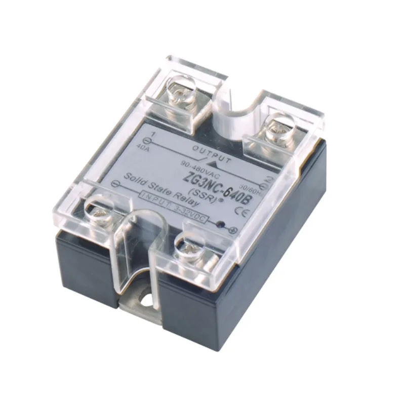
အမျိုးအစား 2: သီးခြား Heat Sinks ပါသော SSR များ
- Load current: 90A အထိ
- လျှောက်လွှာ အိမ်ရာနှင့်ကိုက်ညီရန် heat sink ကို သင်ရွေးချယ်သည့် စက်ပစ္စည်းများတွင် တပ်ဆင်ထားသည်။
- ဥပမာ: OMRON G3NA, G3NE series
- အားသာချက်- thermal management ဒီဇိုင်းတွင် လိုက်လျောညီထွေရှိမှု
အမျိုးအစား 3: Plug-In Style (စက်မှုရီလေးများနှင့် ပုံစံတူ)
- Load current: 5-10A
- လျှောက်လွှာ စက်မှုရီလေးများ၊ PLC I/O applications များအတွက် drop-in အစားထိုး
- ဥပမာ: OMRON G3F, G3H, G3R-I/O, G3RZ series
- အားသာချက်- လွယ်ကူသော retrofits များအတွက် စက်မှုရီလေးများနှင့် တူညီသော sockets များကို သုံးနိုင်သည်။
အမျိုးအစား 4: PCB-Mounted SSR များ
- Load current: 5A အထိ
- လျှောက်လွှာ Signal switching, board-level control, MOS FET relays များပါဝင်သည်။
- ဥပမာ: OMRON G3MC, G3M, G3S, G3DZ series
- အားသာချက်- တိုက်ရိုက် PCB ပေါင်းစည်းမှုအတွက် သေးငယ်သော footprint
-အစွန်အဖျား: 5A အထက် load များအတွက်၊ သင်သည် heat sinking ကို အမြဲလိုလို ထည့်သွင်းစဉ်းစားရန် လိုအပ်ပါသည်။ 5A အောက်တွင်၊ PCB-mounted SSR များသည် နောက်ထပ် thermal management မပါဘဲ ကောင်းစွာအလုပ်လုပ်သည်။.
AC vs. DC SSR များ: အရေးကြီးသော ရွေးချယ်မှု စံနှုန်းများ
ဤနေရာတွင် အင်ဂျင်နီယာများစွာသည် သတ်မှတ်ချက်အမှားများ ပြုလုပ်ကြသည်။ SSR များသည် load-specific ဖြစ်သည်:
AC Output SSR များ (အများဆုံး အသုံးပြုသည်)
- Output element: Triac သို့မဟုတ် သိုင်ရစ်စတာ မော်ဂျူး
- Load အမျိုးအစားများ: Heaters, AC motors, transformers, solenoids, lamps
- Zero-cross function: ရနိုင်သည်—EMI ကို အနည်းဆုံးဖြစ်အောင် 0V အနီးတွင် ON
- ဗို့အား အဆင့်သတ်မှတ်ချက်များ: 24-480 VAC
အရေးကြီးသော ကန့်သတ်ချက်: DC load များအတွက် အသုံးမပြုနိုင်ပါ။ triac/thyristor သည် OFF သို့ပြောင်းရန် AC waveform သည် သုညဗို့အားကို ဖြတ်ကျော်ရန် လိုအပ်သည်။ DC ဖြင့်၊ ၎င်းသည် latched ON တွင် ရှိနေသည်။.
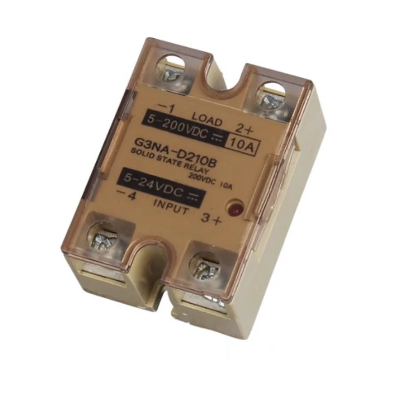
DC Output SSR များ
- Output element: Power transistor သို့မဟုတ် MOS FET
- Load အမျိုးအစားများ: DC motors, DC solenoids, DC valves, LED arrays
- ဗို့အား အဆင့်သတ်မှတ်ချက်များ: 5-200 VDC
- အားသာချက်- မြန်ဆန်သော switching (microseconds), zero-cross delay မရှိပါ။
AC/DC Universal SSR များ (MOS FET Relays)
- Output element: MOS FET နှစ်ခုကို ဆက်တိုက်ထားသည် (bidirectional current ကို ခွင့်ပြုသည်)
- Load အမျိုးအစားများ: AC သို့မဟုတ် DC—နှစ်ခုလုံးကို ကိုင်တွယ်သည်။
- အဓိကအင်္ဂါရပ်: Ultra-low leakage current (10μA vs. 1-5mA for standard SSRs)
- လျှောက်လွှာ Alarm outputs where load type is unknown, or where bleeder resistors can’t be used
သော့ယူသွားခြင်း- You must match SSR output type to your load. Using an AC SSR on DC loads will cause the SSR to latch ON permanently—it cannot turn OFF without the zero-crossing that only AC provides.
The Zero-Cross Function: Why It Matters
This is one of the most important SSR features, yet often misunderstood:
Without zero-cross function: When the SSR turns ON at a random point in the AC waveform (say, at peak voltage of 311V for 220VAC), the instantaneous current jump creates:
- Radiated electromagnetic noise
- Conducted noise on power lines
- Voltage transients from sudden di/dt (rate of current change)
- Increased stress on the load
သုညဖြတ်ကျော် လုပ်ဆောင်ချက်ဖြင့်- The SSR waits to turn ON until AC voltage is within ±10V of zero-crossing. This means:
- Current rises gradually from zero
- Minimal EMI generation
- Reduced electrical stress on switching elements and load
- Extended life for resistive heating elements and incandescent lamps
When NOT to use zero-cross:
- Phase control applications (requires random turn-on capability)
- Fast response requirements where 10ms delay is unacceptable
- Testing/measurement applications requiring precise timing control
-အစွန်အဖျား: For 90% of industrial heating, motor control, and solenoid valve applications, zero-cross function is beneficial. The small turn-on delay (max 10ms at 50Hz) is negligible compared to mechanical relay operate time (5-15ms).
Heat Dissipation: The Non-Negotiable Requirement
This is the single most important concept for SSR reliability:
Every SSR generates heat according to: Heat (W) = Voltage Drop (V) × Current (A)
For example, a typical SSR carrying 15A with 1.5V drop generates: 1.5V × 15A = 22.5 watts of continuous heat.
This heat must be removed or the semiconductor junction temperature will exceed its rating (~125°C for most devices), causing:
- Thermal runaway and destruction
- အိုမင်းရင့်ရော်မှုကို မြန်စေတယ်။
- Short-circuit failure mode
The three heat management essentials:
- Select proper heat sink based on thermal resistance (°C/W rating)
- Apply thermal grease between SSR and heat sink (never skip this)
- Ensure adequate airflow in the control panel
For loads above 10A, heat sinking is mandatory. For loads above 30A, you’ll need large aluminum heat sinks plus forced air cooling.
The Bottom Line: When SSRs Make Engineering Sense
After understanding what solid-state relays actually are, here’s your decision framework:
Choose SSRs when you need:
- High-frequency switching (>100k total operations over product life)
- Noise-free operation in sensitive electronic environments
- Long maintenance-free operation in remote or difficult-to-access locations
- High-speed response (<5ms)
- Immunity to shock, vibration, and harsh atmospheres
- No audible click or mechanical wear
Choose mechanical relays when:
- You need multi-pole switching in compact space
- High current switching (>30A) with minimal heat generation
- Initial cost is the primary driver
- Voltage drop across the switch must be minimal (<0.2V)
- Low-frequency switching makes contact life acceptable
The hybrid approach: Many systems use mechanical contactors for main power switching and SSRs for high-frequency control signals—combining the strengths of both technologies.
Understanding what a solid-state relay fundamentally is—a semiconductor-based switch with optical isolation and no moving parts—gives you the foundation to make informed design decisions. The premium cost is justified when switching frequency, maintenance requirements, or environmental conditions make mechanical relay life unacceptable.
The key is matching the technology to your application requirements, not defaulting to what you’ve always used before.
